CHAPTER 6
![]()
Tools for Quality Electrical Work
The quality of your electrical installations will depend on your knowledge and expertise plus the degree of manual dexterity you have. Still another very significant part of the picture is the variety and quality of the tools that you bring to the job. To do successful electrical installations, the home crafter-electrician, no less than the full-time professional, must be well equipped. The tools that you will need fall into two broad categories—test equipment and installation tools.
Test Equipment
We’ll start with some inexpensive and modest items and progress toward the top of the line. The first and most basic need is to test for the presence or absence of voltage without regard to the exact level, where level is not an issue. You need an instrument that will do this to verify that wires and terminals are not live prior to working on them. The same tool is used when diagnosing and repairing equipment and circuits to determine whether they are energized. It is to be emphasized that the instrument should be tested immediately before each use to ensure that you are not deceived by a dead battery, open probes, or a burn-out indicator light or meter.
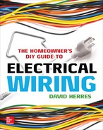
A very basic tool you can make at low cost is a plug-in lamp socket equipped with an appliance bulb. (These bulbs, because of the tight radius of the glass envelope, do not break easily, and the short filaments will withstand a lot of vibration and rough handling.) This test light, shown in Figure 6-1, can be quickly plugged into any receptacle and left in place to indicate the status of the circuit while you work on it. For testing receptacles, it is superior to the best meter money can buy because with meter probes in a receptacle, you never know for sure when you are getting a good contact.
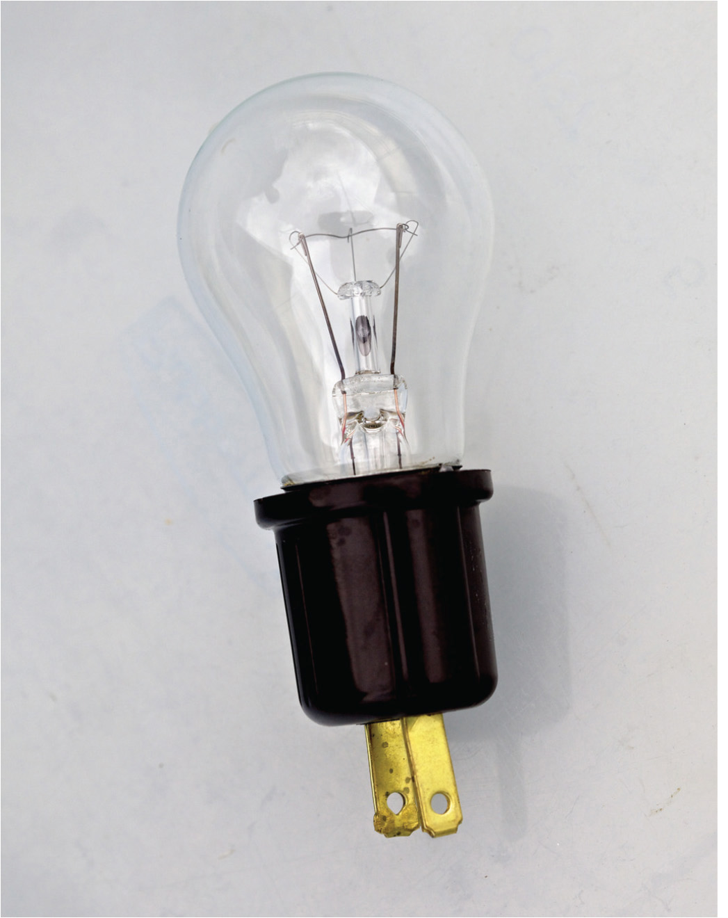
FIGURE 6-1 Plug-in lamp socket.
A variation on this type of indicator is an appliance bulb screwed into a lamp socket that is equipped with wire leads, as shown in Figure 6-2. Such a socket can be bought from your electrical supplier or saved from a light fixture that is being discarded. (It is good to have a dozen or so of these sockets with leads on hand because they are also used as temporary lighting after the branch circuits are roughed in but before the finish ceiling and wall materials have been installed.)
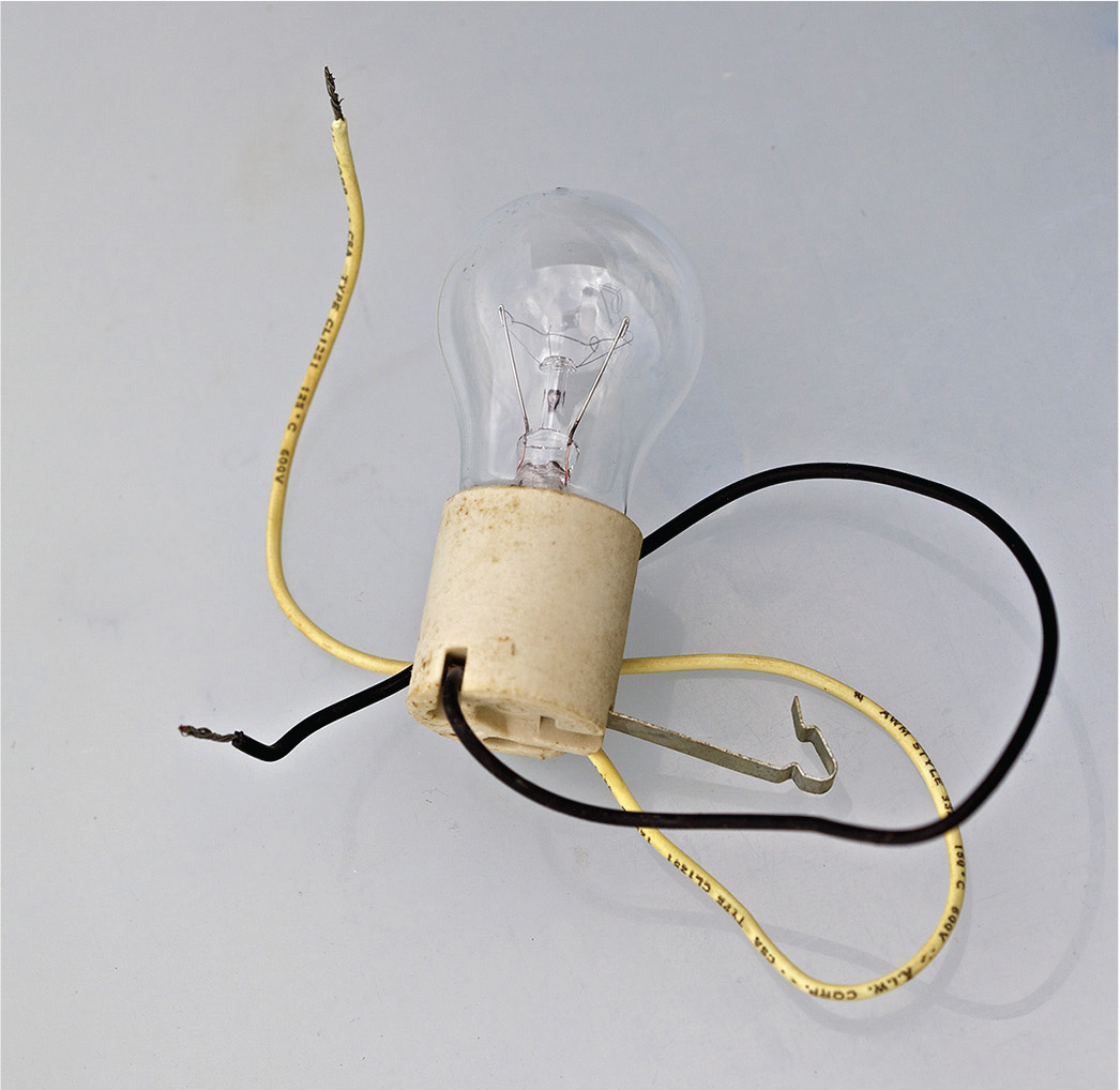
FIGURE 6-2 Lamp socket with leads.
Moving up the cost scale, the next test instrument is the neon test light shown in Figure 6-3. It is quick and convenient for checking for presence or absence of voltage, and it rarely breaks or fails electrically. The bulb and probes are very durable, and the initial cost is modest. Still, verify operation prior to each use if there is any possibility that you will make contact with live terminals or conductors. The rule is to check first, and then, even when the equipment is known to be dead, use insulated tools and avoid touching conductors and terminals.
FIGURE 6-3 Neon test light.
The neon test light will discriminate between 120 and 240 volts. You can rapidly move all over an entrance panel or load center, checking phase-to-phase and phase-to-ground voltages at main and branch-circuit breaker terminals. This little tester is excellent for working inside a tool or appliance and for checking for voltage at motor terminals. You also can slide a probe inside a wire nut without disrupting the connection.
Another tool that is favored by many experienced electricians is the solenoid voltage tester (trade name Wiggie), as shown in Figure 6-4. This compact instrument has flexible leads so that the probes are capable of getting into tight places. Multiple neon bulbs indicate voltage levels, so this instrument provides more detailed information than the simple neon light.
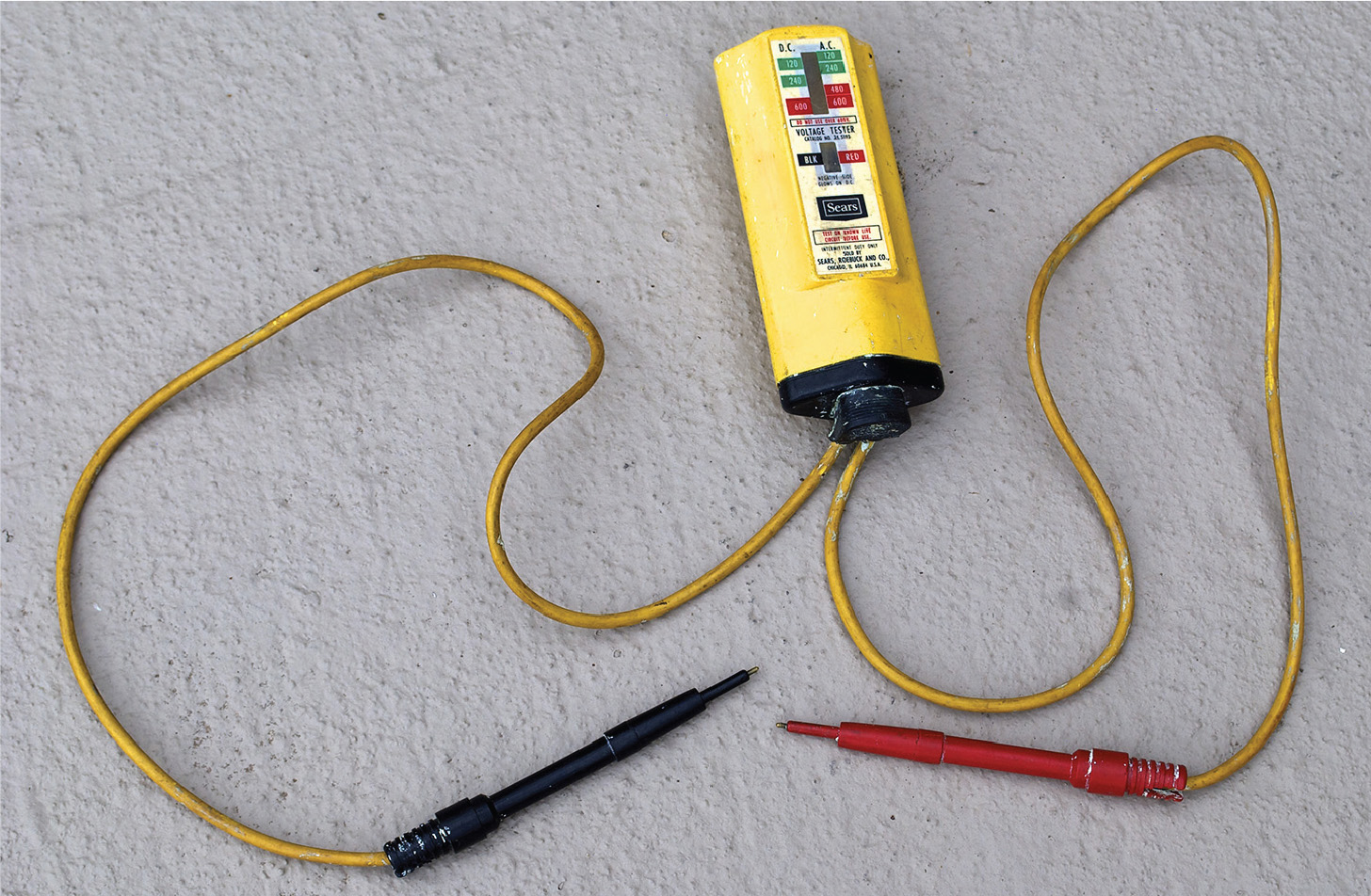
FIGURE 6-4 A solenoid voltage tester.
You may have noticed that it is sometimes difficult to get a good reading with a conventional mutimeter because it is necessary to hold the probes so that they contact the terminals and to simultaneously watch the readout. The solenoid voltage meter addresses this difficulty with great competence. At the top of the case are brackets that will hold one or both probes. With a probe mounted to the case, you can use one hand to position the other probe and, at the same time, hold the meter and view the readout. Moreover, when the probes contact metal surfaces that are at different voltage levels and when they break contact, the instrument emits a very loud click. As long as the probes are connected to an alternating-current (ac) circuit, there is a loud buzzing sound. This can be felt when you are holding the housing as a very distinct vibration, which is helpful in noisy surroundings.
The solenoid tester is line powered, so it does not depend on a battery, although some models require a battery for an auxiliary ohmmeter function. The instrument is a low-impedance voltmeter, so it should not be used for sensitive electronics work, where it would load the circuit. It is at its best for power and light circuits in ordinary house wiring. Because of the low impedance, it should not be continuously connected to a live circuit for any length of time because it would overheat and burn out.
A side benefit is that the solenoid voltmeter can be used to test a ground-fault circuit interrupter (GFCI). Connect the probes to the hot line and equipment ground at the GFCI output or anywhere down the GFCI-protected line. The solenoid voltage tester draws enough current so that the GFCI will think that there is a ground fault and will trip out.
The electrician’s next test instrument moving up in complexity and functionality is the multimeter, variously called a volt-ohm milliammeter (VOM) and a digital volt milliammeter (DVM). The multimeter is available in two versions, analog and digital. The old analog type is still manufactured and sold, and some old-time electricians prefer it. It has a needle that sweeps across a face on which are printed separate scales for different functions and ranges. A built-in reflective zone is helpful in ensuring that the needle and scale are being viewed straight on. The analog meter, shown in Figure 6-5, is more reliable in very cold surroundings.

FIGURE 6-5 Analog multimeter.
Today, most electricians favor the digital multimeter. An alphanumeric readout displays the circuit parameter of interest. The multimeter is easy to read and interpret.
Digital multimeters are available in inexpensive versions for under $10, as shown in Figure 6-6, and this is a good way to get started. Better digital multimeters have more extensive ranges, are easier to read, and, with rugged rubberized cases, withstand dropping and rough handling. You’ll pay over $100 for an excellent model with capacitor and diode check functions.

FIGURE 6-6 An inexpensive digital multimeter adequate for most electrical work.
The voltage function is useful for checking for the presence or absence of voltage and will measure the exact level accurately and reliably. Although voltage measurements are made with the circuit powered up, the ohmmeter function is used only when the circuit is not live and any stored voltage (due to electrolytic capacitors or distributed capacitance) is bled out of the equipment. If there is a chance of a parallel current path, the circuit or device being tested has to be taken out of its larger electrical environment. To do this, it is necessary to open just one, not both, of the connections.
Most multimeters in the ohms function have a continuity indicator, which is an audio tone that sounds when the meter reads less than (typically) 30 ohms. It is very helpful for quickly testing circuits, equipment, and devices such as fuses and switches on a go, no-go basis.
Electric current in a circuit also can be measured, and this is done, of course, when the unit is powered up. There are two drawbacks to using a multimeter for this purpose. One is that to take an ampere measurement, it is necessary for the entire current to pass through the meter. Therefore, the circuit must be cut open so that the meter can be put in series with the load. The other disadvantage in using a multimeter for amperage measurements is that the meter is only able to deal with a low level of current. The amount of current drawn by a typical household load, even a low-wattage light bulb, would be outside the highest range of a multimeter in amperes mode and would instantly overheat and destroy the meter.
The multimeter is nevertheless the single most useful test instrument in an electrician’s tool box, and the home crafter-electrician definitely must have one, even if it is an old yard sale analog meter or the low-end model purchased at a “big box” store. If you can justify a really good meter, that is the way to go. Doing electrical work, you’ll use it at least once a day, and it will last many years.
Another piece of test equipment that professionals value highly is the clamp-on ammeter (trade name Amprobe), as shown in Figure 6-7. The home crafter-electrician will not need one of these instruments in the course of ordinary electrical installations in the home, but in a typical appliance repair shop, it may be the only way to get the information you need to proceed.
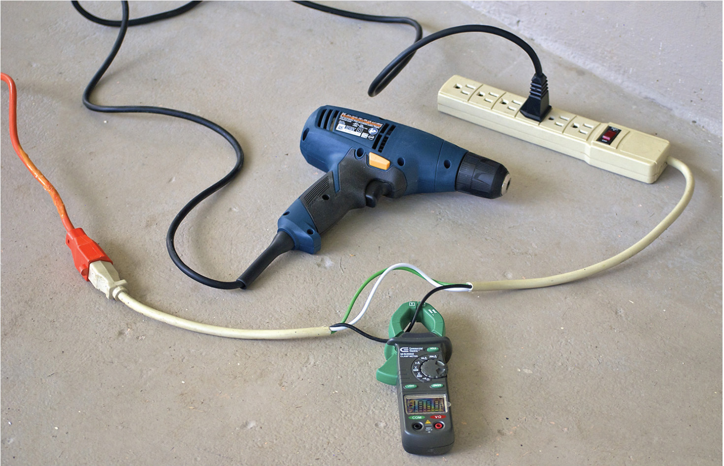
FIGURE 6-7 Clamp-on ammeter measuring current drawn by a portable power tool. Notice the homemade splitter, permitting reading a single conductor.
The clamp-on ammeter may be analog or digital. The old analog tester is line powered and has no battery. These vintage models work fine. The digital clamp-on ammeter, with an auxiliary ohms function, requires a battery and incorporates additional features such as a hold button that enables the readout to retain the highest reading.
To measure current, you open the jaws and clamp them around a live (insulated!) conductor. The clamp-on ammeter is not placed in series with the load. Instead, it measures the magnetic field that surrounds any conductor through which current is passing. The instrument is capable of reading up to 200 amperes and has no measurable effect on the circuit being tested. It does not matter if the conductor is precisely centered in the jaws, nor does it matter if the conductor passes through at an angle.
The current drawn by a cord-and-plug–connected tool or appliance cannot be measured by clamping around the power cord. Because current in hot and neutral conductors is traveling in opposite directions, the induced magnetic fields cancel out, and a zero reading results. To measure current in a power cord, go inside the equipment, junction box, or entrance panel, where, with no simultaneous load online, it is possible to clamp around a single conductor, hot or neutral, to obtain a reading.
The circuit analyzer is an inexpensive test instrument that every electrician, professional or otherwise, should have. Plug it into a receptacle, and it will indicate any reversed or missing circuit elements. It is a quick and easy test for the presence or absence of voltage.
These are the basic electrical test instruments. For the home crafter-electrician, the entire array is not necessary. The instruments can be obtained on an as-needed basis. A viable plan would be to start with a neon test light, low-end multimeter, and circuit analyzer and take it from there.
Electrical Installation Tools
As for installation tools, you will need the usual carpentry tools, such as a hammer, tape measure, plumb bob, level, hand saw, portable circular saw, electric drill with a good selection of bits, rubber mallet, and so on. You will also need the usual mechanic’s tools, such as open-end and box wrenches; socket wrenches with ¼-, ⅜-, and ½-inch drives; adjustable wrenches; Vise-Grips; water-pump pliers (small, medium, and large); and slip-joint pliers.
There are many electrician’s tools, some essential and others more expensive and in the optional category. Here’s a rundown, beginning with some tools you can’t be without.
You can make do with an automotive-type wire stripper, but the specialized electrician’s wire stripper, shown in Figure 6-8, works much better. It is smaller, able to get into tight places, and incorporates a high-leverage, sharp wire cutter. If you value the way it snips easily through large copper conductors, you will refrain from using it on steel wire. The stripping cutters close down on the insulation without nicking the copper. There are different sizes marked for stripping solid versus stranded wire. The only disadvantage with this otherwise convenient little tool is that you have to look carefully to find the right cutter every time you want to strip a wire. The solution is to enamel small, different-color dots for stranded and solid 12 American Wire Gauge (AWG) wire. Then they, along with the neighboring 10 and 14 AWG strippers, will be easy to find.

FIGURE 6-8 Professional electrician’s wire stripper.
The electrician’s wire stripper also incorporates a gripper with knurled jaws that is useful for pulling wires out of tight places and myriad other tasks. The drilled holes are intended for determining conductor gauges, but they are useful also for forming wire ends so that they can be terminated.
Needle-nose pliers, shown in Figure 6-9, are absolutely essential for wiring switches and receptacles, as well as for many other tasks around the work site. You want a medium-sized pliers—not too large and not too small. The idea is that the diameter of one of the grippers should be equal to the diameter of the wire coil that will easily fit under a switch or receptacle screw terminal. If you form these wire ends properly, your terminations will be quick and easy with high-quality results. Grab the stripped end with your needle-nose pliers, and roll it in the proper direction (clockwise) so that when the terminal screw is tightened, the coil will wind tighter, not loosen. While coiling the wire end, form it at a slight angle so that when you insert it under the screw, the leading end will lean in toward the device. This makes it easier to get the wire under the screw. The NEC states that such a coil is to form at least three-quarters of a circle around the screw. You can do better than that. Before tightening the screw, use your needle-nose pliers to squeeze the wire more tightly around the screw. Then tighten the screw very firmly, and you will have an excellent low-impedance connection that will last forever. Do this on each and every termination that you make.
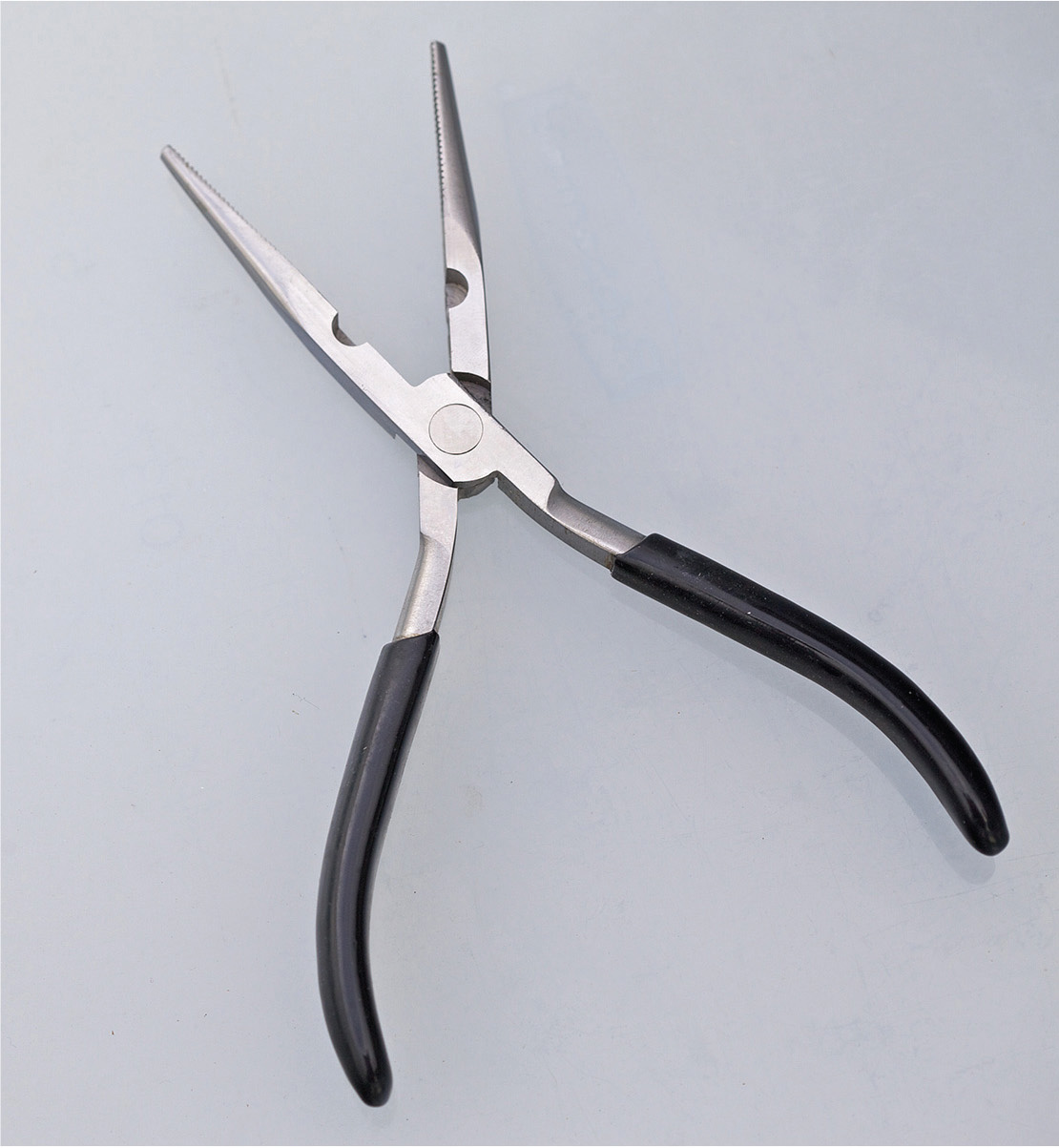
FIGURE 6-9 Needle-nose pliers.
As for screwdrivers, the very inexpensive six-way screwdriver with two Phillips sizes, two straight-blade sizes, and two nut drivers is very convenient for lots of work. The thick handle permits application of torque where needed. This tool will be adequate most of the time, but there are some specialized screwdrivers that are indispensible now and then.
The so-called electrician’s screwdriver, shown in Figure 6-10, is a great help for certain difficult tasks. It has a very long, thin shank with a small, straight blade, and it is perfect for getting into tight places. With the thin shank, you can spin it rapidly between your fingers, making short work of a long haul.
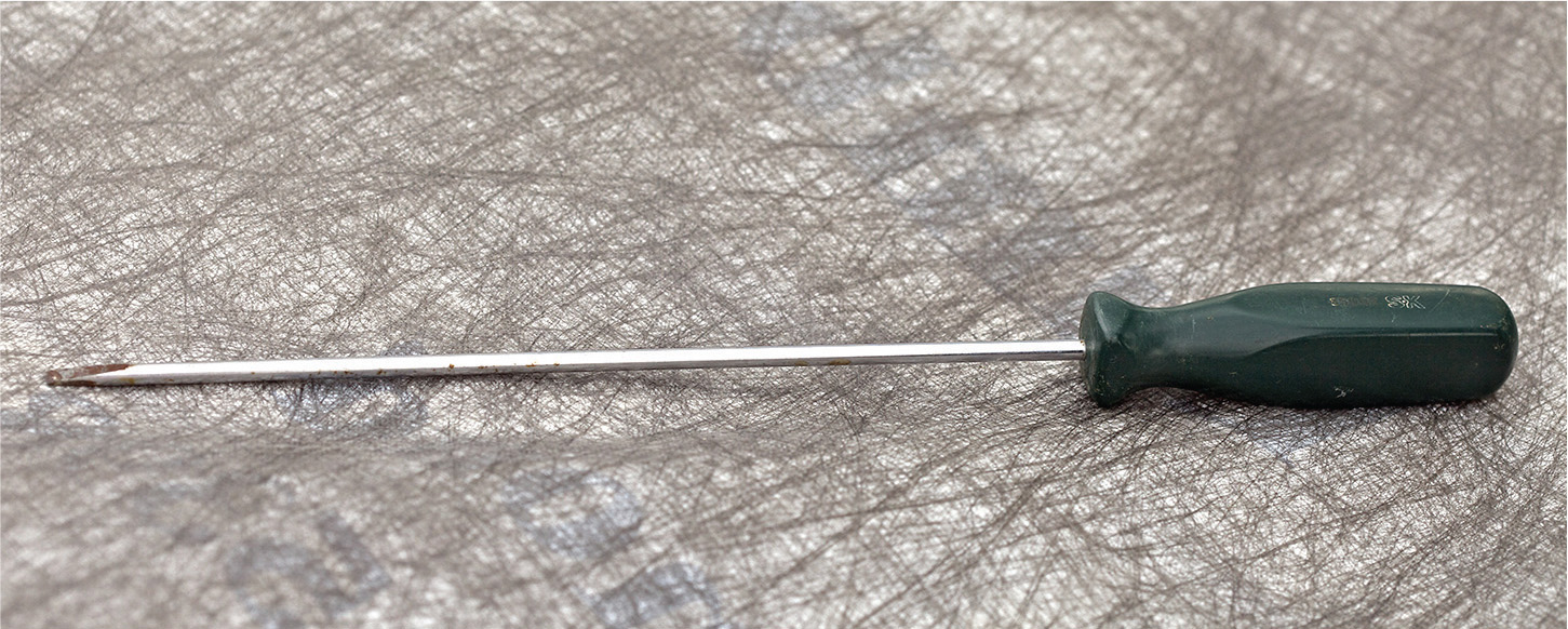
FIGURE 6-10 Electrician’s screwdriver.
In close quarters, a standard screwdriver may be too long and possibly won’t fit. You need to have on hand Phillips and straight-blade stubby screwdrivers, shown in Figure 6-11, in at least two different sizes. Sometimes a screw has to be started in a very tight, difficult place where you can’t get your hand in position to start it and you can’t maneuver it into position with a screwdriver with a magnetized bit. For this, you need a screw-starter type of screwdriver. You should have two or three different sizes. The best place to buy this type of tool may be a local auto parts store.

FIGURE 6-11 Stubby screwdriver.
A necessity in the electrician’s toolbox is a large diagonal cutter (dike), shown in Figure 6-12. It’s perfect for cutting Romex, reaming electrical metallic tubing (EMT), and many other tasks every day. Another good tool is a large pair of lineman’s pliers. These are also used every day.

FIGURE 6-12 Large diagonal cutter.
A cordless drill, shown in Figure 6-13, is a very basic tool that is used very frequently in electrical work. Besides drill bits, you will want Phillips bits for driving the ubiquitous drywall screws that are so much a part of our lives these days.

FIGURE 6-13 It is hard to imagine doing much electrical work without a cordless drill.
There are some more advanced electrician’s tools that are good to have, but they are not essential for residential work. Many of them have to do with metal conduit installation. This is permitted in dwellings but is rarely seen because Romex is much less expensive and easier to install. In dwellings, raceways may be used in the service and for some electrical equipment. Polyvinyl chloride (PVC) works for most of these applications, so elaborate tooling is not needed.
Conduit benders, knockout punches, hole saws, and similar items can be purchased as needed, so it is not necessary to invest heavily in these types of specialized tools.