![]()
Glossary
Ampacity The amount of current, measured in amperes, that a conductor can carry without damage, usually to the insulation. The ampacity depends on the size of the wire, the type of insulation, the ambient temperature, the duty cycle, the duration, and other factors.
Ampere A measure of current flowing through a conductor, source, or load. The amount of current is one ampere when 6.25 × 10¹⁸ electrons per second pass a given point in the circuit.
Branch circuit The conductors between the final overcurrent device protecting the circuit and the outlet.
Cable Conductors usually contained within an outer jacket, as shown in Figure G-1. Additionally, a single conductor that is 6 American Wire Gauge (AWG) and larger without an outer jacket is referred to as cable. A specialized conductor assembly such as submersible-pump cable has no outer jacket.

FIGURE G-1 Various types of cables, raceways, and conductors.
Capacitance Typically provided by parallel conductive plates separated by a dielectric layer, it is characterized by an ability to store electric charge. It has less impedance to high-frequency electric current and maximum impedance to direct current.
Circuit breaker An overcurrent device that may be reset and reused, as shown in Figure G-2, as opposed to a fuse, which is destroyed by overcurrent.
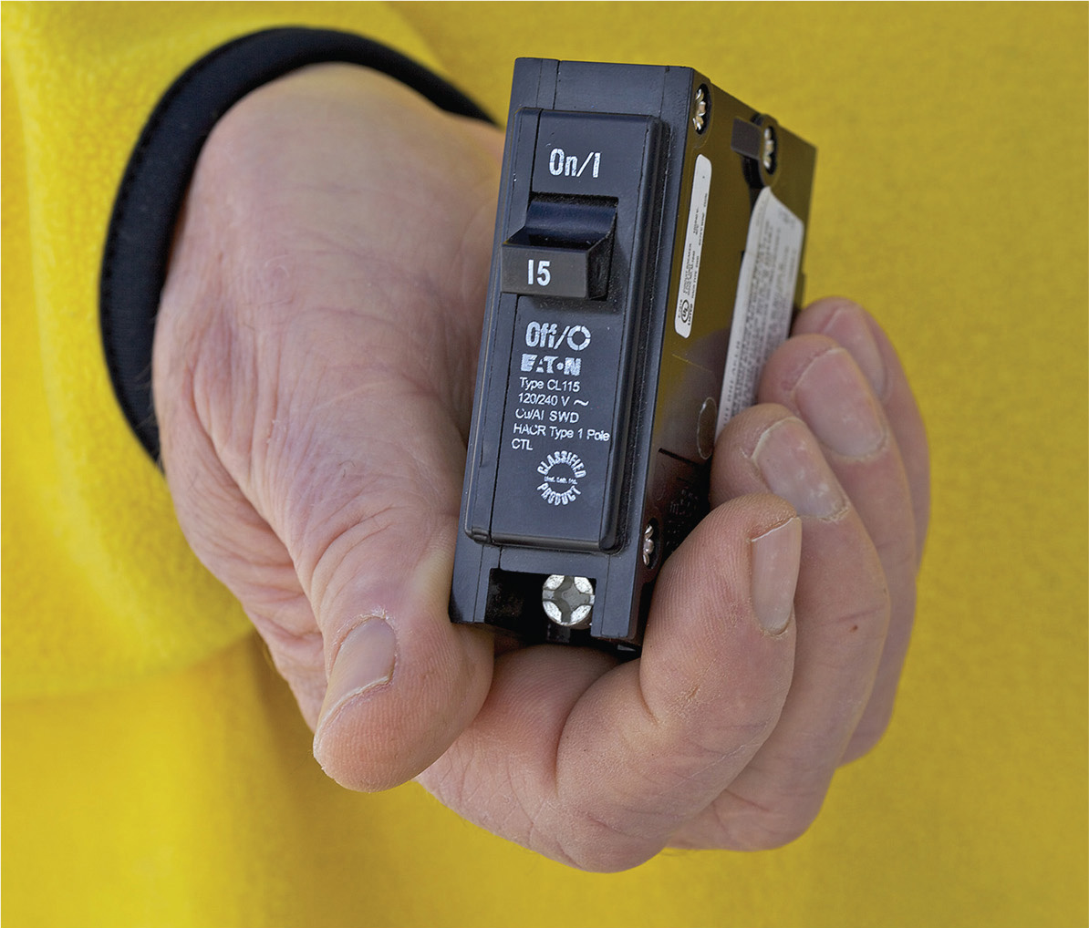
FIGURE G-2 A single-pole circuit breaker, widely used in residential entrance panels.
Coil Also called an inductor, as shown in Figure G-3, a coil is formed when a conductor is wound around a core such as air or soft iron, producing a magnetic field when current flows through it. The coil then exhibits inductance, having greater impedance to higher frequencies and zero impedance (except for incidental resistance) to direct current.

FIGURE G-3 Schematic diagram symbol for a coil.
Conductor A material, shown in Figure G-4, usually metal drawn out in the form of a wire, that forms a path for electric current to travel.

FIGURE G-4 Conductors are available in many colors, aiding in identification.
Conduit body A fitting in a raceway system, shown in Figure G-5, designed to provide access through a removable cover to the interior of a system to facilitate pulling conductors.
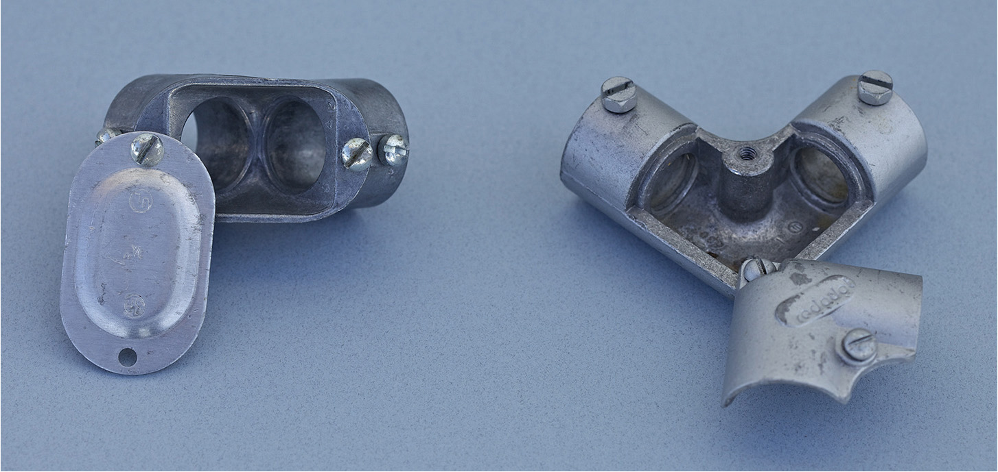
FIGURE G-5 The removable cover facilitates pulling of conductors.
Continuous duty A load that is expected to be connected to the power source for three or more hours.
Current The flow of electrons through a conductor, power source, or load. In a series circuit, where there are no parallel paths, it is the same at every point.
Demand factor The ratio of the maximum demand of a system to the total connected load.
Device A unit of an electrical system, shown in Figure G-6, that carries or controls electrical energy as its principal function. It does not consume power except incidentally due to a small amount of resistance.
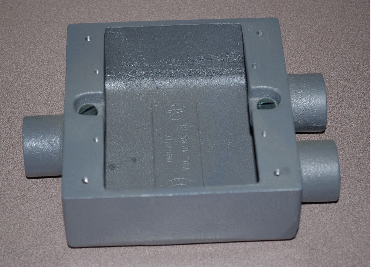
FIGURE G-6 Devices are available in a great many types and sizes for different purposes.
Diode A semiconductor device with two terminals, shown in Figure G-7, allowing the flow of current in one direction only. It is forward biased when positive voltage is present at the anode and reverse biased when positive voltage is present at the cathode. Accordingly, it can be used to change alternating current to pulsating direct current, which can be subsequently filtered to make pure direct current, a process known as rectification.

FIGURE G-7 Schematic diagram symbol for a diode.
Equipment-grounding conductor A bare or green wire or other conductive material, usually run in cable or raceway with the circuit conductors, that is capable of returning fault current to the electrical system grounded neutral, facilitating operation of the overcurrent device.
Feeder All circuit conductors between the service equipment or other power-supply source and the final branch circuit overcurrent device. A feeder always has overcurrent devices at both ends.
Fitting A locknut, bushing, or other accessory to a wiring system, shown in Figure G-8, that performs a mechanical rather than an electrical function.
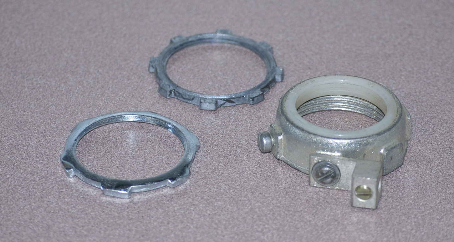
FIGURE G-8 A great many fittings are needed to make a premises, electrical system work.
Grounding electrode A device placed in the ground for the purpose of providing a grounding connection to the Earth, shown in Figure G-9. Examples are the familiar ground rod, ground plate, ground ring, and Ufer grounding system inside poured concrete.

FIGURE G-9 Water pipe as a grounding electrode.
Grounding-electrode conductor A wire that connects the grounded neutral, usually inside the meter socket enclosure, to the grounding electrode.
Inductance The property of an electrical device or circuit by which an electromotive force is induced in it as the result of a changing magnetic flux. Inductance may be intentional, as provided by an inductor, or unintentional, for example, parasitic inductance in a transmission line.
Insulation A material, shown in Figure G-10, that restricts the flow of electric current. Electrical conductors are provided with a covering of insulation to protect humans from shock and to prevent fault current from flowing to ground or to other conductors that are at a different voltage potential. The amount and type of insulation must be appropriate to the voltage applied to the conductor and to the maximum anticipated temperature.

FIGURE G-10 Insulation is required for most conductors.
Intersystem bonding termination A device, shown in Figure G-11, that provides a means for connecting bonding conductors for communications and other systems to the grounding-electrode system.
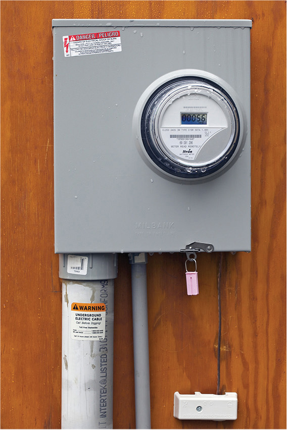
FIGURE G-11 The intersystem bonding termination, in the small white plastic enclosure below the meter socket, is a required part of every new service.
Main bonding jumper A screw, busbar, wire, or other conductor that provides the connection in a service enclosure between the neutral bar and the grounding terminal or metal cabinet and subsequently to all equipment-grounding conductors. The main bonding jumper is field installed because it is not to be used where this connection has been made in another upstream enclosure.
Main disconnect A switch, often taking the form of a circuit breaker, shown in Figure G-12, that is capable of disconnecting premises wiring from the electrical supply. It is located in the entrance panel or within a separate upstream enclosure, indoors or out.
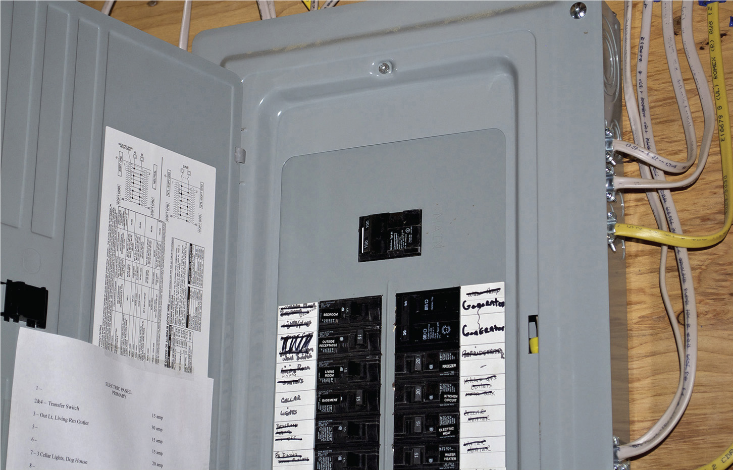
FIGURE G-12 The main disconnect is frequently located in the service-entrance panel.
Molded-case switch A switch that may be installed in an electrical enclosure. It resembles a circuit breaker but does not provide overcurrent protection.
Neutral bar A conductive strip provided within an entrance panel or load center, with terminals for the connection of grounded conductors that are part of branch circuits.
Neutral conductor A grounded conductor, color-coded white, shown in Figure G-13, that is connected to the neutral bar in an entrance panel or load center. It provides the return path for current from the connected load.
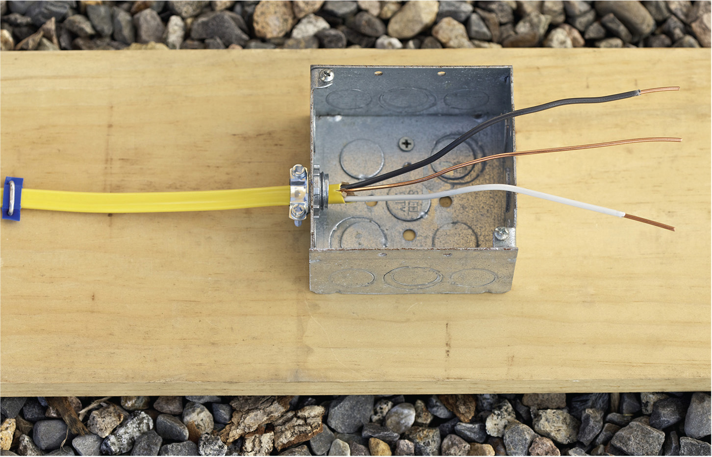
FIGURE G-13 The grounded conductor is in most systems the neutral conductor. It is white and is not to be confused with the bare or green equipment-grounding conductor, which is at the same potential but serves a different purpose.
Overcurrent device A device capable of providing protection for service, feeder, branch circuits, and equipment over the full range of overcurrents between its rated current and its interrupting rating. Fuses, shown in Figure G-14, and circuit breakers are examples.
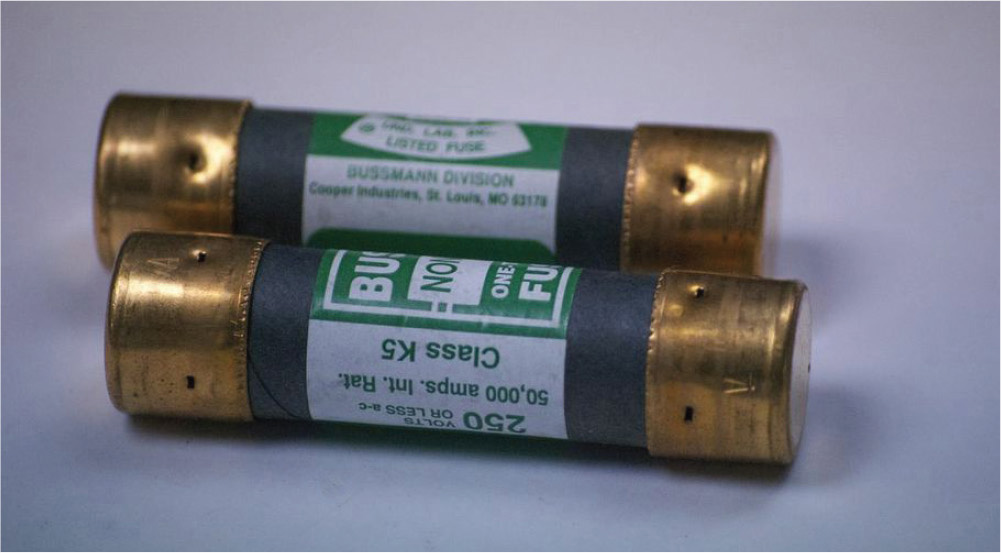
FIGURE G-14 Cartridge fuses are reliable overcurrent devices.
Power Electrical power is the rate of doing work, measured in watts, and represented by the letter P. It is transferred from the source to the load. Watts is the product of amperes and volts.
Raceway An enclosed metallic or nonmetallic channel designed to hold wires, cables, or bus bars. Conduit is one type of raceway. Type EMT is not conduit. It is tubing. Fittings are shown in Figure G-15.

FIGURE G-15 Type EMT fittings: set-screw type at the left for indoor work and compression-type at the right for outdoor work.
Reactance The opposition of a conductor or load to a change in electric current or voltage due to inductance or capacitance. It is measured in ohms, but unlike resistance, it varies with frequency. Thus there is inductive reactance and capacitive reactance. Reactance and resistance together comprise impedance.
Receptacle A device, shown in Figure G-16, installed at an outlet for the connection of an attachment plug.
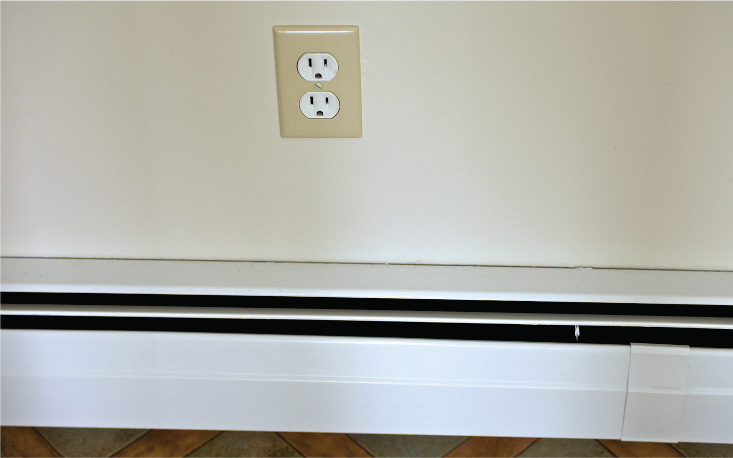
FIGURE G-16 This wall receptacle is improperly located above a baseboard heat unit.
Semiconductor A material, frequently crystalline silicon, that is formed of alternate layers of P- and N-type material. The semiconducting junctions will either conduct or not conduct a high-level current as they are variously biased by a low-level voltage. For this reason, they may be used as rectifiers, amplifiers, oscillators, and in digital switching applications. A transistor schematic is shown in Figure G-17.

FIGURE G-17 This transistor schematic shows the base, emitter, and collector with terminals attached.
Service The conductors and equipment, shown in Figure G-18, for delivering electrical energy from the serving utility to the wiring system of the premises served.

FIGURE G-18 Service drop with point of connection and weatherhead.
Service drop The overhead conductors between the utility electrical supply system and the service point.
Switch A device, shown in Figure G-19, that is capable of making or breaking an electrical circuit. It can be operated manually or automatically.

FIGURE G-19 Rocker switches combined with a ground-fault circuit interrupter (GFCI) are an attractive feature in this upscale bathroom.
Transfer switch An automatic or manual device for transferring one or more load conductor connections from one power source to another. A transfer switch suitable for residential applications is shown in Figure G-20.

FIGURE G-20 A limited number of selected circuits are chosen to be energized by the alternate power source during a utility outage.
Transformer A device, shown in Figure G-21, consisting of two or more coils wound around the same iron or air core. If an electrical supply is connected to one coil, voltage will appear at the terminals of the other(s). The amount of voltage is determined by the ratio of turns in the primary (input) winding to turns in the secondary (output) winding. Thus it is possible to make a step-up or a step-down transformer. If the number of turns is equal, the input and output voltages are the same. Such a device can serve as an isolation transformer.

FIGURE G-21 A pole-mounted transformer connected to the service for an individual home.
Transistor A device that amplifies, oscillates, switches, or otherwise modifies the voltage at two output terminals in accordance with the voltage and/or current at two input terminals. One input terminal and one output terminal are usually common, so the most basic types of transistors have three leads (Figure G-22).
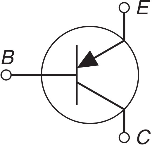
FIGURE G-22 Schematic diagram symbol for a PNP transistor.
Uninterruptible power supply (UPS) A power supply, shown in Figure G-23, used to provide alternating current to a load for some period of time in the event of a power failure. Unlike a backup power source, there is no time interval without power.
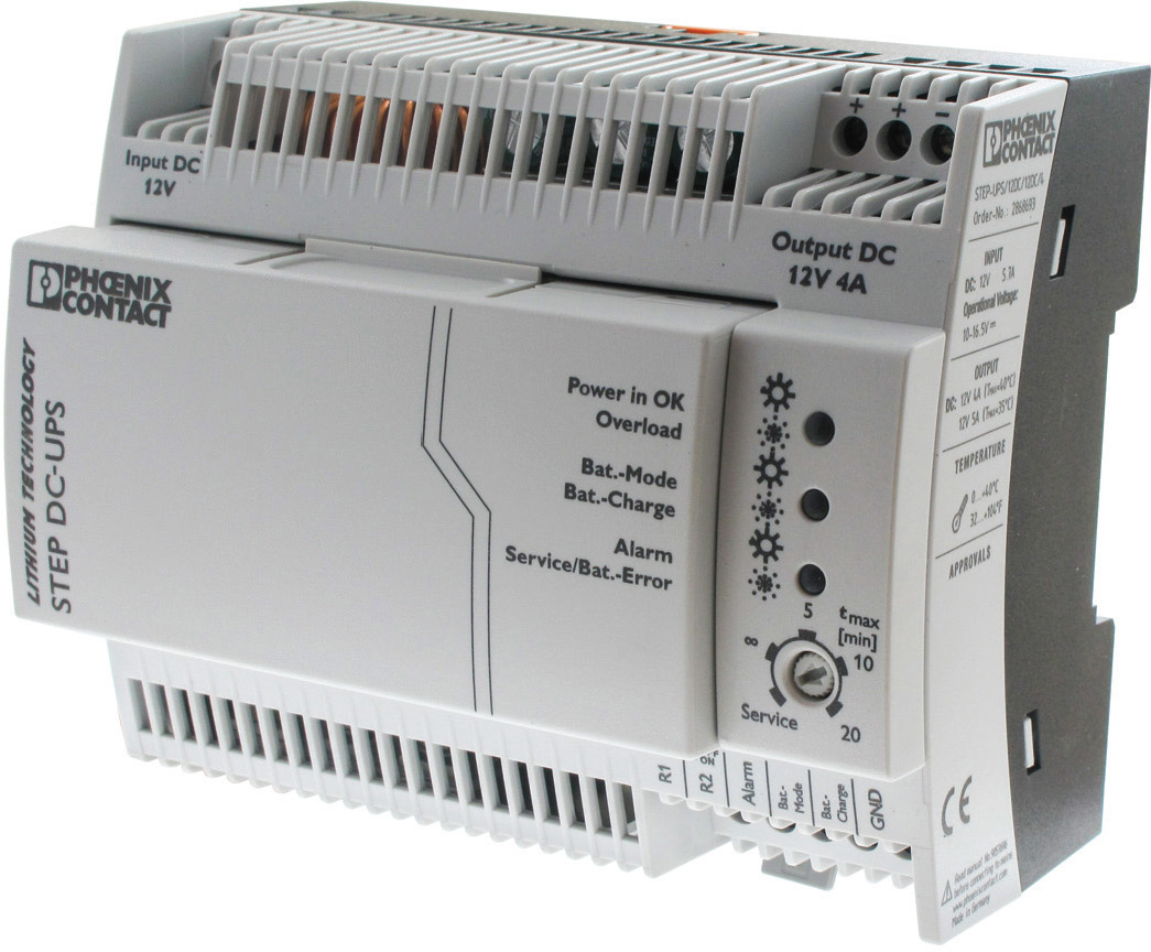
FIGURE G-23 A UPS prevents computer crashes when utility power is lost. (Courtesy of Mouser Electronics.)
Utility-interactive inverter An inverter, shown in Figure G-24, intended for use in parallel with an electric utility. The device must exactly match voltage and frequency and synchronize the waveform.
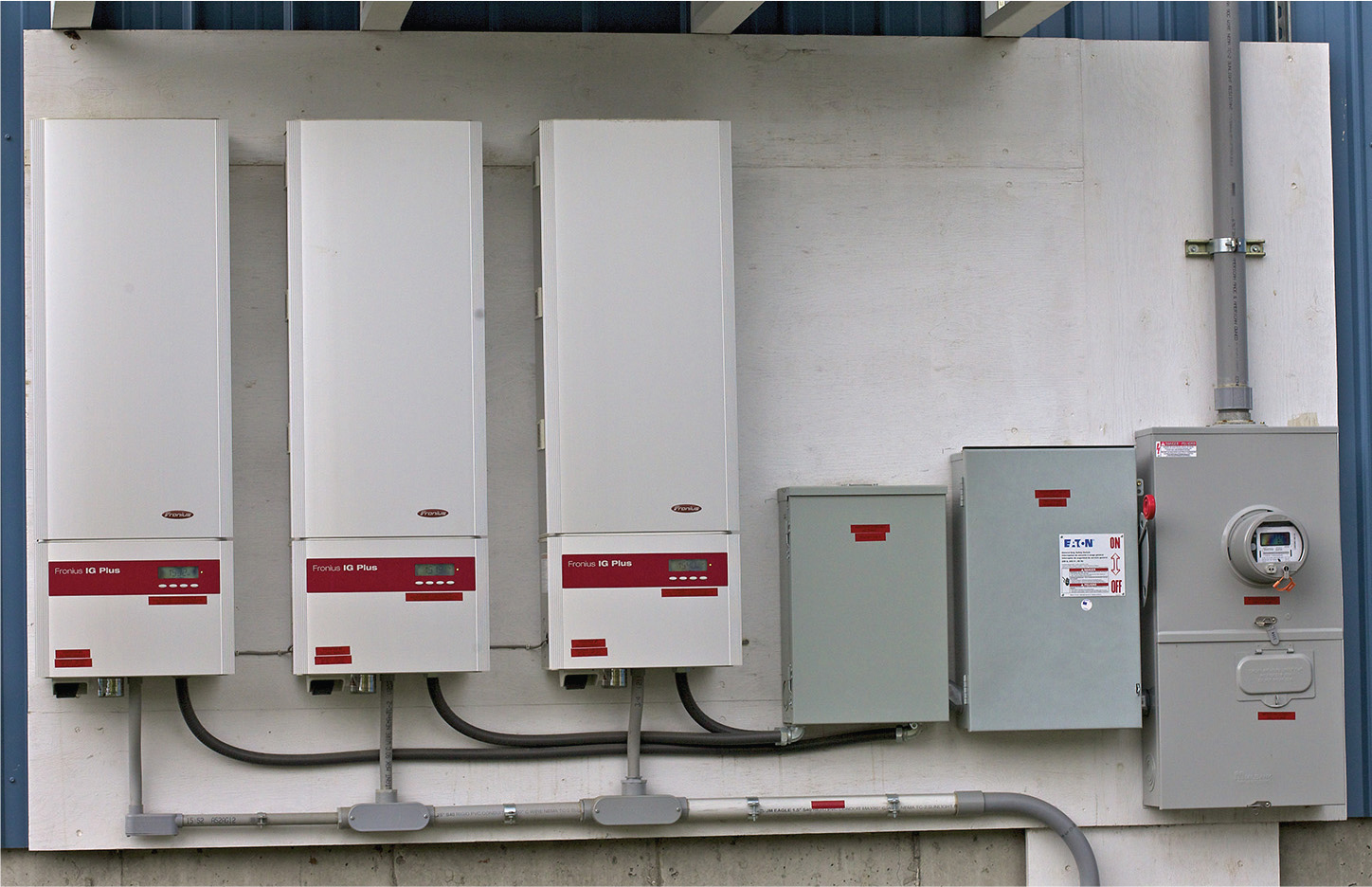
FIGURE G-24 A utility-interactive synchronous inverter. (Courtesy of Kaco.)
Volt The amount of electromagnetic force (EMF) required to force a current measuring one ampere to flow through a load having an impedance of one ohm.
Watt A measure of the amount of power transferred from a source to load. Dc amperes times volts is equal to watts.