CHAPTER 5
![]()
The National Electrical Code: Fundamental Requirements for Residential Work
Professional electricians are guided in every detail of their work by the National Electrical Code (NEC). The home crafter-electrician likewise must follow the requirements contained in this extensive document. The object is to create an electrical installation that is not a hazard to the worker(s) during construction and also will not endanger the end users. If you are doing electrical work, regardless of size and even if it is limited to your own home, it is essential to possess a copy of the NEC and to refer to it at each stage of construction.
Understanding the NEC
Because the NEC is lengthy and complex, it is sometimes a challenge to find the information you need in a timely fashion. You don’t want to be Code hopping, just flipping pages in hopes of finding an answer. You need to have a system for navigating throughout this 600-page document (Figure 5-1). The key is to understand its structure. It is useless to attempt to memorize all the Code mandates or even a fraction of them. If you could count all the bits of information including data in tables, the number would be overwhelming. So how do you proceed?
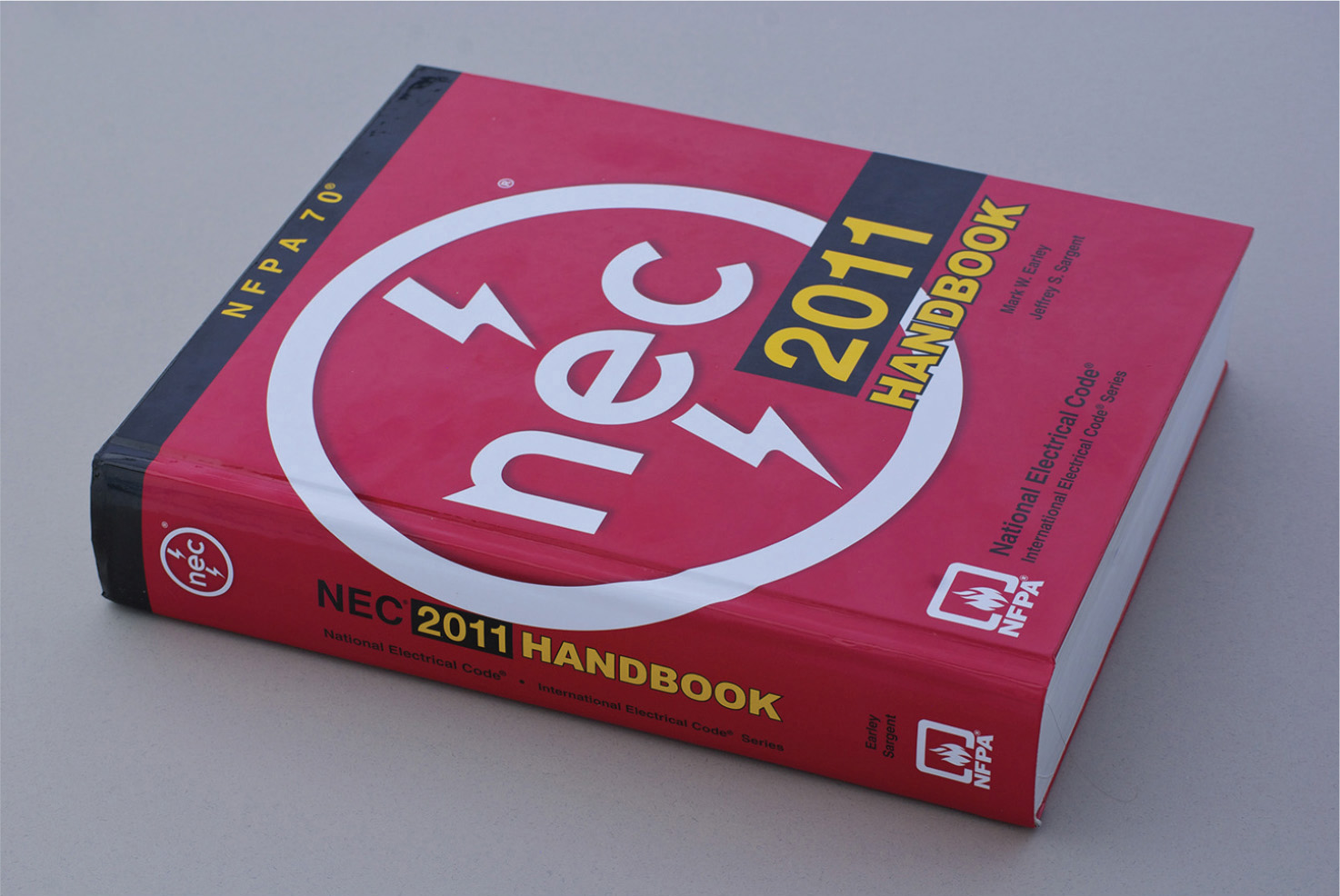
FIGURE 5-1 The NEC Handbook, containing the complete Code text plus commentaries, photographs, and diagrams.
A certain amount of memorization is needed, but it is not an impossible task. To begin, learn the titles of the nine chapters in their correct order. This will go far in helping you to visualize the overall Code structure.
The NEC is revised every three years, and the changes are invariably numerous and have a great impact on the way that work is to be done. Although some jurisdictions are slow to adopt the current NEC edition, others jump right on the wagon in a timely fashion. The timing can be clarified by contacting your local zoning board. In the discussions that follow, we’ll focus on the 2014 NEC. Except for a few isolated instances, this will work. Many changes in the 2014 NEC are not applicable to residential locations, and others are minor alterations of syntax or wording that do not have to concern us.
2014 NEC Changes
Here are the principal 2014 NEC changes that apply to residential work and are essential for the home crafter-electrician:
• Section 110.26(E)(2), “Dedicated Equipment Space. Outdoor.” The dedicated space for electrical equipment is equal to the width and depth of the equipment, and it extends from the grade to a height of 6 feet above the equipment. No piping or other equipment that is not part of the electrical installation is permitted to be located in this zone. Gas piping; water piping; refrigeration lines; and phone, cable, and satellite equipment may not occupy the dedicated space reserved for a meter socket, entrance panel, or other electrical equipment found in a residence, and this requirement applies indoors and out as well.
• Section 210.8(A)(7), “Ground-Fault Circuit-Interrupter Protection for Personnel. Dwelling Units.” Any 125-volt, single-phase, 15- or 20-ampere receptacle within 6 feet of the outside edge of a sink in a dwelling unit including kitchens is required to have ground-fault circuit-interrupter (GFCI) protection as provided by the GFCI receptacle shown in Figure 5-2.
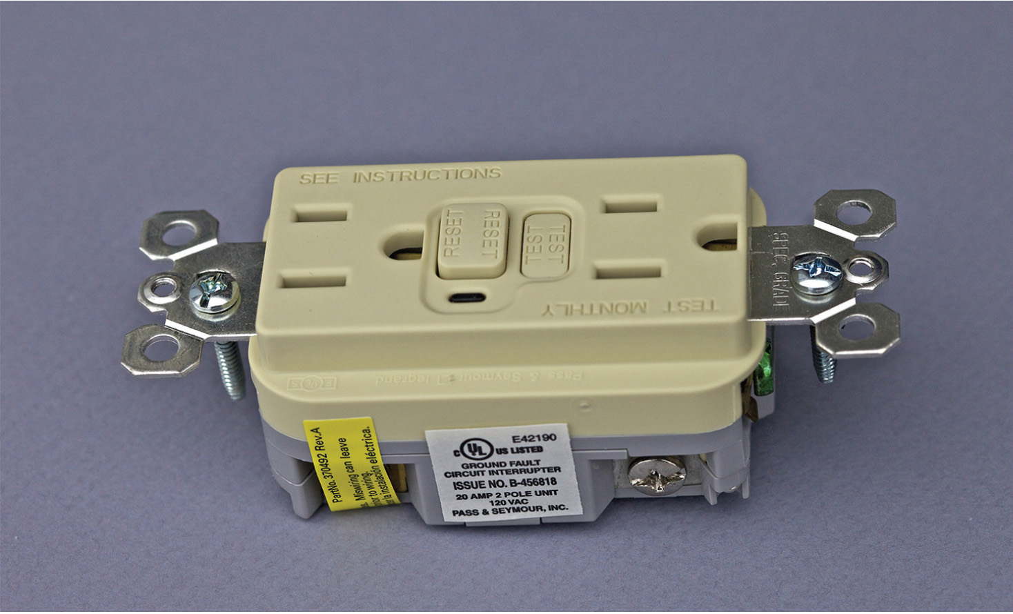
FIGURE 5-2 The receptacle-type GFCI device has feed-through capability so that conventional downstream receptacles can be protected.
• Section 210.8(A)(9), “Ground-Fault Circuit-Interrupter Protection for Personnel. Dwelling Units. Bathtubs or Shower Stalls.” All 125-volt, single-phase, 15- and 20-ampere receptacle outlets in bathrooms and those outside the bathroom that are within 6 feet of the edge of a bathtub or shower stall are to be GFCI protected.
• Section 210.8(A)(10), “Ground-Fault Protection for Personnel. Dwelling Units. Laundry Areas.” All receptacle outlets in dwelling-unit laundry areas require GFCI protection, including the outlet for the washing machine. These GFCI receptacles in the laundry area must be readily accessible.
• Section 210.8(D), “GFCI Protection. Kitchen Dishwasher Branch Circuit.” In dwelling units, kitchen dishwasher outlets are to have GFCI protection.
Arc-Fault Protection
• Section 210.12(A), “Arc-Fault Circuit-Interrupter Protection. Dwelling Units.” Arc-fault circuit-interrupter (AFCI) protection has been extended to include kitchen and laundry areas. These areas have been added to the previous list, which included family rooms, dining rooms, living rooms, parlors, libraries, dens, bedrooms, sunrooms, recreation rooms, closets, hallways, and the like. In dwellings, AFCI protection is not required in bathrooms, garages, crawl spaces, attics, and outdoors.
• Section 210.12(A)(1)–(16), “Arc-Fault Circuit-Interrupter Protection. Dwelling Units.” Besides simply installing a listed combination-type AFCI in the entrance panel or load center to protect the entire branch circuit, there are other methods that are Code compliant:
• Install an outlet branch circuit–type AFCI receptacle as the first outlet on the branch circuit. The run between the circuit breaker and the first outlet must be rigid metal conduit (RMC), intermediate metal conduit (IMC), electrical metallic tubing (EMT), metal-clad cable (MC), or steel armored cable (AC), and the outlet and junction boxes must be steel.
• Install an outlet branch circuit–type AFCI receptacle as the first outlet on the branch circuit, with the raceway from the circuit breaker to the first outlet encased in not less than 2 inches of concrete.
These are the traditional (2011 NEC) methods of achieving AFCI protection. Where an in-panel AFCI breaker (which is very expensive) is not used, equivalent protection in the form of raceway, concrete encasement, or length limitation is provided for the conductors that are not AFCI protected.

FIGURE 5-3 Type NM cable, at left, has many uses, such as powering a hot-water heater or submersible well pump for a home.
The 2014 NEC offers added options:
• Install a listed branch-circuit/feeder-type AFCI breaker and a listed outlet-type branch-circuit AFCI receptacle as the first outlet on the circuit. The first outlet box must be marked to show that it is the first outlet on the circuit.
• Install a listed supplemental arc-protection circuit breaker with a listed outlet branch circuit–type AFCI receptacle as the first outlet on the circuit, with conditions.
• Install a listed outlet branch circuit–type AFCI as the first outlet on the branch circuit in combination with a listed circuit breaker, with conditions.
The point of these alternatives is to save the expense of buying the breaker-type AFCI. After all, at a discount source, they still cost over $35, and at one for each branch circuit in a residence that requires AFCI protection, this adds substantially to the price of building a new home or large addition. However, how much will be saved unless the first receptacle is very close to the entrance panel?
Some More 2014 NEC Changes
• Section 210.17, “Electric Vehicle Charging Circuit.” Outlets installed for the purpose of charging an electric vehicle are to be on a separate dedicated circuit with no other outlets.
• Section 210.52(E)(1), “Outdoor Dwelling-Unit Receptacles.” The outdoor receptacles, required at the front and back of each residence, no longer have to be accessible from grade level, so if one or both of them are accessible only from a deck, that will meet the requirement. In wiring a new home or addition, don’t neglect to provide for the two outdoor receptacles, whether accessible from grade level or not.
• Section 210.52(G), “Receptacle Outlets, Basements, Garages, and Dwelling Units.” In an attached garage or a detached garage with electric power, at least one receptacle outlet must be installed for each car space, and the branch circuit supplying these outlets cannot supply other outlets outside the garage. The underlying principle of these new requirements is that a garage that is attached to a residence must be connected to the premises wiring, whereas power for a detached garage is optional.
Wet-Location Receptacles
• Section 406.9(B)(1), “15- and 20-Ampere Receptacles in Wet Locations.” The 2014 NEC requires all 15- and 20-ampere receptacles in wet locations to have extraduty covers. The 2011 NEC required in-use covers, but they were found to break easily and not to perform their intended function of keeping water out of the receptacles when cords were plugged into them. The new extraduty covers are more durable and are now required.
• Section 406.12, “Tamper-Resistant Receptacles.” Tamper-resistant receptacles are required for nonlocking 125-volt, 15- and 20-ampere receptacles in dwellings. They are not required under the following conditions:
• Where receptacles are more than 5½ feet above the floor
• Where receptacles are part of a luminaire (light fixture) or appliance
• Where it is a single or duplex receptacle for two appliances located within a dedicated space and not easily moved
• Where it is a nongrounding receptacle used as a replacement
The purpose of tamper-resistant receptacles is to protect naturally inquisitive children from inserting conductive objects into the receptacles, resulting in electric shock.
These are the principal 2014 NEC changes that apply to residential work. Besides being important to promote electrical safety, they should be incorporated, where relevant, into any electrical installation because the inspectors focus intently on these new requirements.
Some Definitions
There are perennial definitions, existing language that reappears in each new Code edition with a word changed here and there but substantially the same. Here are the principal terms that pertain to residential work and are of greatest importance for the home crafter-electrician:
Throughout the NEC we encounter the terms accessible, readily accessible, and concealed. They are significant because, throughout the NEC, many electrical devices and types of equipment are required to be located in, permitted in, or prohibited from these locations, so first you need to know how to delineate them.
Accessible, as applied to equipment, means admitting close approach, not guarded by locked doors, elevation, or other effective means. Accessible, as applied to wiring methods, means capable of being removed or exposed without damaging the building structure or finish or not permanently closed in by the structure or finish of the building. Readily accessible means capable of being reached quickly for operation, renewal, or inspection without requiring those for whom ready access is necessary to use tools, to climb over or remove obstacles, or to resort to portable ladders and so forth.
This distinction, for the most part, is easy to understand, but gray areas are possible, and in such instances, the judgment is to be made by the electrical inspector. An example of a location that is accessible but not readily accessible is the space above a suspended ceiling. A switch adjacent to a room entry that controls a ceiling light must be readily accessible, and of course, this is a profound safety issue when, to mention one example, there is a fire and rescue workers have to check rooms.
All splices in electrical wiring must be accessible but need not be readily accessible. Junction boxes containing electrical splices are not to be concealed behind finish walls or ceilings. This is a long-standing NEC violation and interferes greatly with troubleshooting and repair. Such enclosures used to be called blind boxes, but the term is no longer used out of respect for the visually impaired.
A related concept is concealed, which means rendered inaccessible by the structure or finish of the building. Various types of wiring are required, permitted, or prohibited from being concealed, and to disregard one of these provisions is a definite Code violation. If it is caught by an inspector, expensive rework may be required, and if the problem is not detected, there could be a hazardous situation at some time in the future.
A bathroom is defined as an area including a basin with one or more of the following: a toilet, a urinal, a tub, a shower, a bidet, or similar plumbing fixtures. According to this definition, a simple washroom with only a sink and mirror would not be considered a bathroom, and therefore, the entrance panel could be located there.
Similarly, a clothes closet is defined as a nonhabitable room or space intended primarily for storage of garments and apparel. If there is a problem finding a location for the entrance panel, it may be possible to repurpose a clothes closet, but in that case, clothes and apparel would have to be kept out of the room or area. Also, dedicated space and clear working space would have to be verified.
A kitchen is defined as an area with a sink and permanent provisions for food preparation and cooking. The presence of a microwave oven in a room would not in itself constitute a kitchen, and this distinction would be decisive in determining whether to provide GFCIs and the two 20-ampere small-appliance circuits.
A very basic requirement for all electrical wiring, residential, commercial, or industrial, appears in Section 110.26, “Spaces about Electrical Equipment.” It provides that access and working space are to be provided and maintained about all electrical equipment to permit ready and safe operation and maintenance, as shown in Table 5-1.
TABLE 5-1 Minimum Clear Distances (Depths) for Various Conditions and Voltages to Ground

Two voltage categories, 0–150 and 151–600, appear in the left column. The table provides minimum distances for three conditions:
• Condition 1. Where exposed live parts are on one side of the working space and no live or grounded parts are on the other side of the working space or exposed live parts are on both sides of the working space that are effectively guarded by insulating materials.
• Condition 2. Where exposed live parts are on one side of the working space and grounded parts are on the other side of the working space. Concrete, brick, or tile walls are considered grounded.
• Condition 3. Where exposed live parts are on both sides of the working space.
Notice that Table 5-1 applies to the depth of the working space. The width of the working space is a different matter. It is the width of the equipment or 30 inches, whichever is greater. Most electrical equipment that falls into this category in residential settings (e.g., entrance panels and smaller disconnecting means) is less than 30 inches wide, so the required width of the working space is generally 30 inches. If two or more enclosures are mounted side by side, they may share this space. Moreover, a box need not be centered in the working space as long as the entire enclosure is within it.
The working-space requirement is entirely separate from the dedicated space above equipment, and both of these must be met, both indoors and outside. A Code violation is shown in Figure 5-4. The purpose of the dedicated space is to ensure that the equipment can be installed and will function properly, whereas the clear-working-space requirement focuses on worker safety. The height of the working space is to be the height of the equipment or 6½ feet above the grade, floor, or platform, whichever is higher.

FIGURE 5-4 Note the clear violation of working-space requirements.
NEC Chapter 1, “General,” as we have seen, contains fundamental rules that are applicable to all electrical installations. Chapter 2, “Wiring and Protection,” continues in this mode, and we shall go through it, extracting the material that is applicable to residential work.
Color-Coding Details
NEC Chapter 2 opens with a discussion of color-coding. In doing any electrical project, it is essential that the correct color be used for each and every conductor. This is necessary so that the electrician can keep track of what is being done, as well as to facilitate any future maintenance, repair, or additions to the wiring system.
The basic idea behind color-coding—black is hot, white is ground—is very simple, but in actual practice, there are subtle distinctions and exceptions that need to be noted. From the point of view of safety and functionality, the most fundamental distinction is between grounded and ungrounded conductors. Grounding conductors (which are at the same voltage potential as grounded conductors but serve a different purpose) are color-coded differently so that they can be distinguished.
The method for identifying grounded conductors depends on the size. If the conductor is 6 American Wire Gauge (AWG) or smaller, an insulated grounded conductor must be white or gray or have three continuous white stripes in other than green insulation. Some years ago, the NEC referred to natural gray insulation, but that term was discontinued because it would imply that there was such a thing as “unnatural gray” that could not be used to denote a grounded conductor. Gray may have been used in the past to label ungrounded conductors, so care must be used in working on older systems.
It is not permitted to reidentify an ungrounded conductor as grounded for 6 AWG and smaller wires, except for mineral-insulated metal-sheathed cable (Type MI), single-conductor photovoltaic outdoor-rated sunlight-resistant wire, and fixture wire. Aerial cable can have a ridge along its entire length to denote that it is grounded.
In sizes larger than 6 AWG, there are different NEC rules. The reason is that it would not be practical to stock these larger sizes in all colors. There would be a greater amount of waste, with numerous useless cutoffs instead of one for each job. Conductors larger than 6 AWG may be reidentified as white at terminations only, so it is possible to make use of black wire for any of the conductors. To reidentify, use white paint or, preferably, white phase tape. This must completely encircle the conductor, but it is not necessary to make more than one ring. When grounded conductors pass through an enclosure without termination, reidentification is not required.
For conductors of any size, an insulated grounded conductor in a flexible cord may be identified by a white or gray outer finish, white or gray braid or white or gray tracer in the braid, or a white or gray separator. If in a cord the insulation is integral with the jacket, individual tinned strands will suffice to identify the grounded conductor. Also, ridges, grooves, or white stripes on the outside of a cord will serve to identify a grounded conductor.
If more than one system is included in an individual raceway, cable, or enclosure, each grounded conductor is required to be identified separately, and each of them must conform to the preceding requirements. This coding is to be posted at all branch-circuit panel boards. Although it is not required by the NEC, the general trade practice is to use white for the lower-voltage and gray for the higher-voltage grounded conductors.
In switch loops, white wires may be used as ungrounded conductors, but they must be reidentified by marking them black. At one time, the white ungrounded conductor inside the switch enclosure did not have to be reidentified because this was considered self-evident. Current editions of the NEC require that both ends of the white conductor in a switch loop be reidentified. In many but not all instances, this has become a moot point because an unused white neutral is required in switch-loop enclosures for future use, and 14-3 Romex is used, but there are exceptions where 12-2 Romex persists, and this is where the reidentification is necessary.
Bare and Green Wires
Equipment-grounding conductors are identified differently. They originate in the entrance panel, connected to the neutral by means of the main bonding jumper. From there they accompany the other conductors to each outlet, never again to be electrically connected to the grounded conductors.
Grounding conductors may be bare or insulated. If they are insulated, the color is green. Like grounded conductors, grounding conductors larger than 6 AWG are permitted to be reidentified. This may be accomplished by stripping the insulation from the entire length, in effect converting the conductor to bare, or by coloring the insulation green using paint or, preferred, phase tape. The reidentification must entirely encircle the conductor as opposed to making just a spot. This reidentification is not required in enclosures such as conduit bodies that contain no splices. In flexible cord, a bare conductor qualifies. If it is insulated, the color must be green.
For ungrounded, so-called hot wires, conductors must be clearly distinguishable from grounded and grounding conductors. Accordingly, they may be any color but white, gray, or green and, of course, never bare. When installing wire in raceways, it is possible to pull whatever colors are required. In residential work, Romex is generally used, and you have to work with the colors that are available. For this reason, reidentification may be needed.
Article 210, “Branch Circuits,” contains many provisions that pertain to residential installations, and before doing any wiring, the home crafter-electrician should go through this article carefully. Section 210.3, “Rating,” states that the ratings for other than individual branch circuits are 15, 20, 30, 40, and 50 amperes. Outside the service, these are the sizes most used in residential work. It is to be emphasized that circuit ratings are determined by the overcurrent device rating, and the conductor size follows from that, as set forth in NEC Chapter 3. If, for any reason, for example, to mitigate voltage drop, it is decided to go to a larger wire size, this is permissible because the Code-mandated wire sizes are minimum wire sizes. In such cases, however, the circuit size does not change. It is still determined by the overcurrent device rating.
NEC Section 210.4 permits the use of multiwire branch circuits. Some electricians make very extensive use of them because they allow for significant savings in materials and labor. A multiwire branch circuit is characterized by the use of a single grounded (white) conductor as the neutral for two separate circuits with different ungrounded (black and red) conductors. The grounded conductor may be thought of as a shared neutral. All three are contained in a single cable or raceway, in residential work usually 12-3 or 14-3 Romex.
The two hot wires, black and red, are protected against overcurrent at 15 or 20 amperes, and for this reason, each of them, along with the neutral that they share, comprises a separate individual branch circuit. If each of these hot wires were to be loaded close to ampacity, let us say at the full 15-ampere rating of the circuit, would not the neutral be overloaded at 30 amperes so that it could become red hot in a wall cavity and ignite nearby combustible material or at the least undergo insulation damage?
The answer is no. In a properly constructed multiwire branch circuit, the two hot wires are connected to the opposite phase legs in the entrance panel or load center. Because the two neutrals are 180 degrees out of phase, the smaller is subtracted from the larger to find the current on the common neutral conductor. If the two loads are each 15 amperes or any other equal quantities, the current on the single neutral will be 0 amperes. The maximum current in the common neutral occurs when the load on one circuit is maximum, 15 amperes in this example, and the load on the other is 0 amperes. In this situation, the current in the shared neutral is 15 amperes, which is not a hazardous overload.
Several savings result from the use of a multiwire branch circuit. First is the obvious savings in wire, because a single white conductor serves as the neutral for two circuits. Also, there is a savings in certain hardware because a single cable connector, run of staples, and so on is needed.
In a raceway system, there is less conduit fill, which may translate into a smaller raceway size. There is less labor in the conduit pull. In a cable system, there is less labor because one cable run replaces two, with less drilling of studs and fewer terminations to be made. Moreover, the round three-wire cable is easier to run than the flat two-wire cable because you don’t expend so much effort preventing cable twists. For these reasons, some of the high-volume electrical contractors favor the use of multiwire branch circuits where they are permitted. A few dollars saved on every job adds up to a fortune in the life of a company.
There is a major downside to multiwire branch circuits, and this is why many of the better electricians will not use them. If, in the future, in the course of repair or alterations, a less knowledgeable worker shifts one of the hot legs to the wrong phase in a panel, the currents in the neutral suddenly will become additive, and there is the possibility that loaded beyond its overcurrent protection, that neutral will overhead and ignite nearby combustible material.
The NEC recognizes the potential for this hazard and rules are in place to mitigate it:
Each multi-wire branch circuit is to be provided with a means that will simultaneously disconnect all ungrounded conductors at the point where the branch circuit originates. This is usually a double-pole breaker, as normally used for a 240-volt circuit. Two single-pole breakers with a listed handle tie to ensure that they trip simultaneously will serve the purpose, but the usual procedure is to use a double-pole breaker. Under no circumstances is an improvised expedient such as a nail or piece of wire through the holes in the single-pole breakers to be substituted.
Another NEC safeguard for multiwire branch circuits is the requirement in Section 210.4(D), “Grouping,” which states that the ungrounded and grounded circuit conductors of each multiwire branch circuit are to be grouped by cable ties or similar means in at least one location within the panel board or other point of origination.
These rules are designed to ensure that the two hot legs of a multiwire branch circuit will not be connected to the same phase in the future. But a little knowledge is dangerous, and in the fullness of time, it is a distinct possibility that a partially trained worker will swing one of the phase wires over to the wrong leg. So it is not recommended that the home crafter-electrician use multiwire branch circuits in the initial installation.
Ampacities and Device Ratings
NEC Chapter 2 moves on to lay out some additional requirements that apply to residential electrical installations. Branch circuits, unless otherwise specified, are to have an ampacity sufficient for the loads served and are not to be smaller than 14 AWG. Where a branch circuit supplies continuous loads or any combination of continuous and noncontinuous loads, the rating of the overcurrent device is to be not less than the noncontinuous load plus 125 percent of the continuous load. Table 210.21(B)(3), “Receptacle Ratings for Various Size Circuits,” presents information that is somewhat counterintuitive, as shown in Table 5-2.
TABLE 5-2 Circuit Ratings for Various Size Circuits
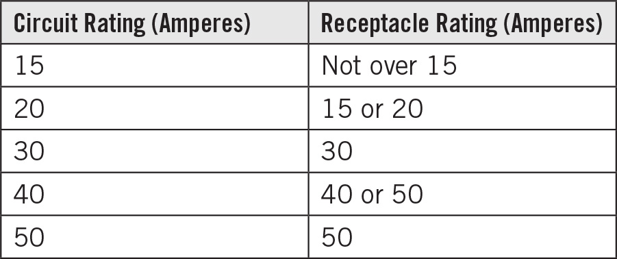
We ordinarily believe that the overcurrent device should be the weakest link in the chain so that it will shut down the circuit before any other parts of it are stressed. As a rule, this is true, but there are many exceptions throughout the Code, and among them are receptacle ratings. One of the most important of them is the fact that a 15-ampere receptacle is permitted on a 20-ampere circuit. As mentioned previously, many electricians use 12 AWG copper Romex for almost all residential circuits, even when the loading would allow for 14 AWG copper Romex. Then there is the option to use 15- or 20-ampere breakers for overcurrent protection. The 15-ampere breaker is more sensitive, offering more robust overcurrent protection, whereas the 20-ampere breaker is more resistant to nuisance tripping, permitting the full benefit of the 12 AWG copper Romex, which has higher ampacity. Table 210.21(B)(3) permits 15-ampere receptacles, shown in Figure 5-5, to be used with either size circuit.

FIGURE 5-5 Receptacles are available in 15- and 20-ampere ratings as well as other sizes.
Chapter 2, Part III, “Required Outlets,” goes into considerable detail concerning required receptacle placement and spacing within a residence. In wiring habitable rooms, laundries, bathrooms, and kitchens, it is necessary to have this part of NEC Chapter 2 before you and to use it as a checklist to make sure that everything is in place.
NEC Chapter 3, “Wiring Methods and Materials,” continues the coverage of general principles underlying all electrical work, as seen in Chapters 1 and 2. A lot of this material pertains to residential wiring, and we shall summarize the topics that are of interest to the home crafter-electrician
Section 300.5, “Underground Installations,” contains information needed to build an underground service. Also, the time may come when you will want to bury an electrical feeder that supplies power to an outbuilding, outdoor light fixture, septic pump, or outdoor power outlet that is not attached to a building. You will need to refer to Table 300.5, “Minimum Cover Requirements.” All parts of this table except for the bottom row are relevant to residential electrical work. Notice that there is not an entry specific to services. However, utilities specify burial depths and other requirements.
Notice that where conductors are placed in RMC, minimum cover is reduced to as little as 6 inches (or even 4 inches with concrete), so this is helpful where bedrock is encountered. Some types of wires, either individual conductors or in cable, are rated for direct burial without raceways. An example is underground feeder (Type UF). The preferred installation, however, is in conduit, usually polyvinyl chloride (PVC). This arrangement has the advantage that if conductor replacement becomes necessary, it can be done without digging, simply by pulling in new wire.
If the conductors are buried directly, they still must be protected by raceways where they emerge from grade either to where they enter the building or to a height of 8 feet above grade. The best way to bring buried conductors into a building is to have them emerge from underground and enter the building through a Type LB fitting, as shown in Figure 5-6, as opposed to going through a hole in the concrete.

FIGURE 5-6 Type LB is one of several types of conduit fittings that facilitate conductor pulls and make angle turns.
The interiors of enclosures or raceways installed underground are considered to be wet locations, so suitable conductors and splicing methods are required. If moisture can enter and contact live electrical parts, the raceway is to be sealed at either or both ends. In addition, raceways are to be provided with expansion joints if needed to compensate for thermal expansion and contraction.
Article 310, “Conductors for General Wiring,” is perhaps the most referenced part of the entire NEC. With its many tables pertaining to conductor sizing, it is not practical to memorize individual requirements, nor is this necessary because the Code can be used on an open-book basis.
The heart of Article 310 is a series of tables, 310.15(B)(16) through 310.15(B)(21). They are used to size conductors in most electrical installations, and only by understanding and applying the tables with accompanying notes can we be certain that the wires have sufficient ampacity to carry the current without overheating.
Each of these tables has a lengthy heading that details the conditions for which the table is applicable. By far the most used is Table 310.15(B)(16). This table gives allowable ampacities, the maximum current that can be carried safely without danger of overheating. The table applies to insulated conductors rated up to and including 2,000 volts, rated 60 through 90°C, where there are not more than three current-carrying conductors in raceway or cable or buried directly in earth, based on an ambient temperature of 30°C.
Other tables in this series give ampacities for over 2,000 volts and for free conductors in air, that is, aerial installations. It is the first table, though, that is applicable for most residential jobs. Most of the time, you will use this table in reverse, beginning with the ampacity that will be needed, then working back to the top row to choose the type of conductor that is to be used, and then proceeding to the column at the far left. It will tell you, above all, what you need to know, which is the correct wire size.
The process is quite simple once you have chosen the correct table based on the criteria in the heading. The left half of the table contains ampacities for copper conductors, and on the right are aluminum conductor ampacities, rarely used in residential work except for services. Also, for residential work, you will be referring to the top half of the table for conductor sizes not over 4/0 AWG. This is all there is to choosing wire size, except that before beginning, there are operations to be performed in the course of finding the desired ampacity, which is the maximum current the conductor will be required to carry.
Correction and Adjustment Factors
First, determine the load. Obtain the total based on the general lighting load from NEC Table 220.12, as explained earlier, and the nameplate rating or marking on any equipment that will comprise the load. To this amount, various derating factors may be applied, as explained in our coverage of NEC Chapter 2.
The quantities so determined are matched up to the ampacities in Table 310.15(B)(16) or other applicable table so as to find the required conductor size for the wire type that is to be used. Before the final decision can be made, though, it is necessary to alter the ampacity to suit certain conditions pertaining to the installation. This involves, where necessary, multiplying the ampacity successively by one or more numbers that are given in NEC tables. These numbers are less than 1 (i.e., percentages) that cause the ampacity to become lower, meaning that you may have to choose a larger conductor size to provide the minimum required ampacity. Because the factors are multipliers, the order in which they are applied does not matter. We will discuss them in the order in which they appear in the NEC. See Table 5-3.
TABLE 5-3 Ambient Temperature Correction Factors

Table 310.15(B)(2)(a), “Ambient Temperature Correction Factors Based on 30°C,” provides multipliers that are used to reduce the ampacity so that in some cases larger conductors are needed. The ampacities given in Table 310.15(B)(16) are to be multiplied by the factors shown in this table before choosing the conductor size. Because this particular ampacity table, shown in Table 5-3, is based on an ambient temperature of 30°C, we use these correction factors rather then those in Table 310.15(B)(2)(b), which is based on 40°C. In other words, be certain that both tables are based on the same ambient temperature or the results will not be valid.
Temperature correction factors must be applied when conductors, not necessarily the load, are exposed to high-temperature surroundings somewhere along the line, for example, when a branch circuit is routed near a heat source such as a furnace or uninsulated heat duct. The high ambient temperature will interfere with dissipation of heat due to current carried by the conductor, making for an increase in temperature. The result, if conductor size is not increased, could be fire hazard and/or damage and premature failure of the conductor insulation. By applying the correction factor, which may dictate a larger conductor size, the hazard is mitigated.
Table 310.15(B)(3)(a), “Adjustment Factors for More than Three Current-Carrying Conductors,” shown in Table 5-4, gives another factor that sometimes must be applied to the ampacity so that conductors can be chosen that will not experience heat rise.
TABLE 5-4 Adjustment Factors When More than Three Current-Carrying Conductors Are Used
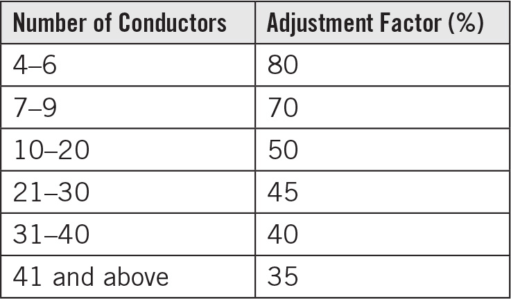
The accompanying notes provide interpretations on how to apply the table. The question that arises is how to determine whether or not a conductor is to be considered current-carrying.
Equipment-grounding and bonding conductors are not counted as current-carrying conductors. Neutral conductors that carry only the unbalanced current from other conductors of the same circuit are not required to be counted as current-carrying conductors. Conductors that are connected to electrical components but cannot be simultaneously energized are not required to be counted. Spare conductors must be counted. Adjustment factors are not required to be applied to conductors in raceways having a length not exceeding 24 inches.
The temperature factors are known as correction factors. For conductor count, the factors are known as adjustment factors. This difference in semantics helps to distinguish the two types of multipliers. They are both derived from their respective tables and are applied in the same way to the ampacities in the Chapter 3 ampacity tables.
Box-Fill Calculations
Article 314, “Outlet, Device, Pull, and Junction Boxes; Conduit Bodies; Fittings; and Hand Holes,” contains box-fill rules. The basis for these rules is the statement that boxes and conduit bodies are to be of a size to provide free space for all enclosed conductors. In no case is the volume of the box as calculated in Section 314.16(A) to be less than the fill as calculated in Section 314.16(B).
Boxes and conduit bodies enclosing 4 AWG or larger conductors are figured differently and must comply with Section 314.28. These sizes are rarely seen in residential work except in services, which are not spliced.
Boxes that are overfilled create a severe hazard, and this is a source of difficulty in many faulty installations. Where physical force must be used to get all the conductors into a junction box so that the cover can be attached or to pack the conductors into a wall box so that a switch or receptacle, particularly a GFCI (because it is larger), can be bolted into place, there is the possibility that the conductors will be damaged or the termination will be loosened or pulled apart. Then there is a chance of an arcing fault, or the device or load could stop working in the future. Wire nuts, shown in Figure 5-7, especially if they are used to join more than two conductors, are prone to eject conductors when forced into an overcrowded box.

FIGURE 5-7 Wire nuts contribute to box fill and must be factored into the equation.
Electricians quickly get a sense of what will go into a box, but in borderline cases or unusually large boxes, it is possible to make a mistake. Use of deep wall boxes and 4 × 4 square boxes, as shown in Figure 5-8, rather than octagonal junction boxes is helpful. The problem is that when it is time to terminate the device and insert it into or on the box along with associated wiring and devices, the finish wall or ceiling material is already in place, and it is not possible to replace the box with a larger one without tearing out the finish material.
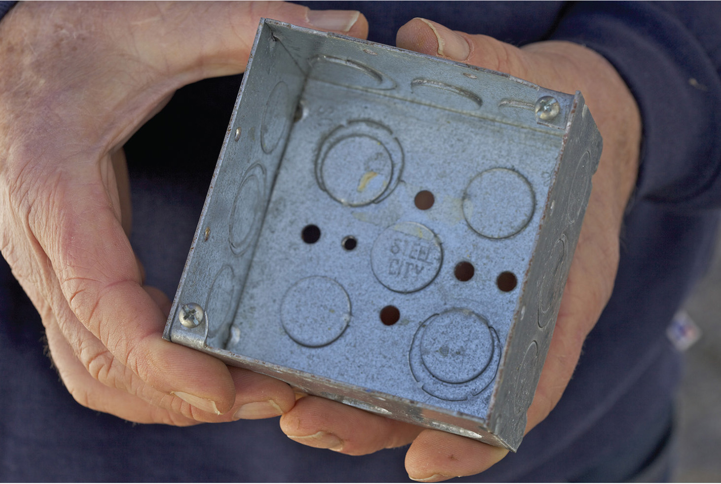
FIGURE 5-8 Large enclosures make for less box fill so that the installation is compliant and there is no chance of conductor damage.
The remedy for this sort of problem is to perform the box volume and fill calculations so as to determine prior to installation whether a proposed box size is suitable for the intended use. Section 314.16(A), “Box Volume Calculations,” states that the volume of a wiring enclosure (box) is to be the total volume of the assembled sections and, where used, the space provided by plaster rings, domed covers, extension rings, and so forth, which are marked with their volume or are made for boxes the dimensions of which are listed in Table 314.16(A), “Metal Boxes.”
Section 314.15(B), “Box-Fill Calculations,” contains five paragraphs that describe how to calculate the box fill of various types of hardware. Some small fittings, such as locknuts and bushings, require no fill allowance.
Table 314.16(B), “Volume Allowance Required per Conductor,” lists an amount for each conductor. All you have to do is make a list of what is to go into the box and determine the size of the box needed.
The rest of Chapter 3 is made up of Articles 320 through 399, which cover specific varieties of cable and raceways. The articles follow a common organizational template, making them easy to navigate. Articles 320 through 340 cover cable types in alphabetical order. These are followed by raceways, which are subdivided into types of tubing and conduit, but they are not in alphabetical order. Finally, there are four additional kinds of wiring.
The best way to find the article that covers a desired type of cable or raceway is to look it up in the Table of Contents at the beginning of the NEC. Some of the cable and raceway types are used very frequently, and you will quickly learn the article numbers that pertain to them, for example, Type NM (Romex), which is covered in Article 334.
NEC Chapter 4, “Equipment for General Use,” contains articles on specific devices and equipment such as switches, receptacles, light fixtures, appliances, fixed space heating, motors, air-conditioning equipment, and so forth. A lot of this material has to do with construction specifications and is of interest primarily to manufacturers. Some sections, such as Article 430, “Motors, Motor Circuits, and Controllers,” pertain to industrial facilities, and there is little relevance to residential work. The home crafter-electrician, however, will want to take a good hard look at some parts of Chapter 4, for example, Section 410.16, “Luminaires in Clothes Closets” (luminaire is the Code term for a light fixture).
A light fixture inside a clothes closet is a potential fire hazard because the stored clothing is highly flammable, and the luminaire is a source of heat, both in normal operation and in the case of a malfunction where sparks may be emitted. Section 410.16 contains a detailed list of clearances that must be observed during the initial installation. In some closets, because of limited size, it is impossible to comply with these clearances. In such cases, there is the option of installing a battery-powered closet light, made for the purpose, that is incapable of igniting nearby combustible materials. Another work-around is to position a ceiling light just outside the closet in the adjoining room.
Section 410.16 contains a detailed diagram showing all clearances. The basic clearances between luminaires and the nearest point of closet storage space are
• Twelve inches for surface-mounted incandescent or light-emitting-diode (LED) luminaires with a completely enclosed light source installed on the wall above the door or on the ceiling
• Six inches for surface-mounted fluorescent luminaires installed on the wall above the door or on the ceiling
• Six inches for recessed incandescent or LED luminaires with a completely enclosed light source installed in the wall or ceiling
• Six inches for recessed fluorescent luminaires installed in the wall or ceiling
• Surface-mounted fluorescent or LED luminaires are permitted to be installed within the closet storage space where identified for this use.
NEC Chapter 4 goes on to cover some other types of equipment for general use. Still on the topic of luminaires, there are parts of the article that are concerned with supports. A luminaire that weighs over 6 pounds or exceeds 16 inches in any dimension is not to be supported by the screw shell of a lamp holder. Another issue regarding the installation of luminaires is grounding. All exposed normally nonconducting metal parts are to be mechanically attached to the equipment-grounding conductor that accompanies the branch circuit.
After the wiring has been roughed in and wall and ceiling materials are in place, we are ready to start the electrical finish work. A good part involves hanging the wall and ceiling light fixtures. If they are new, there will be a complete set of installation instructions, so if there is any question concerning electrical connections or mechanical mounting, there will be an answer. Most of this is self-evident. If the light fixture is a heavy chandelier, a helper will be needed to support it while you wire nut the electrical connections prior to mounting it to the ceiling.
It is stated in this article that wiring on or within luminaires is to be neatly arranged and not exposed to physical damage. Excess wiring is to be avoided. Conductors are to be arranged so that they are not exposed to temperatures above those for which they are rated.
Many incandescent luminaires come with labels stating a maximum size bulb to be used, often 60 watts. This warning should be observed because the heat from a larger bulb can char nearby combustible material, progressively lowering the ignition temperature.
Section 410.50, “Polarization of Luminaires,” such as the combination paddle-fan light fixture shown in Figure 5-9, states that the grounded conductor, where connected to a lampholder, is to be connected to the screw shell.
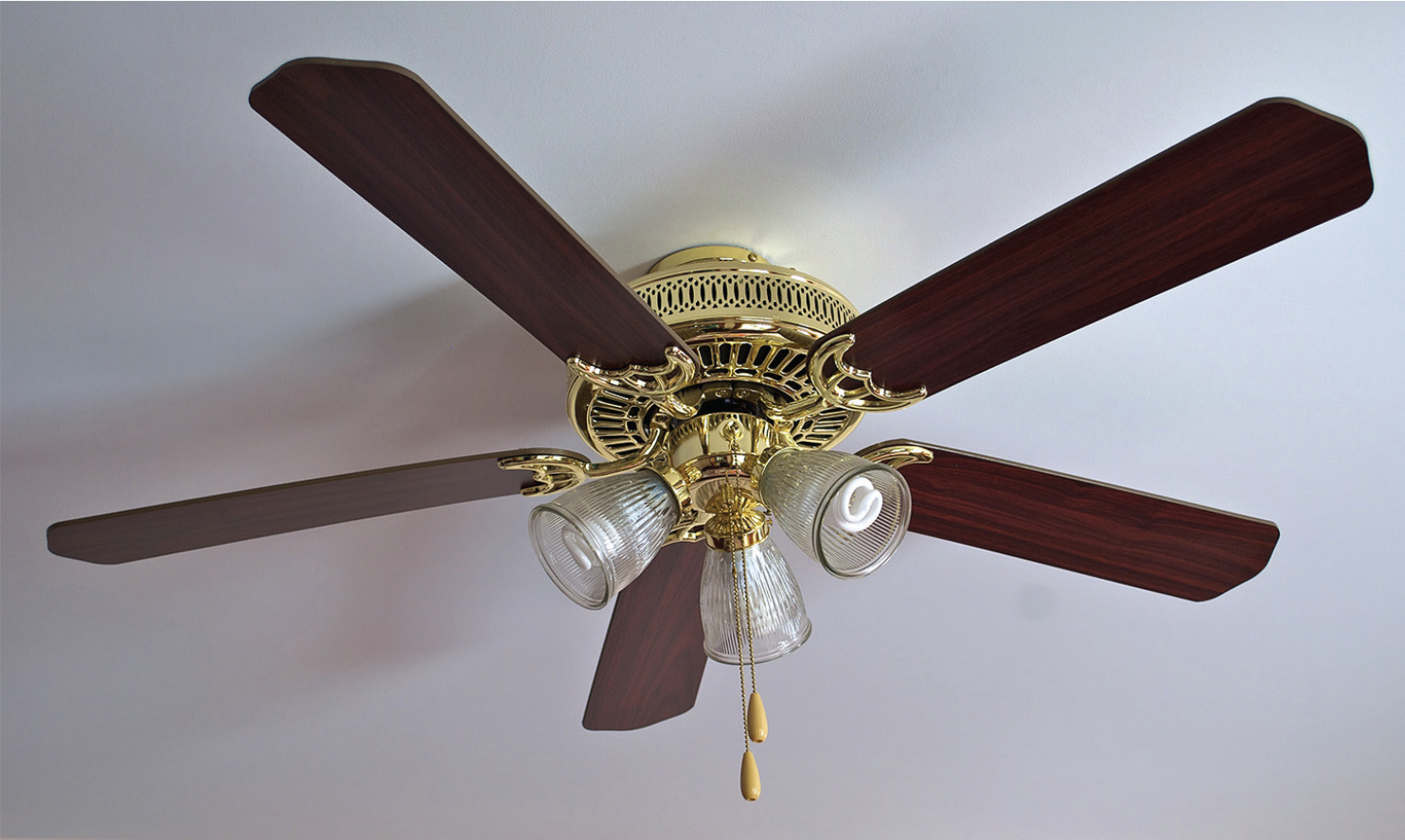
FIGURE 5-9 A paddle-fan luminaire requires special mounting arrangements to make sure that it is secure. Consult the manufacturer’s documentation before installing the ceiling box.
The installation, when completed, should consist of the equipment-grounding conductor connected to the outer housing and the grounded conductor connected to the screw shell. These two parts are to be insulated from each other so that there is no electrical connection between grounded conductor and grounding conductor downstream from the entrance panel, where they are joined by the main bonding jumper (unless there is a main disconnect in a separate enclosure still farther upstream). Such a connection would violate one of the most basic principles of all grounded wiring systems. Under no circumstances is the hot (black) conductor to be connected to the screw shell or to the fixture housing.
Article 422, “Appliances,” covers this type of equipment, defined in Article 100, “Definitions,” as utilization equipment, generally other than industrial, that is normally built in standardized sizes or types and is installed or connected as a unit to perform one or more functions, such as clothes washing, air conditioning, food mixing, deep frying, and so forth. A typical home appliance is shown is Figure 5-10.

FIGURE 5-10 NEC Article 422 covers appliances such as this home refrigerator.
An appliance may be portable or fixed, and it may be hardwired or cord-and-plug connected. Some appliances, such as an electric range with oven or a tankless hot-water heater, shown in Figure 5-11, consume significant amounts of power and are among the largest loads in a home. Others, such as an electric refrigerator, consume modest amounts of power and may be connected to an ordinary 15-ampere branch circuit.
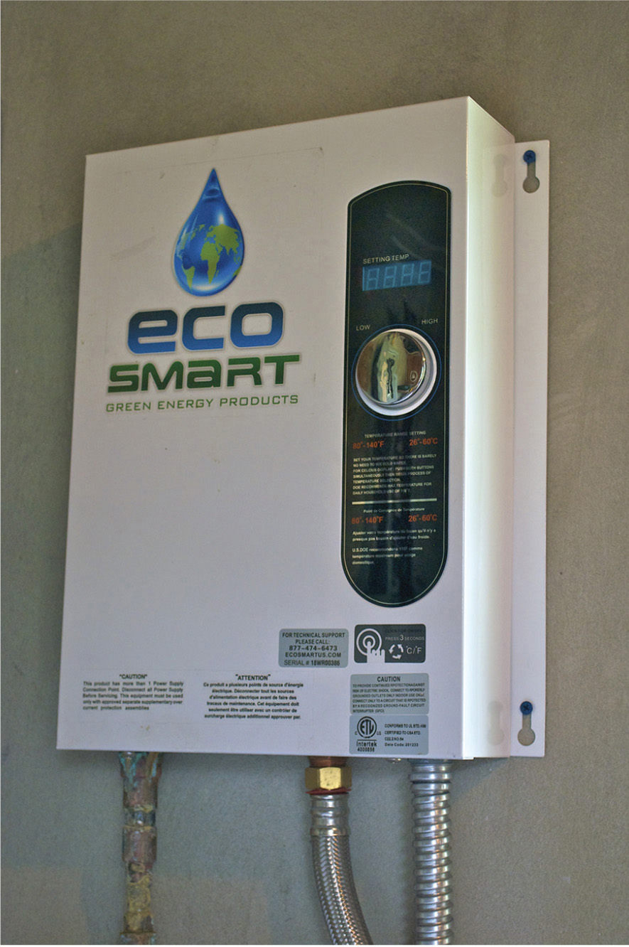
FIGURE 5-11 A tankless (quick-recovery) hot-water heater draws more current but for shorter durations than a conventional hot-water heater.
A key provision of this article is that the branch-circuit rating for any appliance other than a motor-operated appliance that is a continuous load is to be 125 percent of the marked rating. Continuous is defined as expected to operate for 3 hours. A fixed storage-type water heater that has a capacity of 120 gallons or less is to be considered a continuous load for the purpose of sizing branch circuits.
Appliance Identification
To wire an appliance, you need to find the rating of the unit. This will appear on the nameplate. The nameplate is a small metal label that is permanently attached to the appliance. It is usually on the back, inside a door, or at some other location that is not difficult to find. Always begin with the nameplate.
The nameplate contains certain information that is prescribed by the NEC. This information differs depending on the type of equipment. Motor nameplates always state the revolutions per minute (rpms), but this is obviously not relevant for many appliances. The nameplate of a typical quartz infrared portable heater states the name of the manufacturer; the voltage, frequency, and power rating in watts; the model number and date of manufacture; and a logo showing that it is Underwriters Laboratories (UL) rated.
An important set of provisions that pertains to all appliances is contained in NEC Part III, “Disconnecting Means.” Section 422.30, “General,” states that a means is to be provided to simultaneously disconnect each appliance from all ungrounded conductors. If an appliance is supplied by more than one branch circuit or feeder, these disconnecting means must be grouped and identified as the appliance disconnect.
Section 422.31, “Disconnection of Permanently Connected Appliances,” states that for permanently connected appliances rated at not over 300 volt-amperes or ⅛ horsepower, the branch-circuit overcurrent device is permitted to serve as the disconnecting means. For permanently connected appliances rated over 300 volt-amperes, the branch-circuit switch or circuit breaker is permitted to serve as the disconnecting means where the switch or circuit breaker is within sight of the appliance or is lockable.
Section 422.33, “Disconnection of Cord and Plug-Connected Appliances,” states that an accessible separable connector or an accessible plug and receptacle are permitted to serve as the disconnecting means. A unit switch, such as on the front panel of an arc welder in a shop, associated with a single-family home is permitted to be the disconnecting means provided that there is another disconnecting means, and the other disconnecting means does not have to be within sight of the appliance.
Article 424, “Fixed Electric Space-Heating Equipment,” includes coverage of the very common electric baseboard heat units, as shown in Figure 5-12. Often the heat source, such as an oil furnace, is adequate for an existing building, but when an addition is built, the furnace may not have the capacity to heat the new space. Rather than upgrading to a larger furnace or possibly building a new chimney and installing a second furnace, the inexpensive option is to put baseboard electric heat in the new addition. A single zone will do for a one-room addition.
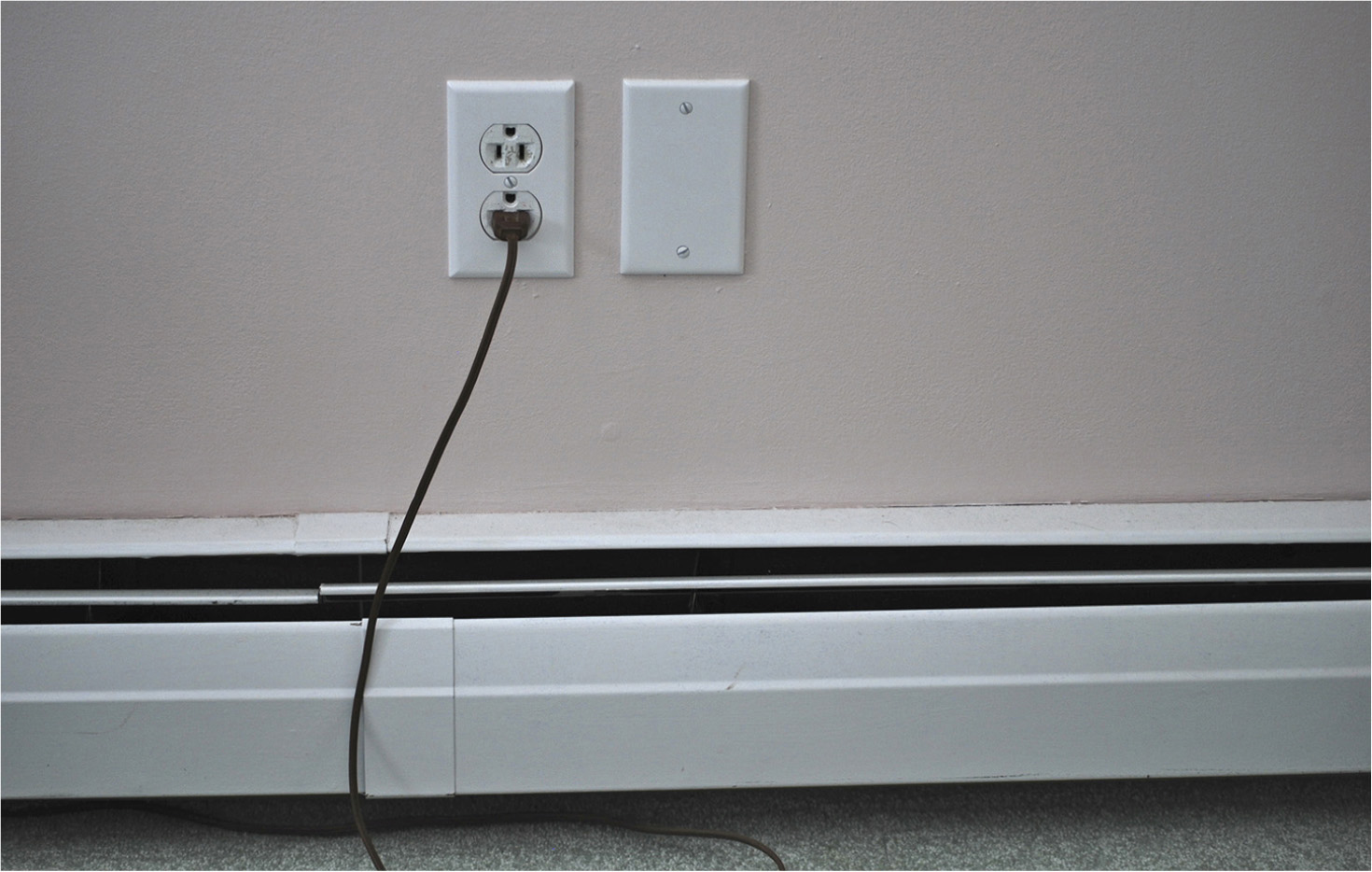
FIGURE 5-12 An electric baseboard space heater. The receptacle placed above it is a common listing violation because the cord is likely to enter the enclosure and be damaged by the heat.
Electric baseboard heat is available in various sizes, the electrical rating corresponding to the lineal length. These units may be obtained in low- and high-density models. The low-density electric baseboard heat equipment operates at a lower temperature, but the tradeoff is that for a given wattage, there is greater length.
If electric baseboard heat is to be installed, it is necessary to start with a design. Some utilities provide assistance. An engineer will visit the site and perform a heat-loss survey. This involves taking into consideration the area in square feet of the addition or complete building; its shape; the thickness of the walls, ceilings, and floors and the amount of insulation; the type of foundation; the number, type, and total area of windows; and above all, the climate, with the lowest expected ambient temperature.
The heat-loss survey will provide the information needed to determine the total amount of electric heat needed in watts. From this figure and the wall lineage, not including doors and any floor-to-ceiling glass, it is possible to determine size and placement of the strips. Electric baseboard heating units normally are centered under windows so that the rising heat will minimize moisture and ice.
An important consideration in planning an electric baseboard heat installation is that receptacles are not to be installed above the units, a very common violation. The reason for this is that power cords and extension cords plugged into a receptacle that is located above a baseboard strip could find their way into a heating enclosure and be damaged by the heat. Because receptacles must be placed at prescribed intervals, there is the potential for conflict. So receptacle and heat-strip placements have to be coordinated. For a problem installation, baseboard heating units are available that incorporate a built-in receptacle at the midpoint. When wiring them, connect the receptacles to the appropriate branch circuits, as opposed to bugging them off individual legs of the 240-volt heating circuits.
A baseboard heating unit includes the electrical wiring enclosure, so in roughing in the wiring, it is not necessary to install a wall box. Just leave a 10-inch whip emerging from a hole in the wall material. This hole should be located at the end of the electric baseboard strip, lining up with the wiring compartment. The hole will be concealed behind the unit, so your electrical work will be invisible.
Romex 12-2, shown in Figure 5-13, is used in a residence for most baseboard heating applications. Units can be daisy-chained to take advantage of the full ampacity, but don’t forget that this type of load is considered continuous, so it has to be multiplied by 1.25.

FIGURE 5-13 Romex cable is used extensively in residential wiring.
The total heat load is divided into zones. If the addition is a small room, there will be a single zone. A full house may have any number of zones, limited only by the capacity of the entrance panel.
Each zone has its own thermostat. The simplest type of thermostat circuit is in-line—two wires from the entrance panel or load center in and two wires out to the first baseboard heater. Thermostat input terminals are marked “line,” and output terminals are marked “load.” There is no need to match up the legs, and of course, there is no neutral.
The two conductors are connected at the breaker box to a 20-ampere double-pole overcurrent device. If Romex is used, the white must be reidentified using any color except white or green. This must be done at the breaker, thermostat, and baseboard heater.
An in-line thermostat has the disadvantage that the entire current drawn by the load must pass through the thermostat, and it must be switched by it. This means that the in-line thermostat will have a finite life, and the end-of-life event may be a terminal failure, accompanied by heat. For this reason, it is important to provide a metal wall box for the thermostat. The alternative is to have the in-line thermostat be a low-voltage device, as shown in Figure 5-14.
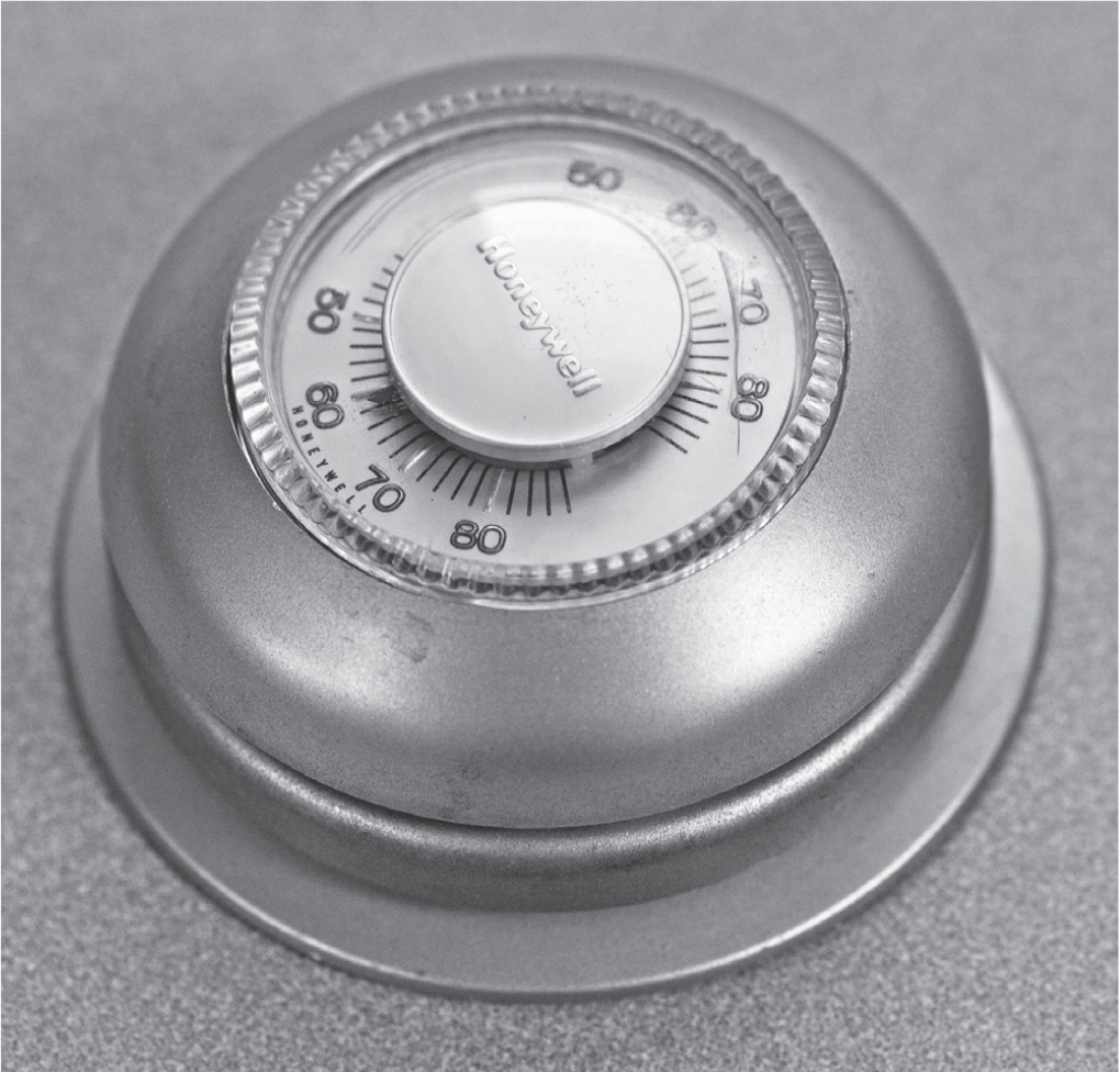
FIGURE 5-14 A thermostat should be installed at eye level. A standard wall box can be used.
The thermostat should be suitably located so that the temperature will be representative of the zone. The thermostat should not be on a wall where direct sunlight will cause it to turn off the heat, and it should not be in a drafty location by an exterior door. For the low-voltage control circuit, a transformer is required, as shown in Figure 5-15.

FIGURE 5-15 The control-circuit transformer is located at the furnace.
NEC Article 430, “Motors, Motor Circuits, and Controllers”
Everyone has noticed that once in a while, when a heavy load is switched on, the lights in the house dim for a second or so. If this is excessive, taking place when even modest loads are turned on, it can be a sign that the service or branch circuit is undersized. It is a consequence of Ohm’s law. When the amperes increase and there is resistance in a circuit, the voltage measured downstream from the resistance drops. This causes the lights to dim.
It is also a consequence of the fact that most loads draw more current when first powered up. This is true of simple resistive loads such as incandescent lighting and heating elements, but it is even more true of motors. Due to inertia of rest, it takes a while for the rotor to get up to speed, and during this time, the windings produce heat rather than the full-rated revolutions per minute. The same thing happens when the motor’s shaft is, for any reason, locked up and unable to turn. A motor with a locked rotor will quickly overheat unless it incorporates high-impedance windings. Step motors are like this, capable of high holding torque while not turning.
In the home, most motors are cord-and-plug connected. For the home crafter-electrician, wiring most motors is no more intricate than plugging them into a receptacle that is on a 15- or 20-ampere branch circuit. But there may come a time when you need to wire a large motor in an attached shop or garage, let’s say for an air compressor or a 12-inch wood planer. There will be a bit of a learning curve. If you proceed with the installation as you would for a comparable nonmotor load, there is a high probability that the overcurrent device will trip out within 2 or 3 seconds before the motor gets up to speed.
Motor Fundamentals
NEC Article 430, “Motors, Motor Circuits, and Controllers,” provides guidance. If you understand the rules for various sizes and types of motors, and if you apply them accurately, the installation will perform well. (That is, unless the motor is an old junker with worn-out bearings or winding insulation that permits excessive current leakage to ground.)
By way of background, we’ll review the primary types of motors, along with the basic principles that are common to all of them and make them work. A motor is a device that converts electrical energy into useful mechanical motion. By this definition, a loud speaker is a motor, but we are usually thinking of a rotary machine with one or two output shafts. These may be attached to pulleys, gears, saw blades, grinding wheels, hydraulic pumps, or many other types of devices that perform work for us.
Rotary electric motors consist of stators and rotors. The stator windings are mounted to the inside of the case. At both ends of this housing are bearings. The outer part of each bearing is held firmly in place so that it cannot slip or vibrate, and the inner parts of the two bearings, along with the shafts, are free to turn. One or both shafts extend through the bearing(s) and emerge through the end housings into the outer world.
The magnetic interaction of rotor and stator is what makes the shaft turn. The polarity of the magnetic field of either the rotor or the stator has to be reversed continually in order for the motor to turn. One but not both of these magnetic fields may be created by a permanent magnet. From time to time, a scheme will surface whereby both rotor and stator consist of permanent magnets, and perpetual motion is achieved with no external electrical supply required. This can’t happen. The polarity of either the stator or the rotor must be reversed periodically for rotation to take place. The only way to obtain this reversal would be for one set of permanent magnets to be physically flipped over, and this process would require whatever energy could be extracted from the output shaft. At best, the motor would rotate one-half turn and then stop, never to move again.
The spinning of the shaft of a rotary electric motor is made possible by a continuous input of electrical energy. Either the rotor or the stator must consist of electromagnetic windings that create a magnetic flux in a core, usually soft iron, that is magnetically permeable. A magnetic field is established with regularly reversing polarity because of the pulsating electricity supplied to the windings.
Consequently, the magnetic field of the rotor is continuously chasing after the magnetic field of the stator, causing the rotor to turn. To make the magnetic field reverse polarity, the electric current must reverse polarity, and this happens by a process known as commutation. The commutation can be internal (inside the housing of the motor, made possible by a commutator) or outside the motor, in which case the pulsations are the work of the utility-supplied alternating-current (ac) line voltage or are created by a local electronic oscillator or mechanical vibrator that is associated with the motor but outside the unit.
There are several types of motors, and what makes them differ is the commutation strategy and how it plays out in the rotor-stator interaction. The simplest type of rotary motor is the internally commutated direct-current (dc) motor. This was the first type of motor to be developed in part because prior to the Tesla-Westinghouse implementation of alternating current, only dc was available. The source was very inefficient short-lived chemical batteries, and for this reason, the first dc motors were not very powerful. Because they could not do much useful work, they were good only as amusing toys and scientific curiosities. With Thomas Edison’s early dynamo-powered electrical distribution system, dc motors suddenly gained great importance in the industrial world. With the arrival on the scene of the ac induction motor, the dc motor has lost ground but still occupies an important place in niche applications.
What Makes a DC Motor Turn?
In a dc motor, a nonpulsating voltage is applied to the terminals of the motor. The dc is applied to the stator windings, and a stationary magnetic field is established. The dc is also applied to the rotor windings. For this type of motor, rotor and stator windings are wired in parallel, and a variable resistance is put in series with the field windings to control the speed. The whole thing is easy to check out with an ohmmeter. Expect to see low resistance even with the variable resistance at its highest setting. If you can disconnect one pole of the variable resistance, each of the components can be measured individually.
Voltage has to be applied to the spinning rotor. If the wires are connected directly, they very quickly twist and break-off. This is the dilemma with any motor—how to get electrical energy into the rotor or otherwise make it magnetically active. In the dc motor’s most basic form, the input for the armature is applied by direct electrical connection to the brushes. These were originally actual copper brushes positioned so as to contact the different segments of the commutator, causing the current to flow in the correct sequence and polarity to the rotor windings.
Metal brushes have been replaced by carbon brushes, which have the advantage that they exhibit less sparking. They point straight toward the center of the commutator. The end of the brush is manufactured with a curvature that is compatible with the commutator. At the other end of the brush, inside the brush holder, is a light spring that maintains just the right pressure of the brush on the spinning commutator, advancing the brush a slight amount to compensate for wear.
These carbon brushes wear down eventually and must be replaced. If the motor has been running and has not overheated but refuses to start, the first thing to look for after a bad electrical connection has been ruled out is the brushes. If one or both appear to be too short, broken, pitted, or crumbly, both should be replaced. This usually can be done quite easily with no disassembly of the motor.
Exposure to moisture or oil from outside contamination or excessive bearing lubrication will soften the brushes and cause premature wear. If the brushes look good, sometimes the springs have lost their tension, and operation can be restored by stretching them.
Replacement brushes are readily available for most motors. Some technicians have made a hard-to-find brush by cutting down a larger one, but don’t forget, the curvature has to match that of the commutator. Also, small amounts of metal are added to the brush material, and it is heat treated in various ways during manufacture, so the electrical characteristics may not be suitable for the motor.
If the motor is not an enclosed type, it may be possible to see the brushes in action while the motor is running. A slight amount of sparking is normal, but when it becomes excessive, the brushes are worn and should be replaced. It is false economy to run the brushes to failure because commutator damage will result. As sparking increases, there is more heat, and this spells trouble. Before long, the sparking will resemble a bright gas flame, and the commutator will need to be rebuilt or replaced. This involves complete motor disassembly unless it is possible to clean the commutator in place.
If the commutator is badly pitted, the area where the brushes make contact is worn excessively, or if the commutator is out of round, as measured by a micrometer, it will need to be taken to a machine shop or motor rebuilder to be turned on a lathe. Afterward, the insulating material in the gaps between the commutator segments is cut back a slight amount using a tool that resembles a hacksaw blade with a handle. If this is not done, the motor will “eat” brushes. Worn brushes cause commutator wear, and a worn commutator causes premature brush failure. Changing brushes is a simple routine task, whereas rebuilding a commutator is a more extensive project.
Motors that have brushes require periodic inspection and maintenance. Some motors, numerically the vast majority, do not have brushes, and they require much less maintenance.
An Answer
The brushless dc motor solves this problem by having a rotor equipped with permanent magnets rather than electromagnetic windings. With no electrical connection to the rotor, there are no brushes. Commutation is external. A pulsed voltage of alternating polarities is applied to the field windings. It is created in a local electronic module that is associated with the motor but outside it. Because there are no moving parts except for the spinning rotor, maintenance is minimal.
Dc motors are plentiful in the home. Battery-operated children’s toys, computer disk drives, DVDs, inkjet printers, and automobiles all have dc motors. Some can be rebuilt; others have housings that are not intended to be opened. This shouldn’t stop you if you have an inquiring mind.
Steppers and Servos
Stepper motors and servomotors are interesting variants of the basic dc motor described earlier. Both are able to rotate a part turn and then stop with or without holding torque. They are both externally commutated. But the stepper motor is open loop, whereas the servo is closed loop, making for a higher-performance machine.
If, for any reason, the stepper motor falls out of synch, it must be reset. For this reason, it is not suitable in demanding applications. The servo system, in contrast, is equipped with an optical or other sensor attached to the motor or load so that there is continuous feedback. If the motor loses synchronization, there is ongoing error correction.
The stepper motor is externally commutated. Electrical pulses from outside go to the field windings, and the armature, as in other types of motors, chases after the rotating magnetic field that is created. A simple type of stepper is the variable-reluctance motor. It has a soft-iron notched rim that is attached to the outside of the armature. The notched teeth rotate with the armature close to the stationary field windings, separated by a small air gap. These teeth are alternately closer and farther from the stationary field windings. A freely moving body of high magnetic permeability such as soft iron always wants to move so as to create a magnetic flux path with the least reluctance. Reluctance in a magnetic circuit corresponds to resistance in an electrical circuit. Where there is magnetic flux, there is always a circuit. Sometimes, as in a stationary permanent magnet, the circuit is open.
Soft iron is quite permeable to magnetic flux, so there is less reluctance when the protruding parts of the armature pass through the flux lines coming from the stator. The armature will continue to position itself for minimum reluctance in the magnetic circuit. The magnetic field has to turn if step-motor rotation is to occur. For this to take place, the field coils must be energized by varying electrical pulses. An external controller is needed to generate these pulses. There should be two wires for each coil, but usually one side of each coil is connected inside the motor to a common wire.
Step motors have many wires, whereas standard brushed dc motors have two wires. A single pulse will make the motor turn a part turn. Then it will remain stationary with or without holding torque, which can be achieved by dc from the controller. The motor can endure this locked-rotor operation because it has more impedance than other similar-sized motors. Successive part rotations with pauses and reversals can occur in rapid succession as specified by controller programming. Ink-jet printers work in this way, and such behavior is useful in student robotics projects.
A waveform from the controller will cause the step motor to turn at the desired speed, reversing or making fractional turns. It would be possible, using a microphone and appropriate circuitry, to play notes on a musical instrument, causing the step motor to turn at different speeds.
Step motors may be manufactured with various numbers of field coils and notched teeth around the perimeter of the armature. These numbers work together to determine the smallest possible step, often expressed in degrees. For example, a 3.6-degree stepper has a maximum of 100 possible steps. This is also known as the resolution of the step motor.
Besides the variable-reluctance model, there are three other types of step motors—permanent magnet, hybrid, and Lavet. Permanent-magnet step motors do not have notched teeth. In their place are rotors with permanent magnets attached. They are characterized by greater dynamic and holding torque, so they would be the logical choice if a heavy load is to be moved or held in place. Hybrid steppers are small and powerful. This combination is made possible by the fact that they combine variable-reluctance and permanent-magnet constructions. The Lavet-type stepping motor turns only in one direction because it is single phase. This type of motor is suitable for wristwatches with quartz clocks because the motor requires little power, making for long battery life. Lavet steppers are also used for automotive dashboard instrumentation. The more robust servomotor, shown in Figure 5-16, is suitable for more demanding applications, such as automotive assembly-line machines connected to programmable logic controllers (PLCs).
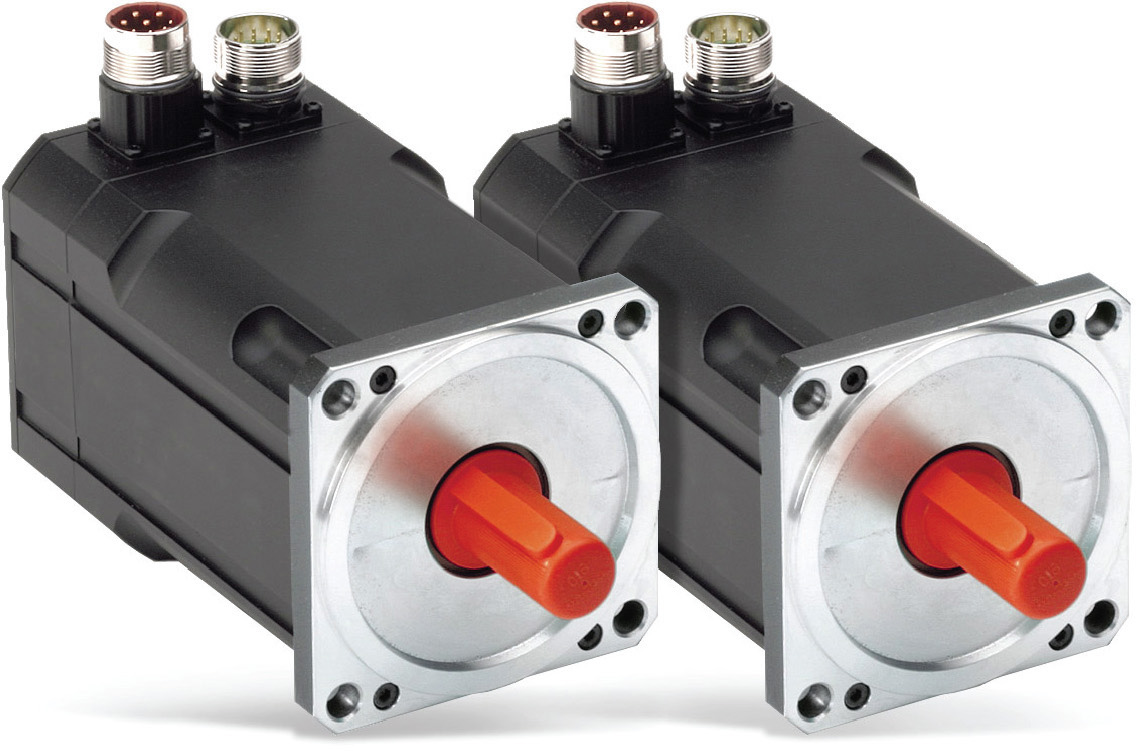
FIGURE 5-16 The servomotor is precise and robust with continuous feedback. It is used in many home automation projects. (Photo courtesy of Mouser Electronics.)
Step motors and servos often can be used interchangeably. In small, low-powered applications or where cost is the primary issue, step motors prevail. The servomotor moves in where reliability and robust performance are important and where the higher cost is not prohibitive.
The step motor works well until, due to load binding, electrical fault, or other problems, synchronization is lost. Once this happens, the error will not go away. Damage can be immense. Following this sort of event, it is necessary to stop the operation and resynchronize the controller and step motor.
The servomotor incorporates a closed-loop control system. The step motor–controller combination is open loop. For the servomotor’s closed-loop operation to work, a sensor is required. It should be located, if possible, at the load rather than at the motor in case the fault takes place between them. The servomotor control senses the position and speed of the motor or load. When an error is detected, the controller sends appropriate command data to the motor, and the system returns to normal.
Servomotors are not specific motor types, but they are characterized by the fact that there is a motor sensor-controller combination. The control is always closed loop. Most servomotors are capable of rotating 120 to 180 degrees. A continuous servomotor is able to turn 360 degrees in either direction. Any one of them is appropriate for robotic assembly-line production. Often a single robot will have several motors. There are numerous other applications, such as solar array tracking and the clock drive for an astronomical telescope, allowing it to remain pointed at a celestial object for long hours needed for time-exposure photographs. With a USB connection to a computer, these instruments can instantly find numerous deep-sky objects.
When we talk about ac motors, it is generally understood that we are referring to synchronous or asynchronous (induction) motors, both of which require an external ac power source. Thomas Edison envisioned a strictly dc electrical generating and distribution system. Beginning in lower Manhattan but quickly spreading far and wide, his system was an outstanding achievement and a tribute to his meticulous attention to detail and ability to think big. But George Westinghouse and Nikola Tesla saw the possibilities for a radically different electrical system that within a few years brought a new kind of electrical power into factories, businesses, and homes worldwide.
Dc power flows from the source to the load when a steady voltage causes current to flow through the circuit. At the source, there are two terminals, one positive and the other negative. If conductors are connected to these terminals and to a load, terminals at the load also will be positive and negative.
Electrons are negative and flow from the negative to the positive pole of a source such as a battery or dc generator. This is strictly a matter of semantics, however, and derives from the fact that originally it was thought that current flowed from positive to negative. Protons and neutrons attract one another because they have opposite charges, but there is nothing intrinsically positive about a proton and negative about an electron. It is just the way we designate them for historical reasons.
Ac also involves the motion of electrons. The difference is that the two poles reverse polarity either 100 or 120 times per second depending on the country. Two reversals constitute a cycle, so the most common frequencies are 50 and 60 Hz.
Ac does not switch abruptly. Square-wave power of that sort would have several disadvantages. The fast rise and fall times would make for powerful and harmful harmonics. Ac as supplied by utilities throughout the world consists of a pure sine wave, which is a consequence of the rotary nature of the generator. Figures 5-17 through 5-19 show sine-wave, square-wave, and triangular-wave graphic representations.
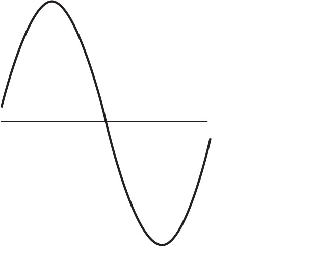
FIGURE 5-17 Sine wave.

FIGURE 5-18 Square wave.
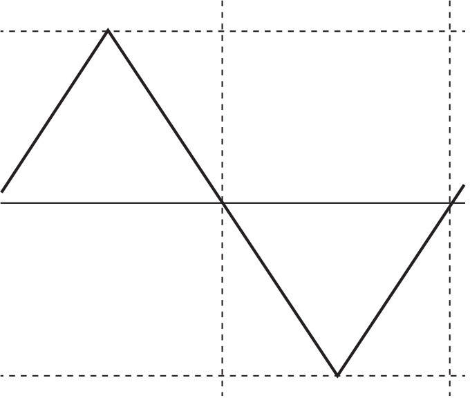
FIGURE 5-19 Triangular wave.
The voltage produced by a rotary generator, if plotted on a graph where the vertical axis represents electromotive force in volts and the horizontal axis represents time in seconds, conforms to a sine wave. There are several points worth mentioning: the peak-to-peak voltage is higher than the nominal line voltage, as specified by the utility and required to run electrical equipment. What we are concerned with is the root-mean-square (RMS) value.
Looking at the sine waveform, notice that the rate of change is not the same at all times, as it would be in a triangular waveform. In a sine wave, the rate of change is greatest when the voltage is least, and the rate of change is least when the voltage is greatest. This fact is of great importance to electronics technicians, for whom capacitive and inductive loads are objects of intense interest. This is so because the impedance of these loads depends on the rate of change, not the actual value, of the applied voltage. In a capacitor, the greatest amount of current flows when the voltage is least, crossing the zero line.
For a purely capacitive or purely inductive load, the applied voltage and measured current are 90 degrees out of phase. In an inductive circuit, the current lags behind the voltage, whereas in a capacitive circuit, the current leads the voltage. In a resistive circuit, the waveforms of the applied voltage and measured current coincide and are said to be in phase.
Why It Is Important
All of this is of limited interest to the home crafter-electrician when wiring switches and receptacles in an addition or new building, but it is good to understand what is going on for the perspective that it provides. Moreover, as discussed later in this book, when it comes to data networking projects such as Ethernet circuits, a bit of background knowledge will enhance your ability to design, install, troubleshoot, and repair such systems.
How is this relevant to motors? The introduction of ac made possible some new types of motors—synchronous and asynchronous (induction) and both of these in single- and three-phase versions. Ac motors had some advantages, but for many decades, the dc motor could not be matched when it came to easy reversibility and smooth speed control. Since the mid-twentieth century, with introduction of the variable-frequency drive (VFD), ac motors have become competitive, if not altogether dominant, in these areas as well.
One of the advantages of ac is that the utility-supplied power can provide external commutation so that switching is obtained without effort. In effect, the shaft of the utility’s generator becomes the commutator for the motor.
The speed of a synchronous motor is exactly in step with an integral multiple of the utility line frequency. The multiplier is equal to the number of poles in the rotor. There are several configurations. Expect to see electromagnetic windings built into the stator. The line current is fed to these windings, and the magnetic field of the stator rotates in accord with the line-current pulses, and the rotor turns at that speed.
Synchronous motors come in many sizes, conforming to the intended use. Small synchronous motors are used as timers and clocks. The speed depends exactly on the line frequency, so they are very accurate. Utilities watch their frequency carefully, and if they detect an error, they temporarily increase or decrease the speed of the generator so as to get back on track.
Small synchronous motors will start on their own, so they are said to be self-exciting. Large synchronous motors have too much inertia at rest to be self-starting. An auxiliary induction motor (pony motor) is needed to get them going, or induction windings may be built right into the motor.
A large synchronous motor is very expensive to manufacture, but it is used in special applications where accurate synchronization to the line frequency is desired. Additionally, large synchronous motors are highly efficient, cheaper to run, and provide power correction in facilities where there is heavy inductive loading. Troubleshooting a synchronous motor is similar to troubleshooting a dc motor. After verifying that the supply voltage is present at the motor terminals, ring it out with an ohmmeter. Resistance between any (and all) windings and ground should be in the high-megaohm range, and resistance of each winding should be low but not zero.
A Great Invention
Most ac motors in operation throughout the world today are single- and three-phase induction motors. They are relatively inexpensive to manufacture and, without brushes, for the most part maintenance-free. The small single-phase induction motor, as found in many stationary home tools and appliances, has sealed bearings. Because lubrication and brush maintenance are not required, the motor generally runs the life of the appliance with no maintenance or attention of any kind.
The induction motor was invented independently by Galileo Ferraris and Nikola Tesla in the 1880s, and working models were marketed first by Westinghouse and then by General Electric, eventually populating factory, farm, and home wherever electrical distribution lines permitted. As in synchronous motors, utility-supplied ac is connected to the induction motor’s stator, producing a rotating magnetic field. What is radically different is the way in which the energy gets into the spinning rotor. Stator and rotor are, in effect, the primary and secondary of a transformer. The rotor is energized by magnetic induction, with no direct wiring. Then, as in other electric motors, the rotor’s magnetic field chases the stator’s magnetic field, and this is what makes the shaft turn.
Nevertheless, an induction motor is not synchronous. The rotor’s spin depends on the ac line frequency, but spin and line frequency are not locked in synch. The rotor’s spin is slower than the rotation of the stator’s magnetic field by a certain amount, typically 10 percent. It is not merely out of phase like voltage and current waveforms when there is a reactive load. The rotor turns more slowly than the stator’s magnetic field by an amount determined by the load and the torque of the motor. This amount is called slip, and it is always relevant to an induction motor. If the rotor’s and stator’s magnetic fields were, hypothetically, to turn at the same speed, there would be no inductive coupling and no reason for the rotor to rotate. Slip therefore is a necessary part of the induction-motor picture. It should not be regarded as some sort of wasted energy. Tesla, and later Charles Proteus Steinmetz at General Electric figured all this out and quantified it.
Tesla also conceived of three-phase power. It is more efficient to generate, distribute, and use than single-phase power once the infrastructure is in place. The waveform is shown in Figure 5-20. (There is also a two-phase system, but it is rarely used.)

FIGURE 5-20 Three-phase waveform.
Most single-family dwellings have single-phase services, but if the size of the load requires a 400-amp or greater service, it probably will be three phase. An ordinary Delco-Remy automotive alternator generates three-phase power, which is converted to dc in a diode network that is inside the alternator.
The home crafter-electrician may never have occasion to wire a three-phase load, but you should know what is involved. Many individuals have acquired perfectly viable high-quality woodworking or other equipment for the home or shop, only to find that the item cannot be powered by the single-phase system without resorting to conversion strategies.
Actually, once you know the basics, three-phase wiring is easier than single-phase wiring. This is so because for a given size load, the conductors are smaller. In large-horsepower applications, this is critical.
A good way to get a feel for three-phase circuits is to travel the roads, looking at power lines, transformer arrays, and services. Have someone else drive, lest you become so intent on the circuitry that you drive into a power pole, knocking out the very system that you intended only to observe.
Large high-voltage transmission lines, unless they are dc, are always three phase. The three-phase conductors are invariably at the top. They may consist of three pairs. The two conductors that make up a pair can be close together. If by mishap they contact each other, it is not catastrophic because they are at the same potential. They are connected in parallel so as to permit the use of smaller and more manageable wires.
Experienced utility workers can tell at a glance the rated voltage of a line, judging by the height of the tower and construction of the insulators. If you follow the high-voltage power line, you will see that it terminates at a substation.
Large restaurants, hotels, and grocery stores with lots of refrigeration, as well as good-sized office buildings and most factories, have three-phase services. The ones that are aerial are easy to distinguish from single-phase services because they have three conductors (not counting the grounded neutral) or six if they have been paralleled.
A three-phase meter socket has three input and three output lugs, possibly twin lugs to accommodate paralleled conductors. The service-entrance conductors usually disappear into the building. Inside, they go into a three-phase entrance panel unless there is a main disconnect in a separate enclosure.
The three-phase entrance panel superficially resembles a single-phase entrance panel, but they are not the same. A three-phase entrance panel has a three-phase main breaker, shown in Figure 5-21 (or three separate cartridge fuses). The main breaker has three input lugs, and it energizes three vertical bus bars that run down almost to the bottom of the box, with a space below them so that wiring can cross over.
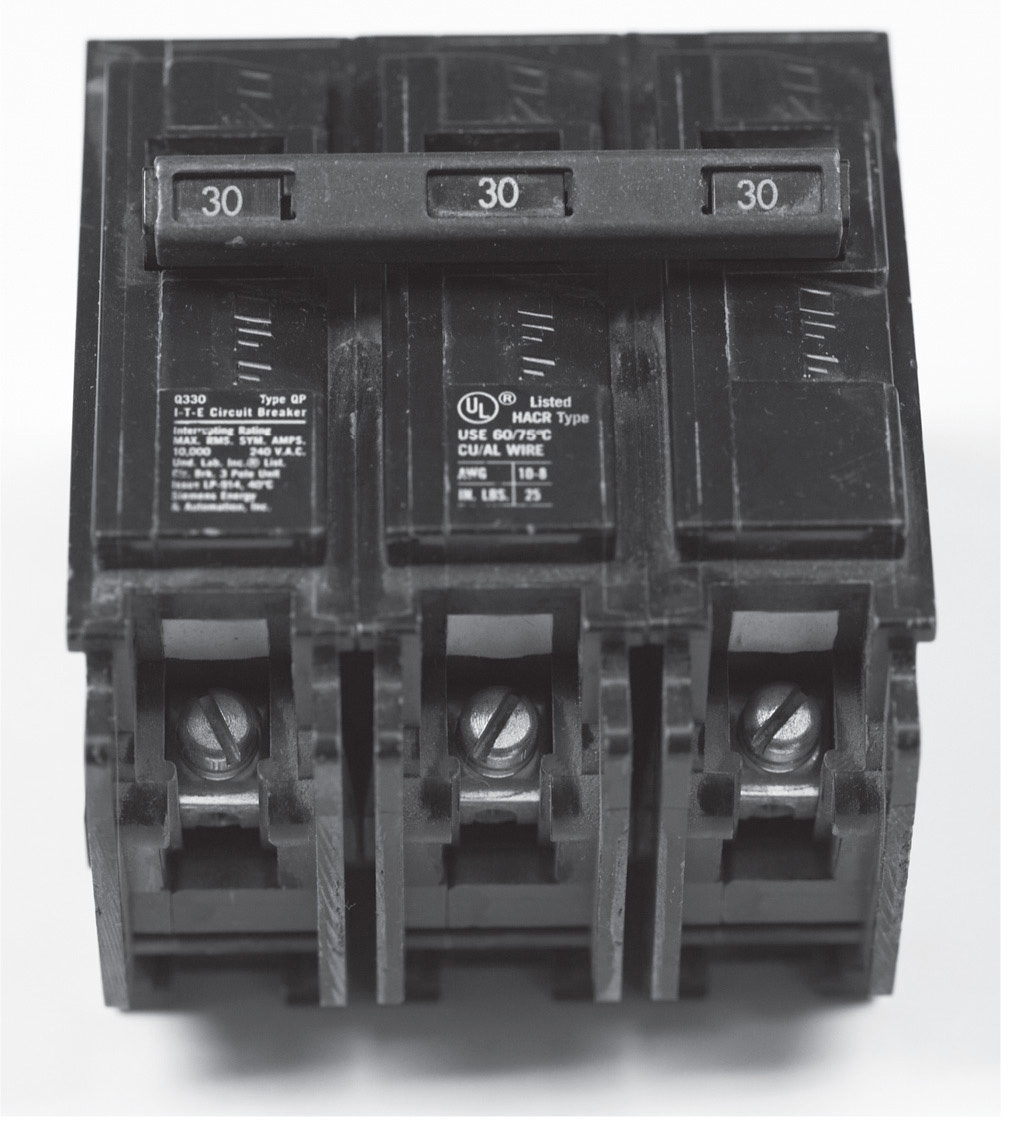
FIGURE 5-21 A three-phase circuit breaker, suitable for supplying power to a small three-phase induction motor or similar load.
The main breaker has a single handle, permitting the three bus bars and all loads to be powered down simultaneously or, in the unlikely event that the main trips out, ensuring that all three open together. This type of panel will accept single-, double-, or triple-pole breakers for branch circuits and feeders. Thus three-phase loads or single-phase pole-to-pole or pole-to-ground loads may be connected.
A three-phase motor is powered through a three-pole breaker of appropriate ampere rating. Unless there is auxiliary equipment, the neutral is not required. Run the three hot legs and, of course, the equipment-grounding conductor in the same conduit or cable first to the motor controller and from there to the motor.
One of the interesting things about a three-phase motor is that the direction of rotation can be reversed simply by reversing the connections of any two of the three wires. This may be done at the output of the three-pole branch-circuit breaker in the entrance panel or load center, at the input or output at the motor controller, at the motor terminals, or at any junction box as long as other loads will not be adversely affected. Choose the location that is most accessible. To facilitate this operation, sufficient wire slack should be left in the initial installation.
The wiring for correct rotation may be determined by trial and error for some types of equipment, but care must be taken. Some types of pumps, if rotated in the wrong direction, are damaged to the extent that the seals must be replaced, involving a teardown. Also, a hazardous situation could be created. If there is a reversing switch, it will not matter how the rotation is established at the outset, provided that the switch is not labeled. A circular saw or a fan can be wired by trial and error, visually observing the rotation. A three-phase motor rotation meter, shown in Figure 5-22, is helpful in getting the rotation right.
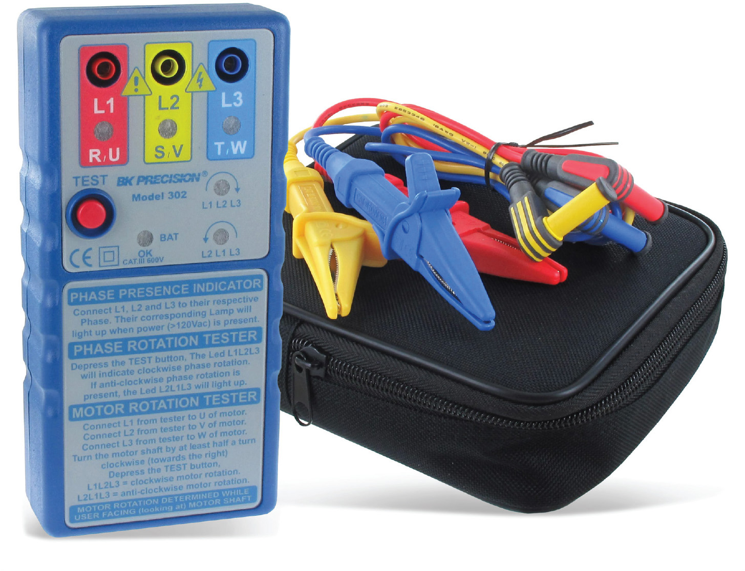
FIGURE 5-22 A three-phase motor rotation meter. (Photo courtesy of Mouser Electronics.)
Some pumps and blowers will push the liquid or gas in the correct direction regardless of direction of rotation, but the output will be greater one way than the other. This is so because the impeller blades are cupped, and they push more volume when the concave surface is leading. This is noticeably true for a three-phase submersible deep-well water pump. You can time how long it takes to fill a 5-gallon pail from a faucet, reversing connections at the control box or wellhead to find the best output.
Another consideration arises when wiring a three-phase motor. For maximum motor life and economy of operation, the three phases should be balanced. It is possible, especially in an older motor, that the windings have not retained their original impedances. Similarly, the line voltages for the three phases may differ by a slight amount. The idea is to match loads to lines in such a way that the errors cancel out rather than reinforce one another. The reconfiguration must be done so as to preserve correct motor rotation.
First, establish the desired motor rotation. Then, at a convenient splice location, label both line conductors and terminals A, B, and C. With the motor driving its load, use a clamp-on ammeter to measure the current in each leg. Write down the readings. Then roll the connections, joining A to B, B to C, and C to A. This operation will not change the direction of motor rotation. Again, write down the three readings. Finally, roll the connections one more time, joining A to C, B to A, and C to B. Again record the readings. Choose the set of connections that gives the most uniform readings. We have to realize that the utility line voltage may vary depending on loading. The utility makes every effort to balance the load, but no one can foresee the use that customers will make of their accounts at all times. You may have to revisit the three-phase current readings at different times of day and night and on different days of the week to get the total picture.
The Universal Motor: Small, Inexpensive, Ubiquitous
Another type of motor that is very common in the home and shop is the universal motor, so called because it can run on dc or ac or at other frequencies within limits. The universal motor is small, lightweight, and its speed and direction of rotation may be changed, making it ideal for many applications, such as portable electric drills or sewing machine motors. It makes a distinctive loud whirring sound when running. The defining characteristic is that unlike other motors, the rotor and stator windings may be wired either in series or in parallel.
Universal motors are not used in continuous-duty applications, where the lifespan would be limited because of the high-speed commutator-brush combination. But the ease of control by means of internal speed and reverse switching and the high speed and torque relative to size and weight make them ideal for hair dryers, electric drills, food mixers, and many other applications in the home and shop. Brushes are easy to change, and this may have to be done two or three times in the life of the motor. Because many of these tools and portable appliances are moved around a lot while in use, a frequent cause of failure is the power cord, which can be replaced if you can save the old strain relief or fabricate a new one.
Following this brief survey of the types of motors that you may find occasion to rewire or repair in the home or shop, we’ll return to NEC Article 430. The object is to learn how to size the overcurrent device(s) and branch-circuit conductors in such a way that the motor will be able to start and run while driving the load and yet a hazardous situation will not be created.
The NEC deals with this high startup demand in a way that is unique to motors. There are a lot of variations depending on the size and type of motor, but in most applications, the bottom line is that you do not size the circuit according to the full-load current on the nameplate. Instead, you take the horsepower off the nameplate and refer to the appropriate table at the end of Article 430. This table gives a different full-load current. The circuit is sized accordingly. Other tables in Article 430 permit choosing a much larger branch-circuit overcurrent device than would normally correspond to the circuit size. The key concept, and it may seem counterintuitive, is that this overcurrent device is intended to protect the branch-circuit conductors only from short-circuit and ground-fault events but not from overloads.
If the motor draws excessive current because of internal winding insulation breakdown, rotor lockup, or stalling due to the driven load, the circuit will be interrupted by a separate overload device that is in a motor controller adjacent to the motor or in the motor. This slow-acting overcurrent device will protect the motor and supply circuit in the event of overload but will not prevent the motor from starting up and attaining rated speed, whereupon the counter-electromotive force will limit the current.
Apprentice electricians for many years have struggled with this arrangement, fearing that the branch-circuit conductors will overheat and incinerate the building. But it is a fine-tuned, carefully engineered design that has proven safe and reliable when constructed according to the NEC mandates contained in Article 430. Any time you have occasion to wire a motor that is larger than a cord-and-plug–connected fractional-horsepower unit, it is time to go through Article 430 carefully and follow the requirements that pertain to your installation.
NEC Chapter 5: “Special Occupancies”
Chapter 5 opens with extensive coverage of hazardous conditions, most of which is not relevant to the home crafter-electrician, with some important exceptions that we shall note. Special designs and installation techniques are necessary in hazardous locations, places where there are or may at times be accumulations of explosive or flammable gases, volatile liquids, dusts, or larger fibers that can become airborne. These locations are identified and delineated as three separate classes depending on the flammable material. Each class is divided into two divisions corresponding to the immediacy of the hazard. So there are six types of locations, Class I, Division 1 being the most hazardous and Class III, Division 2 being the least hazardous. Areas that are not hazardous, such as most residential locations, are termed unclassified. The six classified locations require different types of wiring and electrical equipment that are approved for the location, such as that shown in Figure 5-23.
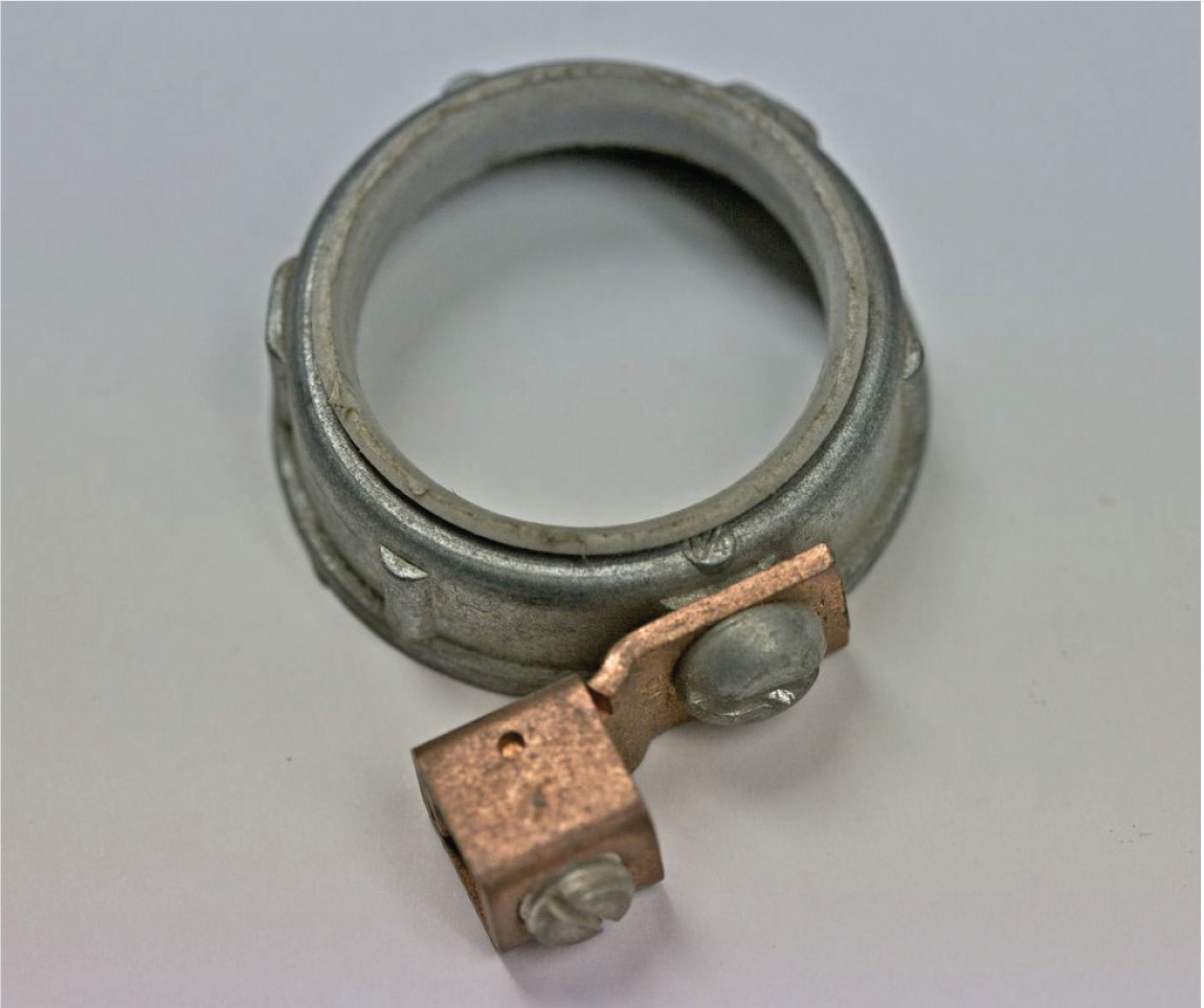
FIGURE 5-23 Classified locations require specialized materials and wiring methods.
NEC Chapter 5 also covers other special locations that, while not hazardous in the sense of the classified locations mentioned earlier, are sensitive in varying degrees and require wiring methods and materials that go beyond the ordinary Romex installation that is seen in a low-rise single-family home. The home crafter-electrician must be sophisticated and vigilant regarding any of these issues that may arise. Here are some of the articles that cover special locations that may be relevant to a home wiring project:
• Article 511, “Commercial Garages, Repair and Storage”
• Article 514, “Motor Fuel Dispensing Facilities”
• Article 516, “Spray Application, Dipping, Coating, and Printing Processes Using Flammable Combustible Materials”
• Article 550, “Mobile Homes, Manufactured Homes, and Mobile Home Parks”
• Article 590, “Temporary Installations”
You may wonder what Article 511, “Commercial Garages,” has to do with a home wiring project. A good proportion of residential properties include a garage that is attached to or detached from the primary house. If the garage is attached, it must be wired and must conform to the NEC. If it is detached, power is optional, but if it is wired, it must comply. The garage can have its own service, or it can be powered via underground or aerial feeder from the house. How it is wired depends on whether the garage is deemed to be residential or commercial. A residential garage can be wired in Romex, and the wiring resembles ordinary house wiring with GFCI receptacles. If the garage is commercial, you’re looking at metal raceways.
A great many commercial garages are owner-built, and it is a common Code violation to see them wired in Romex with no thought of the hazards. There are gray areas. Often the garage is used by a backyard mechanic who works on automotive vehicles on a part-time basis. The garage may begin as a strictly residential parking garage, but as the teenager in the house grows older, it may become the site of extensive automotive repair and fabrication. The combination of heat systems, wet floors, welding equipment, grinders, battery chargers, and disassembled fuel systems opens the possibility for shock and fire hazards.
Many of these backyard facilities are as much or more prone to disaster than a full-scale commercial garage with a large payroll. Before designing and installing a wiring system for one of these buildings, a decision should be made as to whether it is to be considered residential or commercial. Not only the immediate usage but future activities need to be considered. The key concept is not at all whether the work is to be done for pay. It is based on the presence of vehicles or equipment that use flammable fuels (including propane or natural gas) and whether the fuel systems will be opened, allowing for fuel vapors to become a factor.
Do you have a gas pump on your property? Gasoline is a highly volatile liquid that under certain conditions releases explosive vapors. You don’t want to just throw together an electrically operated gas pump, as seen on many farm properties. Consult NEC Article 514 and observe all setbacks and wiring standards.
If you have a woodworking shop, parts of it may be Class II, Division 1 or 2. This depends on the volume of sawdust, how fine it is, whether a collection system is in place, how large and well ventilated the area is, and other factors. Finely divided sawdust can remain suspended in the air, and at a certain concentrations, it becomes a potential explosion or flash-fire hazard, awaiting an electrical arc from a switch, motor-controller relay, or brushes within a motor. Over a period of time, standard wall boxes can become packed with sawdust, preventing normal heat dissipation. Sawdust can settle on a motor enclosure, especially if there is an oily film. This will cause the motor to overheat, setting the stage for a smoldering fire that can take off after the shop is closed for the night.
Associated with a woodworking shop is sometimes spray-painting activity. This can involve a full-scale spray booth or merely an area where occasional airborne paint or solvent is present. Refer to NEC Article 516.
If you have a full-scale spray booth, an exhaust fan, lighting with a switch, and receptacles may be needed. Because airborne solvents and paints will be present at times, the area is classified. The safest and least-expensive way to deal with this is to keep all electrical wiring and equipment out of the area. The exhaust fan can be located under a shroud outside, high above grade. Lighting can be outside the spray booth, separated by glass.
If the building is a mobile home, it will be prewired during manufacture. Additions and alterations to mobile home wiring are notoriously difficult because the breaker box is recessed inside a finish wall, usually in a tight closet-like space that serves as a utility room. Wall finish is fastened to undersized studs by means of adhesive. The box will be small, and often there is no space for an additional circuit. Because everything inside is finished, it may be necessary to resort to surgical techniques. Also, because the raceway that brings the feeder into the box from under the mobile home is technically not part of the service, it is permissible to pull in an extra branch circuit, provided that the conduit fill limit is observed.
The home crafter-electrician or a local professional will have to build the service. Mobile homes are different from other buildings in this respect. An aerial service with meter is never attached to a mobile home. Instead, the service drop or lateral is brought to a separate pedestal at a distance from the mobile home that is specified by the utility. This pedestal contains the meter and the main disconnect. The conductors between the main disconnect and the mobile home constitute a feeder, with overcurrent protection at both ends. It is a two-leg 240-volt circuit with a neutral and equipment-grounding conductor, four wires in all. It is brought underground, usually in PVC conduit, if possible, to a location directly under the breaker box. The best procedure is to have this feeder in place before the mobile home is delivered to the site.
Temporary Installations
Most large electrical projects require some temporary wiring, just to provide power so that the main project can be done. Article 590 contains requirements for temporary installations. Some of these requirements are less stringent than for permanent work, but this is no license for a chaotic, low-quality product. Some workers maintain a very relaxed stance toward work-site wiring, a “get ‘er done” attitude predominating. Actually, great care should be taken to ensure that proper grounding, protection of conductors, proactive elimination of potential fire hazards, and other good procedures are observed. A very dangerous practice is sawing off extension-cord ground plugs because continuity of the equipment ground is a definite safety issue for prevention of hazardous voltage on normally non-current-carrying conductive materials. No one wants to carry the memory of a job-site fatality. To prevent this, compliant temporary wiring is the place to start.
Temporary wiring is permitted during a period of construction, remodeling, maintenance, repair, or demolition of buildings, structures, equipment, or similar activities. It is to be removed immediately on completion. It is permitted for up to 90 days for holiday decorative lighting. Except as specifically modified in Article 590, all other NEC requirements for permanent installations apply to temporary wiring installations.
Romex is permitted as temporary wiring in all locations. On construction sites, unlike in permanent wiring, enclosures are not required for wire-nut splices. Ground continuity of the equipment-grounding conductor must be maintained. GFCI protection is required for all temporary receptacles. Cord sets for portable use are permitted to meet this requirement.
Special Equipment
NEC Chapter 6, “Special Equipment,” contains a series of articles each of which focuses on a type of equipment that requires specialized wiring designs and installation techniques. Most of this equipment falls outside of the home crafter-electrician’s primary field of interest, but some of it may find its way into a residence, and we shall take note of it.
Article 620, “Elevators, Dumbwaiters, Escalators, Moving Walks, Platform Lifts, and Stairway Lifts,” is a highly technical article that covers this type of work. It is unusual for the home crafter-electrician to wire an elevator, much less a bank of elevators, in the ordinary low-rise residential occupancy. But it is a distinct possibility that a stairway chairlift may be installed in the home for the benefit of a disabled person when the bedroom is not on the first floor.
A stairway lift is purchased as a complete assembly with a rail that is sized to fit the existing stairway in the home, straight or curved. Along with the purchase, professional installation is available. A skilled homeowner certainly can do this work, including the electrical component. Full documentation that comes with the model should answer any question that arises.
NEC Article 625, “Electric Vehicle Charging Systems and Welders”
As hybrid and fully electric vehicles become more common, homes are being equipped with vehicle charging systems. Such a system can be connected to the utility service, a dedicated generator, fuel cells, or wind or solar power. These sources can be integrated with one another in various permutations for increased reliability and/or economy. The NEC devotes an article to equipment requirements, and as always, the focus is safety. To this end, there are mandates that pertain to the electric vehicle coupler, grounding, GFCI placement, ventilation, disconnecting means, and interactive systems. If you are setting up an electric vehicle charging system, consult Article 625 to make sure that you get all the details right.
Article 630, “Electric Welders,” provides guidance on wiring provisions for this type of equipment. It is increasingly finding its way into home workshops. If run through the home electrical service, it may be necessary to upgrade to 200 amperes. A common type of machine is the 225-ampere stick welder. The ampere figure refers to the low-voltage output, not the power supply required. Larger dc welders give superb performance and work well with many difficult metals. And then there are the smaller 120-volt shielded-arc wire-feed models, excellent for light to medium metal fabrication and repair.
If there is a unit on-off switch on the welder, and if it is cord-and-plug connected and within sight of the branch-circuit breaker, there is no need for a separate disconnect. The only task is determining the correct overcurrent device and branch-circuit conductor size.
Welders have a very forgiving duty cycle. Welding is typically a stop-and-go operation, with frequent breaks for chipping, grinding, and repositioning the work. Additionally, the waveform of the welder output current has an inherent duty cycle, which is marked on the welder. It differs for the various heats. (One of the heats, typically 75 amperes, indicated by a circle around the number, has a heavier winding and is used for thawing frozen underground metal pipes, which may require hours of continuous operation.)
Assuming that you are not doing a group installation, the ampacity of the supply conductors (not to be confused with the welding cable) is not to be less than the I1eff value on the rating plate attached to the welder. This includes the duty-cycle allowance. Alternatively, it is permissible to multiply the rated primary current by the multiplier given in NEC Table 630.11(A). Notice that these duty cycles run quite low, permitting small supply conductors.
Several 240-volt receptacles of the proper ampere rating can be daisy-chained around the garage or shop, permitting the welder to be operated at different locations. A receptacle should be placed near the door so that the welder can be positioned outdoors if needed. An outdoor receptacle on the exterior wall of the building is also a possibility.
A Big Wiring Project
NEC Article 680, “Swimming Pools, Fountains, and Similar Installations,” is not too many pages long, but it is densely written and contains some highly technical information. Around bodies of water, there is a high potential for shock. But the provisions in this article, if followed faithfully, will mitigate that hazard. What is needed is great attention to detail and careful workmanship.
The provisions of Article 680 apply to construction and installation of electrical wiring for and equipment in or adjacent to all swimming, wading, therapeutic, and decorative pools, fountains, hot tubs, spas, and hydromassage bathtubs, whether permanently installed or storable, and for metallic auxiliary equipment, such as pumps, filters, and similar equipment. The statement of scope is quite broad. Where there is electricity and water, whether human-made or natural, you’ve got some very technical and exacting work to do. Fortunately, it is all spelled out in Article 680, so it is just a question of going through this article until all the details of the installation are grasped.
It is beyond the scope of this book to cover all the details of the electrical part of a swimming pool installation. For now, we’ll indicate some of the main areas of concern. The good news for the home crafter-electrician is that you don’t have to become an expert in this broad subject until such time as you are called on to do such an installation. If this does happen, a wise choice would be to call in a professional electrician on a consultative basis. In the meantime, it is good to delve into the subject just to find out what is involved.
Naturally, there are all sorts of clearances. Service-drop conductors, communications, radio and television coaxial cables, network-powered broadband communications systems, and other overhead conductors that pass near the pool are required to maintain horizontal distances from the inside wall of the pool and water edge. This is in addition to ground clearances that are in effect even if there were no pool.
Underground wiring, depending on raceway type, must meet prescribed minimum cover requirements. Receptacles within 20 feet of the inside wall of a pool must be GFCI protected. Luminaires have required vertical clearances from the pool depending on whether they are indoors or outside. Switches are to be at least 5 feet horizontally from the inside walls of a pool unless separated by a solid fence, wall, or other permanent barrier.
All of this is straightforward. Where swimming pool wiring differs from other types of electrical wiring in the home is the whole subject of bonding, and this becomes complex and exacting. To comply with NEC requirements for swimming pool wiring, it is necessary to develop a detailed plan in advance because of the need for equipotential bonding. If the swimming pool consists in part of below-grade concrete, it will have to incorporate a rebar grid that is bonded to the electrical grounding system. This is also true of slablike construction that surrounds the perimeter of the pool.
If there is an electrical fault, steep voltage gradients can become established within the pool and in the area surrounding it. If a person, especially with bare feet, walks on the ground or occupies the pool and is positioned perpendicular to the voltage gradient, severe shock and electrocution are possibilities. To eliminate this voltage gradient, the NEC requires equipotential bonding. This has to be set up as part of the formwork before the concrete is poured.
The bonding is accomplished by using insulated or bare solid (not stranded) 8 AWG or larger conductors connected to all the following:
• Conductive pool shells
• Perimeter surfaces
• Metallic components
• Underwater lighting
• Electrical equipment
• Pool water
This 8 AWG bonding conductor need not be run all the way back to the service-entrance panel. It is only necessary for it to connect to the electrical grounding system. Under no circumstances should a separate floating-ground electrode be thought to suffice because this would be totally ineffective. Article 680 goes on to cover, as separate topics, spas and hot tubs and fountains. Here are important grounding, bonding, GFCI, and other requirements that must be met, so careful review of the article is essential before beginning the installation.
Article 682, “Natural and Artificially Made Bodies of Water,” deals with some of these same issues, such as the need for an equipotential plane and bonding.
Article 690, “Solar Photovoltaic Systems,” Article 692, “Fuel Cell Systems,” and Article 694, “Wind Electric Systems” include NEC requirements for these interesting and increasingly timely technologies. We’ll discuss details in Chapter 14.
These are the 2014 NEC articles that are most relevant to residential electrical installations. A home crafter-electrician who is serious about doing quality work that will be safe for family members, visitors, and future owners, will obtain this volume and adhere to its mandates.
Some Special Wiring Methods
It’s not all Romex! Many cable and raceway materials are suitable for various applications. Here’s a brief summary.
Rigid Metal Conduit
Rigid metal conduit (Type RMC) is the heaviest of the metallic raceways. It is similar to galvanized water pipe in that the threads are compatible. But water pipe must never be used in electrical work. The inside diameter is less and the inside surface is rougher, so conductors pull harder and may be damaged. RMC is suitable for the most demanding applications, and it may be used anywhere that raceway is permitted, including all home projects. For underground lines, it is useful where it is impossible to go deep due to bedrock. RMC is expensive and difficult to thread and bend, so it is rarely used where other raceways are permitted. RMC is to be secured within 3 feet of each outlet box, junction box, device box, cabinet, conduit body, or other conduit termination. RMC is to be supported at intervals not exceeding 10 feet.
Liquidtight Flexible Metal Conduit
Liquidtight flexible metal conduit (Type LFMC) is similar to FMC, but it has a liquidtight outer plastic covering. Securing and supporting requirements are the same as for FMC. LFMC is permitted as an equipment-grounding conductor. Its use is permitted outdoors, for direct burial, and embedded in concrete.
Liquidtight Flexible Nonmetallic Conduit
Liquidtight flexible nonmetallic conduit (Type LFNC) is similar in appearance and use to Type LFMC, but it does not have the metal sheath inside the outer plastic covering. It is less expensive and may be more prone to physical damage, but otherwise it is suitable for many applications.
Rigid Polyvinyl Chloride Conduit
Rigid polyvinyl chloride conduit (Type PVC) is permitted concealed and exposed in indoor and outdoor locations. For indoor raceways, Type EMT is preferable because it has a more finished appearance. Long horizontal runs of Type PVC are to be avoided because it is prone to sagging and buckling when exposed to changes in temperature. Type PVC is relatively inexpensive as raceways go, and it may be used to good effect for underground electrical lines and services and embedded in concrete.
Electrical Metallic Tubing
When it comes to raceways, electrical metallic tubing (Type EMT), shown in Figure 5-24, is the workhorse in many electrical installations. Technically not a conduit but rather a tubing, this metal raceway is suitable for all but the harshest environments. It is easier to cut and bend than Type RMC, and it is less expensive, so it is quite user friendly. Type EMT may be deployed exposed or concealed, indoors or outside. Where used in wet areas, compression (rather than set screw) fittings are needed. All cut ends of Type EMT are to be reamed. It is not threaded on the work site. Type EMT is to be supported at intervals not exceeding 10 feet, and it is to be securely supported within 3 feet of each outlet box, junction box, device box, cabinet body, or other tubing termination. Type EMT is permitted as an equipment-grounding conductor, but better electricians pull an additional green wire. Type EMT is not used much in underground installations or embedded in concrete because the less expensive PVC is preferred in those applications.
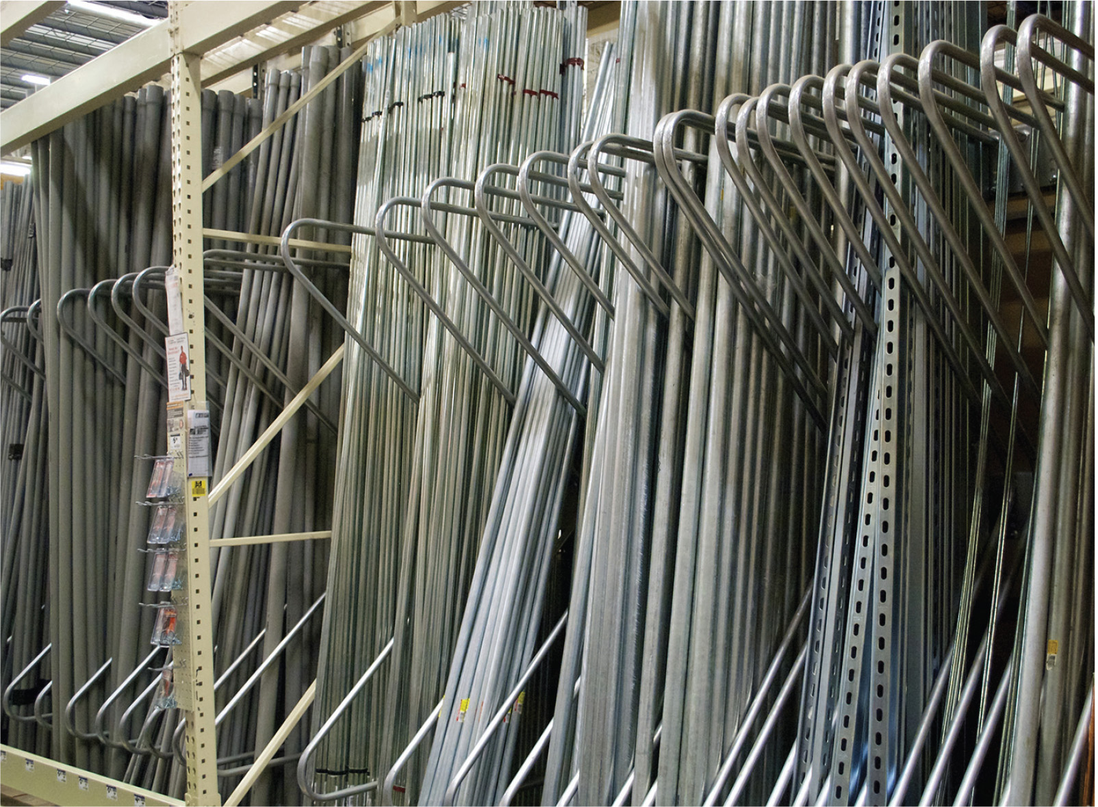
FIGURE 5-24 Type EMT is an excellent general-purpose metal raceway for indoor or outdoor use.
Flexible Metal Conduit
Flexible metal conduit (Type FMC), shown in Figure 5-25, is a convenient multipurpose flexible conduit that is permitted in residential applications except wet locations, underground, or embedded in poured concrete. All cut ends must be trimmed or otherwise finished to remove rough edges, except where fittings that thread into the convolution are used. Type FMC is to be securely fastened in place within 12 inches of each box, cabinet, conduit body, or other termination, and it must be supported and secured at intervals not exceeding 4½ feet. Type FMC qualifies as an equipment-grounding conductor within limitations, but the best policy is to pull a separate green conductor for the purpose.
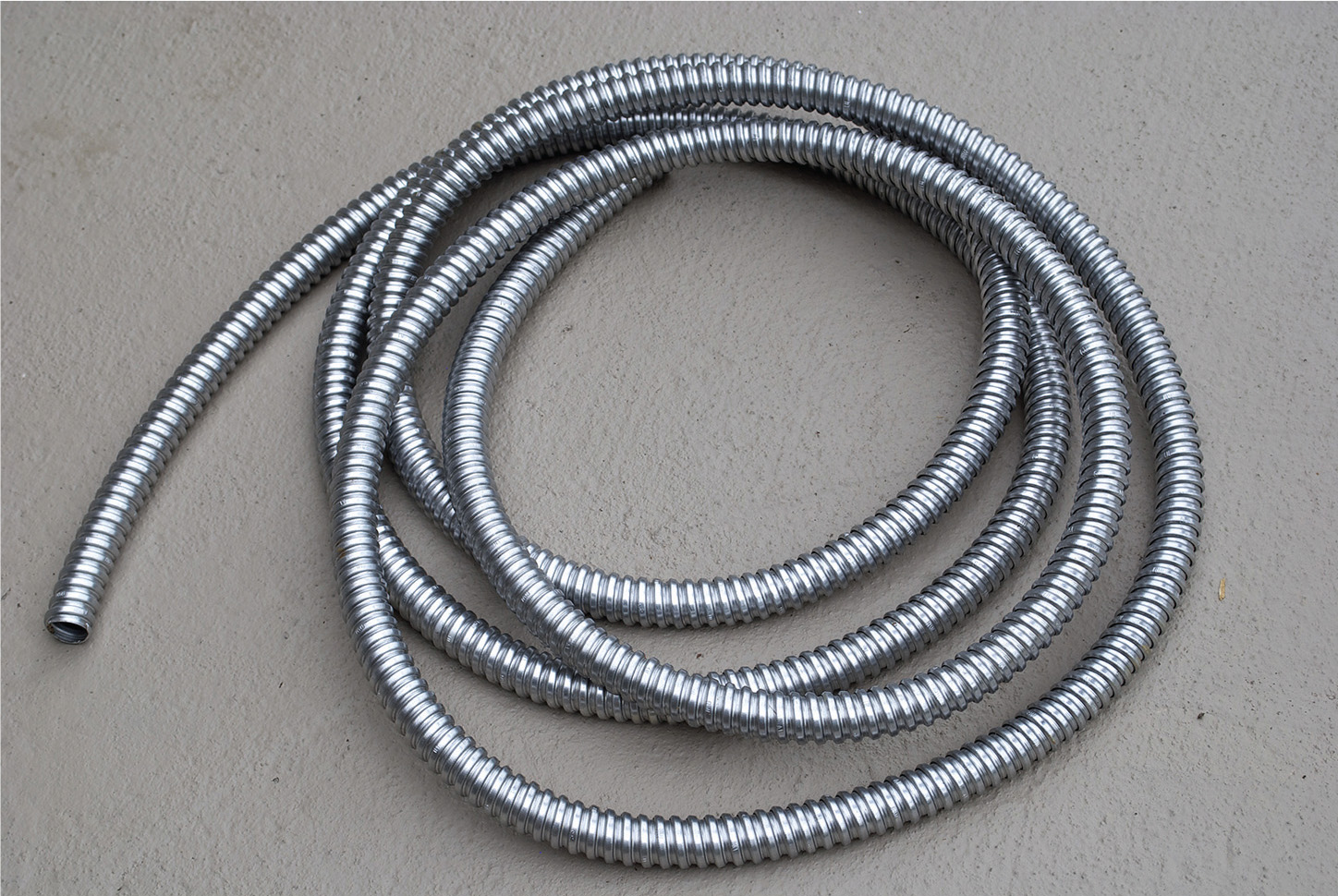
FIGURE 5-25 Type FMC provides excellent protection where flexibility is needed.