CHAPTER 14
![]()
Alternate Power Systems: Wind, Solar, and Fuel Cells
Every year, our planet is getting a little warmer. For those who live in cold areas, this may seem beneficial, but it is actually an enormous problem for everyone, and it goes way beyond discomfort. When ocean waters are heated, vast amounts of energy are injected into offshore weather systems. Together with glacial melting, which is going to raise sea levels, these events will conspire to take away our coastal lands.
A very few degrees of warming will disrupt established patterns of agriculture, fishing, and all sorts of human activities. Economic dislocations and widespread poverty will follow. We have to stop burning carbon to heat our buildings and power our vehicles—the sooner the better. Changes must be made. For now, it is looking like the changes will be incremental and highly localized.
Some Answers
There has been a lot of interest lately in alternate (i.e., non-carbon-based) energy systems, and the home crafter-electrician is very well positioned to participate. Tax and utility incentives in many locations make it affordable to build onto our homes the means to heat them, provide electricity, and power our vehicles. The technology exists to do this right now.
The fantasy of perpetual motion is not an answer. If in the future some quirk in quantum mechanics or a way to reverse the arrow of time and make entropy work for us should appear, that would change the situation dramatically, but for the time being, we have to work with what we have, which is two very abundant energy sources that are everywhere on Earth—wind and sun.
Wind
Many of us have entertained the notion of fitting some sort of rotor to a surplus automotive alternator, building a wind turbine, and putting a stop to electric bills forever. This is part fantasy and part reality. The power that is produced within, let’s say, a Delco-Remy alternator is known as wild alternating current (ac). Because of the circular rotation of the armature, the waveform is an elegant sine wave that is free of harmonics and noise. But voltage and frequency fluctuate rapidly as the speed of rotation changes. The three-phase ac is rectified by means of a network consisting of six diodes inside the alternator so that the output is regulated direct current (dc) that is perfect for charging an automotive battery.
This sort of alternator can be used as the basis for a wind generator, but there are a few problems. First of all, the revolutions per minute produced by a wind-driven rotor are way too low to operate the alternator. In order to drive an automotive alternator at a speed where it would produce its rated power, a set of pulleys or a geared transmission would be necessary to increase the revolutions per minute.
It is possible to rewind the stator, replacing the existing windings with more turns of a smaller gauge wire. This is a job for a specialized motor shop unless you plan to dedicate yourself to a big task with little return. The total output still would be far too low for even a single household. Additionally, the automotive alternator would not have a weatherproof housing. Overall, the potential for building a usable wind generator from an automotive-type alternator is low.
As electric cars including hybrids become more prevalent, older cars and those that have been wrecked will end their days in junkyards. Many electric cars employ regenerative braking, whereby the car motor is used to slow the vehicle and simultaneously charge the battery bank as opposed to dissipating the energy as waste heat from the friction of brake pads and wheel hubs. As designs become more diverse and old electric vehicles are put out of use, it is likely that some of these motor-generators will find second lives as wind generators.
Meanwhile, the option of using factory-built wind-turbine equipment, as shown in Figure 14-1, is very appealing. Many of these highly engineered power plants are well suited for residential use. With public and private utility incentives, these installations are quite feasible.

FIGURE 14-1 A wind turbine configured to produce electricity.
Before deciding on a model, it is essential to evaluate the feasibility of the project and, if it is a go, to size the turbine. To do this, you will need to choose the best location. Naturally, it should be near enough to the house so that a long transmission line will not be needed. Also, it is very desirable to have the wind generator visible from a house window. The tower should be far enough from the house and any other buildings that the airflow is not disrupted because this makes for turbulence and less useful wind power. Similarly, nearby trees or other objects will reduce output. (Don’t forget that trees will continue to grow during the life of the installation.) A tall tower will help to overcome these limitations, and if there is a knoll or upslope location for the wind turbine, this is a plus.
Choosing the Site
A temporary pole with an anemometer will help in evaluating the site. A wind-direction indicator is also useful. Sustained unvarying winds that do not shift direction constantly are far better than brief, powerful gusts.
The wind-turbine manufacturer will have documentation that includes wind-speed requirements for different power outputs, so you will want to evaluate your needs and choose the appropriate model. The height of the tower is an important variable. An excessively high tower will be an expensive and inconvenient burden, but on the other hand, the wind quality in terms of sustained speed and lack of turbulence improves with distance above grade.
You should contact the local planning board or regulatory authority early in the planning stage to determine whether there is a height limitation, property-line setback, or minimum lot size that needs to be observed. Tax and electric-rate incentives should be investigated at this stage, and if it is a cogeneration project, the utility should be contacted in advance.
In most jurisdictions, the National Electrical Code (NEC) or other code governs every detail of a nonutility wind-generator installation. Previous NEC editions covered only small wind electric generators, defined as up to and including 100 kW of output. This limit was removed from the 2014 NEC, so now any nonutility installation must comply. In the early planning stages, you should carefully review NEC Article 694, “Wind Electrical Systems,” to make sure that nothing is neglected. As an overview of this article, here are some definitions:
• Charge controller is equipment that controls dc voltage or current or both used to charge batteries. Where a battery backup system is used, a good charge controller will contribute to a safe and reliable installation. It prevents overcharging, which can damage batteries and release hydrogen with a risk of explosion and fire.
• Diversion charge controller, in conjunction with the charge controller, further protects the battery bank from the risk of overcharging. When the batteries are fully charged and output exceeds demand, excess power is diverted to a dummy load.
• Guy is a cable that braces a wind turbine tower so that it will not buckle during heavy winds. Some towers are sufficiently strong and have adequate concrete foundations that guys are not needed.
• Inverter output circuit consists of the conductors between the inverter and service equipment or another power source.
• Maximum output power is the greatest 1-minute average power output a wind turbine produces in normal steady-state operation. Instantaneous power output will be higher at times. This amount determines the size of the inverter, rectifier, and associated wiring.
• Maximum voltage is the highest voltage the wind turbine can produce, including open-circuit conditions. This figure also plays a role in selection of the inverter and rectifier.
• Nacelle is the enclosure that houses the wind turbine, including the alternator but not the rotor.
• Rated power is the output power of the wind turbine at a wind speed of 24.6 mi/h.
• Wind-turbine output circuit consists of the circuit conductors between the internal components of the wind turbine and other equipment.
NEC Section 694.7, “Installation,” states that wind-turbine systems are to be installed only by qualified persons. Because there is no homeowner exemption for this requirement, as there is for electrical licensing, the home crafter-electrician will have to become qualified. This is an important mandate, and it is in your interest to become qualified before you perform a wind-power installation. An exact mechanism is not specified. In NEC Article 100, “Definitions,” qualified person is defined as anyone who has skills and knowledge related to the construction and operation of the electrical equipment and installation and has received safety training to recognize and avoid the hazards involved.
An installation requirement for wind-turbine systems is that a surge-protection device is to be placed between the installation and any loads served by the premises electrical system. Also, it is provided that wind-turbine electrical system currents are to be considered continuous. The reasoning behind this requirement is that very often the wind can be expected to blow continuously for over 3 hours.
The inverter output of a stand-alone (i.e., non-utility-connected) wind-turbine electrical system is permitted to supply 120 volts to single-phase, three-wire 120/240-volt service equipment or distribution panels where there are no 240-volt outlets. Multiwire branch circuits are precluded for obvious reasons. For a 120-volt wind generator, this is a common arrangement to permit full use of the box. The one hot, ungrounded conductor from the inverter is connected to both bus bars in the distribution panel.
NEC Article 694, Part III, “Disconnecting Means,” is crucial to getting it right in wiring a wind-turbine electrical system. This is so because the turbine leads always must be considered live, even when the turbine is not turning and when a blocking diode, shown in Figure 14-2, is in place.

FIGURE 14-2 Schematic of a dc wind turbine, blocking diode with motoring switch (for testing purposes), and battery bank.
Above all, means must be provided to disconnect all current-carrying conductors of a wind-turbine electrical power source from all other conductors in the building. The disconnecting means is not required to be suitable as service equipment. It is to consist of manually operable switches or circuit breakers that comply with all the following requirements:
• They must be readily accessible.
• They must be manually operable without exposing the user to live parts.
• They must plainly indicate whether they are open or closed.
• They must have an interrupting rating sufficient for the circuit voltage and fault current available at the terminals.
• Where all terminals are capable of being energized in the open position, a warning sign is required.
• A disconnecting means is to be installed at a readily accessible location or adjacent to the wind-turbine tower on the outside of the building served or inside at the point of entrance of the wind-system conductors.
• A means must be provided to disconnect individual units such as inverter, batteries, and charge controllers from all ungrounded conductors of all sources.
NEC Article 694, Part IV, “Wiring Methods,” states that all wind-turbine output circuits that are in readily accessible locations and that operate at over 30 volts are to be installed in raceways. Dc wind-turbine output circuits installed inside a building are to be in metal raceways or metal enclosures from their entry into the building to the first readily accessible disconnecting means.
NEC Article 694, Part V, “Grounding,” provides that exposed non-current-carrying metal parts of towers, turbine nacelles, other equipment, and conductor enclosures are to be connected to an equipment-grounding conductor. A wind tower is to be connected to one or more auxiliary grounding electrodes. This is in addition to the premises electrical grounding system. This auxiliary grounding electrode can be a ground rod, a tie to the foundation rebar, or another acceptable grounding electrode.
These are the principal NEC requirements for a nonutility wind-turbine electrical system. Next, we shall turn to the solar photovoltaic (PV) electrical system. After that, we’ll consider battery backup and utility cogeneration because these topics are applicable to both wind and solar systems.
Sun
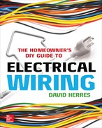
In some ways, solar power generation, as shown in Figure 14-3, is preferable to wind power generation. For one thing, it lies flat rather than sticking up in the air, so it is less intrusive. With no moving parts, there is less maintenance, and if repair work is needed, there is no need to climb a tower. Often it is easier to find good sun than to find good wind.
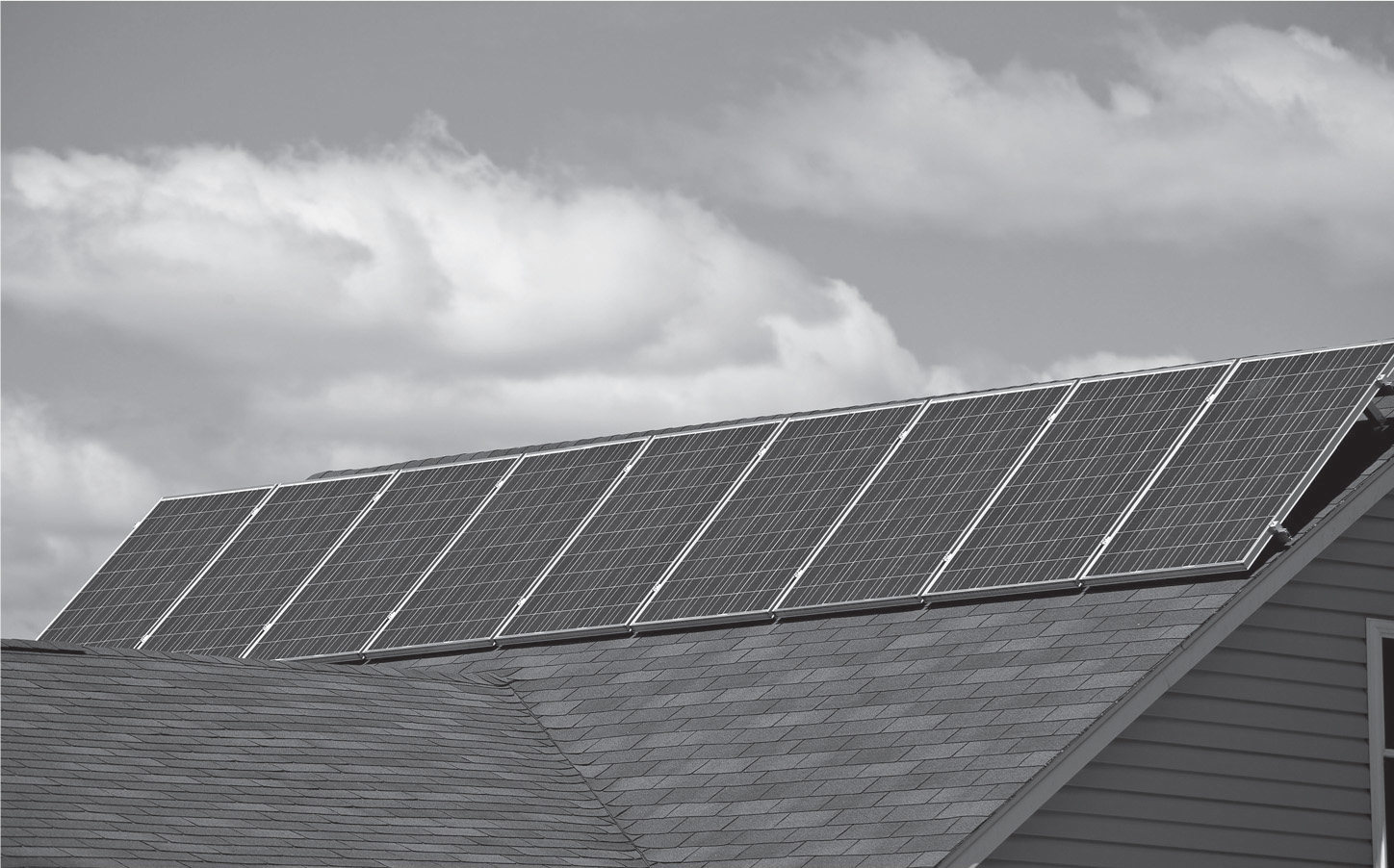
FIGURE 14-3 A roof-mounted solar array is unobtrusive.
Solar-cell prices have been in freefall in recent years, and there is every reason to anticipate that this trend will continue. Ongoing research and economies of scale are coming together to improve efficiency and reduce manufacturing costs, so increasingly it is looking like solar PV power will replace fossil fuels as the dominant energy-producing technology. The principal kind of solar PV cell is crystalline silicon, as opposed to amorphous or thin-film silicon.
A solar PV cell is simply a diode that is packaged and manufactured in such a way that when light in a certain range of frequencies strikes the junction, the cell becomes forward biased and produces a steady dc at a low voltage. The power output of a single cell exposed to direct sunlight is low, but a large number of cells can be connected in series and parallel configurations that are capable of producing power limited only by the number of cells. Because a solar cell, electrically, is a simple diode, it has only two leads—an anode and a cathode. Wiring them to make panels and connecting the panels to make an array are accomplished using conventional copper wire splicing and joining techniques, and the output is a two-wire dc of whatever voltage desired, unless it is a center-tap situation, in which case there is a positive pole, negative pole, and neutral that may be grounded.
There is such a thing as a tracking array, powered by one or more servomotors, that moves slowly throughout the day in order to face directly toward the sun at all times. Most arrays, in the interest of simplicity, are stationary, the angle carefully chosen with reference to the site’s latitude to maximize output.
A strange thing about solar cells is the way their output is influenced by the ambient temperature. Most physical and chemical reactions accelerate with a rise in temperature, but the output of solar cells decreases as the temperature goes up. For this reason, northern locations, even where there is less sunshine, may be favorable sites for solar PV power generation.
Solar PV installation and repair are generally less hazardous than working on a wind turbine. There is not the high tower to climb, and you don’t have to worry about the rotor that could start turning without warning. But, when the sun is shining, the terminals of a PV array are live, beginning when packing material is removed. Today’s solar cells produce output even in diffuse ambient light, and it is not practical to locate a disconnect in or on each panel, so there is a potential for shock. Some technicians place an opaque shield over each panel until the assembly is installed and wired to a disconnect, but this solution can be unwieldy and makeshift.
NEC Article 690, “Solar PV Systems,” resembles Article 694, “Wind Electrical Systems,” but there are a few differences due to variations in the electrical characteristics of the two systems. Article 690 begins with definitions. The principal terms, excluding those covered in Article 694, are
• Alternating-current module is a complete, environmentally protected unit that consists of solar cells, optics, inverter, and other components, not including the tracker, that is designed to output ac power when exposed to sunlight.
• Array is a mechanically integrated assembly of panels or modules, including the support structure and foundation, tracker, and other components as required to form a dc-producing unit.
• Bipolar photovoltaic array is a PV array that has two outputs, each having opposite polarity to a common reference point or center tap.
• Blocking diode is a diode used to block reverse flow of current into a PV source circuit.
• Building-integrated photovoltaics are defined as PV cells, devices, modules, or modular materials that are integrated into the outer surface or structure of a building and serve as the outer protective surface of that building.
• Module is a complete, environmentally protected unit consisting of solar cells, optics, and other components, exclusive of the tracker, designed to generate dc power when exposed to sunlight.
• Monopole subarray is a PV subarray that has two conductors in the output circuit, one positive and one negative. Two monopole PV arrays are used to form a bipolar PV array.
• Panel is a collection of modules mechanically fastened together, wired, and designed to provide a field-installable unit.
• Photovoltaic output circuit is defined as circuit conductors between the PV source circuits and the inverter or dc utilization equipment.
• Photovoltaic power source is an array or aggregate of arrays that generates dc power at system voltage and current.
• Photovoltaic source circuit is defined as the circuits between modules and from modules to the common connection points of the dc system.
• Photovoltaic system voltage is the dc voltage of any PV source or PV output circuit.
• Solar cell is defined as the basic PV device that generates electricity when exposed to light.
• Solar photovoltaic system is the total components and subsystems that, in combination, convert solar energy suitable for connection to a utilization load.
• Subarray is an electrical subset of a PV array.
There are many similarities between wind-turbine and solar PV installations but also some important differences. Both are used in stand-alone and utility-interactive configurations. Solar power, however, is dc and requires no rectification. For stand-alone applications, the backup battery banks or other energy-storage systems are similar, and both require disconnects and blocking diodes to prevent feedback. Inverters, to create ac for local use or synchronized ac for cogeneration with the utility, are more elaborate in wind systems because of the more rapid fluctuations and high peaking due to gusting winds.
NEC Mandates
NEC Section 690, Part II, “Solar System Circuit Requirements,” provides information on voltage correction at various ambient temperatures. As noted previously, solar-cell output is greater at lower temperatures, especially when there is no load. And because open-circuit voltage determines the voltage rating of cables, disconnects, overcurrent devices, and so on, the NEC provides Table 690.7, which lists voltage correction factors for silicon modules. The temperature range in this table is –40 to 77°F. The table refers to the lowest ambient temperature for the region. Multiply the open-circuit voltage by the correction factor to specify the system components.
NEC Section 690.8, “Circuit Sizing and Current,” provides information for determining the maximum current in a solar PV circuit. For PV source circuits and output circuits, it is the sum of parallel-module short-circuit currents multiplied by 125 percent. For inverter output circuits, it is the inverter continuous output current rating, taken off the nameplate. For a stand-alone inverter input circuit, it is the stand-alone continuous inverter input current rating when the inverter is producing rated power at the lowest input voltage.
NEC Section 690.9, “Overcurrent Protection,” refers all questions regarding solar PV system overcurrent protection back to the generic NEC Article 240.
NEC Section 690.11, “Arc-Fault Circuit Protection (Direct Current),” requires a listed arc-fault circuit interrupter (AFCI), PV type, for in-building PV systems with dc source circuits or dc output circuits operating at or above 80 volts.
NEC Part III, “Disconnecting Means,” requires disconnects to be placed at all critical locations within the PV system as in a wind system. NEC Part IV, “Wiring Methods,” resembles requirements for wind systems. PV source and output circuits operating at over 30 volts are to be installed in raceways where the location is readily accessible. Because raceways cannot be attached directly to PV modules, the area may have to be fenced off unless the modules are high enough to be considered not readily accessible. What is decisive is whether a ladder is needed.
Single-conductor cable, not Code compliant in most applications, is permitted in exposed outdoor locations in PV source circuits for modular interconnections within the PV array. For most electrical wiring, the NEC prohibits conductors smaller than 14 American Wire Gage (AWG), but 16 and 18 AWG can be used for modular interconnections, provided that ampacity requirements are observed.
PV wiring is not to be installed within 10 inches of roof decking or sheathing unless it is directly below the PV modules or related equipment. It is permissible to run the circuits perpendicular to the roof surface. The purpose of this requirement is to limit risk of shock when firefighters use power saws to cut holes in roofing to vent flames. This hazard is a result of the fact that the PV conductors are not deenergized by a disconnect.
NEC Part V, “Grounding,” provides that one conductor of a two-wire PV circuit operating at over 50 volts is to be grounded. The same applies to the reference conductor of a three-wire bipolar PV system.
Cogeneration or Battery Backup?
Both wind-turbine and solar PV power systems can exist as either stand-alone or cogeneration installations. Cogeneration depends on a connection to the utility line, and this depends on it being close by. The electric company invariably figures that a line extension should be built at the customer’s expense, and the cost is always higher than expected. This is the rationale for a stand-alone system.
A stand-alone system usually has a battery backup or other type of energy-storage system. Energy storage can take many forms—compressed air, water pumped to a higher level, a railroad car towed upslope, a capacitor bank, or a huge flywheel. The most widely used energy-storage medium is a bank of lead-acid batteries. This is the big problem in a stand-alone system. The batteries, for a bank of any size, are expensive, and their lifespan is finite. Over a period of time, the battery expense may be greater than the cost of a wind or solar installation.
For this reason, utility cogeneration, where a tie to the grid is feasible, is usually the way to go. But this depends on the cooperation of the utility. Because utilities are regulated by a public commission, they often have no choice in the matter. (The operative concept is “kicking and screaming.”)
For cogeneration to work, there has to be an electrical service at the building. The wind or solar output is connected to the utility supply. When the wind or solar output exceeds premises demand, the excess is backfed into the grid. Once this is set up, it requires no human intervention and is completely automatic. The utility transformer on the pole, fed in reverse direction, steps up the voltage to match the voltage in the distribution line, and this energy participates in powering all other connected loads. By means of reverse metering, as shown in Figure 14-4, the customer’s net contribution of power to the grid is determined, and the utility is obliged to credit this amount to the customer’s account and issue a payment if there is a surplus. The amount credited can be figured at the wholesale price of electricity or at the retail rate. This is determined by the regulatory authority and generally is not a decision that is made by the utility.
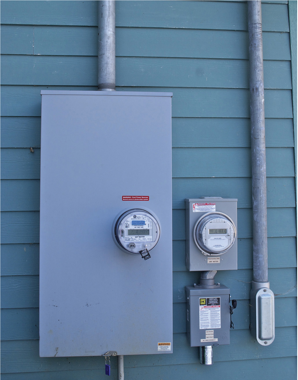
FIGURE 14-4 Reverse metering used with a cogeneration hookup. Notice the disconnect!
Wind or solar PV power is dc. With or without energy storage, it can be used to power dc loads. Some loads, such as incandescent lights, do equally well on ac or dc. Home appliances with motors require a standard house current ac, although dc models are available at a premium price. Because most users prefer the convenience of being able to plug in a standard appliance, computer, or power tool, the solar or wind output is usually changed from dc to ac. What is wanted is a well-regulated ac whose voltage corresponds to a sine wave.
The equipment that performs this conversion is known as an inverter. The first inverters were rotary machines that can be described as motor generators. They resemble electric motors with no output shafts, just closed-end bell housings. A rotary inverter contains dc motor and ac generator windings. Terminals on the outside of the housing allow for connections of the dc input and the ac output. A rotary inverter provides a high-quality sine-wave output, but because it is a mechanical device with moving parts, it is expensive to manufacture and may require maintenance. For this reason, most inverters currently deployed are electronic devices, the sine wave being created by semiconductors. The outputs of the first electronic inverters were crude by today’s standards, square-wave approximations of the sine wave. This sort of electricity is good for incandescent lighting and similar resistive loads, but a motor or transformer will protest if fed such a diet by overheating and running at reduced power. Over the years, solid-state inverters have been developed that produce outputs more closely resembling a pure sine wave, and today, there is no problem in powering ac motors.
For the purpose of cogeneration with a utility, a premises with solar PV, wind turbine, or any other alternate power source must feed into the grid electrical energy that is of the same voltage and frequency as the utility power. Moreover, the waveforms must be precisely synchronized. This means that the positive and negative peaks must occur at the same time. The equipment that makes this possible is known as a synchronous inverter. By means of internal circuitry, the synchronous inverter continuously samples the utility power at the connection and creates an output that synchronizes with it. This equipment is a factory-made unit that is contained within an enclosure designed for either an indoor or outdoor location. The synchronous inverter is sized according to the output and type (e.g., wind, solar, or other) of the alternate source. It also has the failsafe ability to disconnect the alternate source from the utility supply, in the manner of a transfer switch, in the event of an outage. This is necessary to protect utility workers from backfeed that would energize distribution lines that are being repaired.
Increasingly, wind-turbine and solar PV systems are being sold as packages that include, where desired, synchronous inverters for the purpose of cogeneration. If you are retrofitting a synchronous inverter to an older solar PV or wind-turbine electrical system, you will need to match the characteristics carefully. Beyond this, it is just a question of hooking up the external connections correctly because all terminals will be marked.
Where there is the opportunity to make a cogeneration hookup, a battery backup installation should not be considered because the continuous maintenance cost will be an ongoing liability. Backup battery banks resemble solar arrays in the sense that while you are working around them, you must consider them to be live at all times. The battery bank is to be provided, as previously noted, with a disconnect. When doing battery maintenance, however, this device will not protect the worker because precisely where the maintenance is needed is upstream from the disconnect.
A characteristic of dc is that the electrical connections are prone to corrosion. Oxidation is a reversible electrochemical reaction. In an ac connection, because the polarity is continuously reversing, the oxidation does not accumulate as in a dc connection. Moreover, vented lead-acid batteries release acidic vapors into the surrounding air, and some of this acid finds its way into the individual battery terminations. For these reasons, periodic battery bank maintenance involves taking apart and cleaning battery terminations. In the process, there is the possibility of dropping a metal tool in such a way that it shorts out part or all of the battery-bank circuit. Not limited by branch-circuit conductors, an intense arc-fault can ensue, resulting in personal injury or fire. Such maintenance should not be performed until long after the last charging cycle so that any hydrogen gas will have time to dissipate. A battery bank should be in a dedicated room with ample working space and good ventilation, and this has to be considered as part of the cost of a battery backup system.
Because batteries lose their charge over time as a result of finite internal impedance, they are inherently inefficient. A larger battery bank has greater losses. The battery bank should be sized not too large and not too small. Battery banks are appropriate only for stand-alone applications and not for cogeneration installations. In all cases, lead-acid batteries are the only cost-efficient type. Lithium-ion, nickel-cadmium (NiCad), and other advanced-type batteries are too expensive to consider for backup applications.
Notes on battery-bank maintenance:
• Lead-acid batteries contain an electrolyte that is a mixture of sulfuric acid and water. The greater the charge in the battery, the more acidic is the mixture. Electrolyte levels should be carefully checked and maintained not only because when the level goes down there is less electrical storage capacity but also because if part of a plate is exposed to air and acid fumes, it will rapidly oxidize. This reduces electrical capacity. Also, these areas of the plates will swell, reducing the spaces between them and internal impedance so that the battery will not hold a charge.
• If a lead-acid battery is left in a discharged state over a period of time, the plates acquire a sulfur-compound coating. This is known as sulfation, and the battery will not take a charge. Sulfation sometimes can be reversed by applying a dc charge for a period of time. Also, lightly tapping on the outside of a battery case with a rubber mallet sometimes can cause the coating to fall off the plates so that it accumulates harmlessly at the bottom below the plates. Overall, sulfation leads to shortened battery life.
• The amount of charge in a battery cannot be measured directly with a voltmeter. A hydrometer has a rubber squeeze bulb that draws a sample of electrolyte out of the battery so that its specific gravity can be measured. The gauge is calibrated to show percentage of battery charge.
• Ample-sized battery terminals have less tendency to heat up when carrying heavy current—hence there is less corrosion.
• Battery posts and clamp-on terminations should be cleaned with a wire brush. Sandpaper will leave insulating particles embedded in the metal, making for reduced ampacity. Do not scrape terminations with a knife. Corrosion inhibitor can be used to good effect. Sometimes grease is used to keep out acid contamination. This should be applied only to the outside of the joint, not on mating metal surfaces. If it is heated, the grease will dry and make for a resistive joint.
• Once a week, lead-acid batteries should be given an equalization charge. This is about 10 percent higher than the charging voltage, and it should be applied for 8 hours. It makes for longer battery life by intentionally creating gas bubbles, which prevent layering and also mix the electrolyte. If an equalization charge is not applied periodically, there will be a more acidic mix near the top of the battery, resulting in shortened life. An equalization charge is not necessary for the battery in a moving vehicle, where bumps in the road agitate the electrlyte, preventing layering.
At best, lead-acid batteries deteriorate in time and need to be replaced periodically. On the other hand, barring lightning damage or other mishap, an electronic synchronous inverter will last indefinitely, so cogeneration, where possible, is the better choice.
Foundations for Wind Turbines and Solar PV Arrays
The concrete work for both wind turbines and solar arrays should be of the highest quality, although for different reasons. In the case of a wind turbine, it is a question of resisting the lateral thrust of the highest-velocity wind that will be encountered in the life of the installation. When a three-blade turbine is spinning rapidly, it offers the same resistance to the wind as a solid disk of the same radius. The sideward thrust of the wind will seek to overturn the concrete in the ground or separate the tower from it. Therefore, the tower must be very well anchored, and the concrete must be massive.
For a solar PV array, there is less tendency for the wind to disrupt the array because it is lower to the ground and not facing into the wind. But the issue with a solar PV array is that the concrete work should be absolutely stable so that accurate positioning of the panels is maintained. Moreover, if there is any misalignment, the installation will be unsightly.
The foundation for a wind turbine should be a cube or cylinder of concrete that extends deep into the ground, well below the lowest level frost could ever penetrate with no snow cover. Also, the deeper it goes, the better it will resist the horizontal thrust of the wind at the top of the tower. The top surface of the concrete should be sufficiently above the finish grade that water will not accumulate. It should slope ⅛ inch per foot for drainage. It should be troweled smooth (but not over troweled) to make a durable weatherproof surface.
Large anchor bolts should be provided so that the tower will never pull off the foundation. They should be electrically bonded to reinforcing rod within the concrete to create a Ufer grounding electrode that is better than ground rods.
For a solar PV array, the concrete foundation is usually formed by means of Sonotubes, heavy cardboard cylinders into which the cement is poured. For individual solar panels to be set at the same level, given the fact that the ground will be uneven, it is necessary for the Sonotubes to be set using a builder’s level or transit. The number of Sonotube footings per panel will depend on the size of the panels, the length and diameter of the tubes, the strength of the steel panel supports, and the height above grade of the panels. A solar array with this type of foundation is shown in Figure 14-5.
FIGURE 14-5 Sonotube concrete footings should not be too far out of the ground so as to limit pitting from the weather.
Sonotube construction has disadvantages, and many installations, where proper procedures are not followed, result in flawed final products. In areas where the ground freezes deep, the concrete footings can be lifted out of the ground, even if they extend far below the frost line. This is so because the ground freezes to the upper part of the concrete cylinder and lifts it out of the ground. This defect can be countered by using a long Sonotube that extends deep into the ground. Another technique is to make tapered footings using lumber or premade forms. In this way, the mass of the concrete is deep, and there is less surface area in the freezing zone. It is also helpful to backfill with a washed, screened, ¾-inch stone. Some builders install a plastic sleeve for the concrete cylinder. This prevents the freezing ground from gripping the footing. Still another technique is, in a separate pour, to make a subfooting for the Sonotube. It should be fairly thick and extend laterally beyond the cylinder. If the two pours are anchored by means of steel bolts, there will be less tendency for the concrete to heave out of the ground.
Many finished Sonotube footings exhibit severe surface pitting in the portion above grade. Not only is this unsightly, but it also sets the stage for more deterioration down the road as water penetrates into the concrete and freezes. These rat holes, as they are called, are prevented by tamping the fresh cement immediately after it is poured. A long stick is used to poke the cement so that air bubbles rise to the surface and are released. The problem with a Sonotube is that these bubbles rise from the bottom and collect at the top. By the time all the air bubbles are out, the cement has been so overtamped that segregation occurs. This means that the stone aggregate sinks to the bottom, water comes to the top, and nowhere is there a proper mix. Again, the end result is badly pitted concrete work. The solution to this problem is to place the cement in a series of individual 12-inch lifts so that the air is released without overtamping. For a durable top surface, it should be sloped slightly to shed water away from the anchor bolts. Then the surface should be smoothed nicely without overtrowelling.
Fuel Cells
If hydrogen and oxygen atoms are brought close together, they join spontaneously to form water molecules. In the process, for each molecule of water that is formed, an electron is released in addition to a quantity of energy in the form of heat.
A fuel cell takes advantage of this simple reaction to generate electricity. Each fuel cell consists of a cathode, an anode, and an electrolyte. At the anode is a catalyst, frequently platinum. The catalyst facilitates the electrochemical reaction, but it does not take part in it. It is not consumed and does not have to be replenished.
In the most common types of fuel cells, hydrogen is oxidized at the anode. The only waste product is water, so the fuel cell is pollution-free, and there is no contribution to global warming. If dc electricity is passed through water, hydrogen is produced at the cathode and may be compressed and bottled in cylinders or piped to another location. (A useful by-product is oxygen, which is produced at the anode.) If the dc electricity is produced by a solar PV array, there is the potential to obtain storable energy and use it locally or to power mobile vehicles.