
4
The LonWorks® Control Networking Platform
The LonWorks series of networking protocols were developed by Echelon® Corporation for the needs of control and automation applications and are now managed by the LonMark® International trade group. The LonWorks platform was initially developed in an effort to move away from the proprietary centralized control model, where a central controller receives all measurements from remote sensors and sends all commands to remote actuators. In an effort to eliminate the controller as a single failure point and increase the efficiency and power of control systems, the LonWorks platform introduced a concept of “connection” enabling devices to exchange data directly, using a subscribe/notify model.
At the physical layer, the LonWorks platform is media independent; including media types for copper pairs (wires) and power lines, radio, infrared light, and optical fiber.
The LonWorks platform is one of the most popular protocols for building and industrial automation, claiming over 90 million installed devices.
4.1 Standardization
In 2008, LonWorks also was approved as ISO standards: ISO/IEC 14 908-1, -2, -3, and -4 for the protocol, twisted-pair channel, power-line channel, and IP-tunneled channel, respectively.
4.1.1 United States of America
The communication protocol (a.k.a., the LonTalk® protocol; Echelon's trade name) was submitted to ANSI in 1999 and accepted as a standard for control networking (ANSI/CEA-709.1; originally EIA-709.1). Shortly after, the power line and twisted-pair physical layers were accepted as part of the ANSI standard series.
4.1.2 Europe
The European Committee for Standardization (CEN) standardized the protocol for “buildings” use in 2005. Then in 2007, the LonWorks platform became part of the Application Interworking Specification (AIS) recognized by the European Committee of Domestic Equipment Manufacturers (http://www.ceced.eu/) for Household Appliances Control and Monitoring.
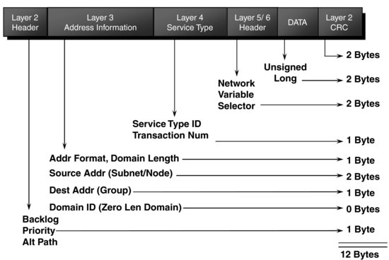
Figure 4.1 A typical ISO/IEC 14 908-1 Packet. Reproduced by permission of © Echelon Corporation.
4.1.3 China
In China the LonWorks platform is both a national standard in the category of “controls” (GB/Z 20 177.1-2006) and in the category of “buildings” (GB/T 20 299.4-2006).
4.2 Technology
Figure 4.1 shows the structure of a LonWorks packet, including data fields used by each protocol layer. The protocol layers are detailed in the following sections.
Figure 4.2 LonWorks media channels (most common in bold). Reproduced by permission of © Echelon Corporation.
4.2.1 Physical Layer
The LonWorks protocol is media independent, and assumes only a physical layer that can transmit binary signals, called a channel. Specific transceivers are required for each underlying physical layer. The series of standards defines transceivers for twisted pair, link power, power line, radio frequency, optical fiber, coaxial cable, and infrared media channels (Figure 4.2, the complete list can be found at http://www.lonmark.org/spid). Most of the transceiver channels use differential Manchester encoding, where each “1” is transmitted as a polarity reversal for a full period, and each “0” is represented as two polarity reversals during a single, full period. This type of encoding ensures that there is no continuous component in the transmission (it averages to 0 regardless of the information transmitted), and that connections – particularly those using two wires – that not need to care about polarity.
Each physical communication link may be interconnected by means of a LonWorks router, or extended by means of a physical layer repeater. Channels connected by a repeater form a segment.
4.2.2 Link Layer
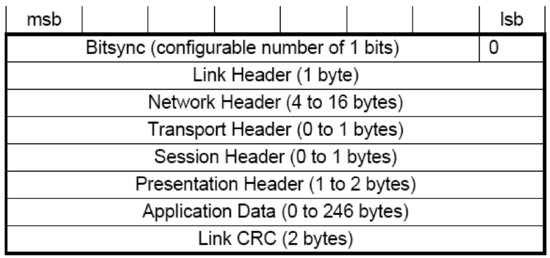
The protocol's link layer provides cyclical redundancy check (CRC) error checking in order to detect most transmission errors; an access, collision avoidance and priority mechanism; and a data-frame format (Figure 4.3).
Figure 4.3 A typical LonWorks data frame, least significant bits are transmitted first. Reproduced by permission of © Echelon Corporation.
4.2.2.1 Access and Priority Mechanism
The media access control (MAC) algorithm employed is carrier-sense, multiple access (CSMA), in a variant called p-persistent CSMA: A LonWorks networking device is required to establish that the transmission medium is idle before it can start communicating (this is common to all CSMA protocols). In addition, in order to reduce the probability of collisions, it will begin to transmit, with probability p, in one of 1/p predefined time slots (called beta-2 slots, during typically from 2 to 30 bit times). The number of time slots is dynamically adjusted based on the network load: with more time slots (smaller p), the network works better during high loads, but this adds to the transmission delay compared to fewer time slots. Each LonWorks networking packet includes the number of acknowledgments expected as a result of sending this packet, which allows receiving devices to estimate the upcoming network load and adjust the number of beta-2 slots accordingly. Adjustments are made as multiples of 16 (n×16), where n is called the current transmission-channel backlog. The required increment is indicated in the link header delta backlog field (Figure 4.4).
Figure 4.4 Details of the link layer header. Reproduced by permission of © Echelon Corporation.
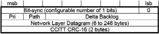
Some transceivers can send over two channels for redundancy purposes; the desired channel for a packet is indicated by the Path bit of the link header (Figure 4.3).
On each channel, a fixed number of the first beta-2 time slots (up to 127 time slots) can be allocated to priority packets. Devices can send both priority packets and nonpriority packets. The Pri bit (Figure 4.3) of the link layer header indicates whether the packet is a priority packet.
4.2.3 Network Layer
The network layer provides the message-delivery mechanisms.
Each device (“node”) is identified by a unique 48-bit identifier, called the unique node identifier (UID) or the unique_node_ID, within device memory structures. It is also, colloquially and historically, known as the neuron ID, or neuronID. The UID does not change over the lifetime of the device. It is normally used only when the device is first inserted in the network, before it has been assigned a logical network address. This facilitates the replacement of a device by a new device of the same type, which will have a different UID but will be assigned the same logical network address as the replaced device. The UID is also utilized for applications requiring authenticated messaging service (for higher-security needs).
The protocol uses hierarchical addressing, and defines the domain (0, 1, 3, or 6 bytes), subnet (8 bits), and node (7 bits) subaddresses. Each device is assigned a unique nodeID in each subnet. Therefore there may be up to 32 385 devices (255 subnets × 127 nodes) per domain. The devices of a single domain or subnet may be on various channels; and devices from multiple domains may coexist on the same channel.
The source of each message is contained in the address field of the header, and specifies the sending node subnetID and GroupID (first two bytes). The target of a message may be, depending on the header Addr field value:
- A single node: the header comprises a 2-byte destination address specifying the subnetID and nodeID (header Addr format=2) or a 7-byte address specifying the destination subnetID and neuronID (header Addr format field=3).
- All devices in a subnet (3-byte address, header Addr format field=0).
- All devices in a domain (3-byte address, subnetID=0, header Addr format field=0).
- A group: the protocol defines group addresses (2-byte domainID, and 1-byte groupID, header Addr format header field=1), so there may be up to 256 groups per domain. Such addresses may be used to address groups of devices on different subnets. There is a maximum of 64 devices per group for acknowledged device-to-device messaging services and no limit for unacknowledged messaging services.
The packet format field specifies whether the packet is a transport packet (packet format field value = 0), a session packet (1), an authenticated packet (2) or a presentation packet (3).
4.2.4 Transport Layer
The protocol's transport layer provides the end-to-end reliability mechanisms. The protocol offers four basic types of messaging service, depending on the desired tradeoff between reliability and efficiency:
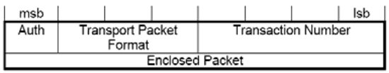
- Acknowledged (header transport packet format field = 0, see Figure 4.5): messages are sent in the context of a transaction identified by a transactionID. Each receiver sends an acknowledgment message (header transport packet format field = 2) with the transactionID. If not all acknowledgements have been received (until a configurable timeout), the message is retransmitted with the same transaction ID.
Figure 4.5 The network header format. Reproduced by permission of © Echelon Corporation.
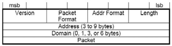
Figure 4.6 Transport layer header details. Reproduced by permission of © Echelon Corporation.
- Request/response: the request/response service is managed by the session layer.
- Repeated (header transport packet format field = 1): each message is repeated several times so that the probability of a device failing to receive one of the messages is reduced. However, the target devices do not acknowledge these messages, so the service is not fully reliable. Echelon Corporation estimates that 3 repeats results in a successful delivery probability greater than 99.999%. This service is useful for group addressing to large groups.
- Unacknowledged: the message is sent as “best effort” only and the sender is not notified if the message is lost en route. This service is useful for periodic data reporting from sensors.
The device can select any of the mechanisms listed above to transport its presentation layer messages.
For authentication to work (Auth bit in the transport header set to 1, see Figure 4.5), a 48-bit key (one per domain) must be configured in each device sending or receiving authenticated messages. The authenticated message is sent as a normal message from A to B but before acting on this message, B will authenticate the message by challenging A. The challenge includes a random number and A is expected to reply with a hash (encrypted encoding) of the secret domain key and the challenge. B computes the same hash locally and compares the result with the challenge response of A. If they are identical, B successfully acknowledges the original message.
4.2.5 Session Layer
The session layer replaces the transport layer when the packet format field of the network layer is set to 1 (Figure 4.5). It offers authentication (see transport layer) and a request/response service.
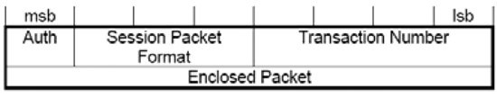
Like the acknowledged messaging service, the request/response service is useful when a message is sent to a device or group of devices and individual responses are required from each receiver. The request message (session packet format=0, see Figure 4.6) may either be resent until all responses (session packet format=2) have been received (the transaction number provides the acknowledgment mechanism), or it may be duplicated several times to minimize the risk of packet loss. The responses from a request/response transaction, unlike the simple, low-level acknowledgment from an acknowledged messaging service, usually include application-level response data.
Figure 4.7 The session layer header format. Reproduced by permission of © Echelon Corporation.
The enclosed packet data are formatted as a presentation-layer message.
4.2.6 Presentation Layer
4.2.6.1 Presentation-Layer Messages
The presentation layer defines the data-interpretation conventions of the protocol: it uses messages that are transported and retransmitted by the lower layers. Except for specific needs, most applications typically exchange data using network variable messages, except for some specific needs (file transfer, self-installation, etc.) or when there are communications requirements beyond those specified by the network variable messages.
The LonWorks networking presentation-layer messages begin with a one-byte message code that defines the type of data contained within the message (Table 4.1), followed by 0 to 277 bytes of data.
Table 4.1 LonWorks presentation-layer message types
| Message Type | 1 byte Message code | Usage |
| User Application Message | 00-2F | Message payload includes a 6-bit message code, followed by data. The applications exchanging application messages must agree on the interpretation of the message codes. |
| Standard Application Message | 30-3E | Same as User application messages but using the standard message codes used for standard application-layer services (data log, file transfer, and self-installation functions). |
| Foreign-Frame Message | 40-4E | Arbitrary data, which may encapsulate other protocols. |
| Network Diagnostic Message | 50-5F | |
| Network-Management Message | 60-7F | |
| Network Variable Message | 80-FF | Identifier that identifies the data as a data value (or data structure) of 1 to 31 bytes that may be shared by multiple devices on a network. |
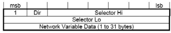
Figure 4.8 Format of a LonWorks network variable message (carried by the transport/session layer). Reproduced by permission of © Echelon Corporation.
4.2.6.2 Network Variables and the LonWorks Subscribe/Notify Model
Network variables are essential interfaces of most LonWorks networking devices. Network variables (Figure 4.7) have a direction (input to receive data, output to send data), type (scalar or aggregate of several fields), length, a self-documentation string. They are identified by a network variable index on the device, and are identified by a 14-bit network variable selector (0-3FFF) over the network (maintained in a configuration table on each device). A single network variable index can be associated to several network variable selectors on the same device; in which case, one is called the primary network variable selector and the others are aliases. Network variables’ values are exchanged over the network by network variable messages (Figure 4.9).
Figure 4.9 Example of devices exchanging information through connections. Reproduced by permission of © Echelon Corporation.
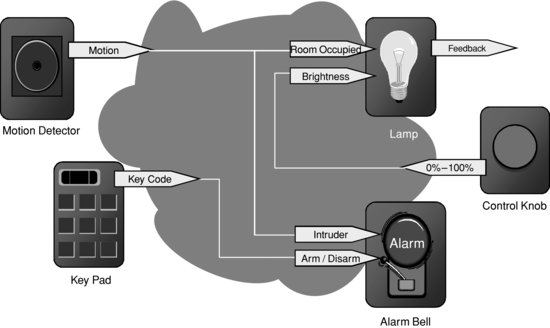
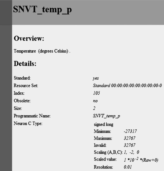
Figure 4.10 Example specification of a LonMark standard network-variable type (SNVT_temp_p). Reproduced by permission of © Echelon Corporation.
The LonWorks protocol provides two primitives to poll network variables over a network: one of which can poll multiple devices simultaneously using the network variable selector and one targeted to a single device using the network variable index.
The protocol also has a native subscribe/notify model – a key feature that supports the claim that the networking platform facilitates networks designed without central points of failure. Network variables belonging to different devices can be connected if they have the same type and length, for example, a state output (type: switch-type) of a switch device may be connected to the switch-type input of a lamp. There are several types of connections:
- Unicast: single output to single input;
- Multicast out: single output to multiple inputs on several devices;
- Multicast in: multiple outputs on several devices to a single input.
Connections are created by a process called binding and are performed by a network-management tool or by the self-installation process of the device. When binding network variables, the protocol implementation of the device is configured with:
- The list of addresses of the other devices (or groups of devices) in the network expecting that network variable's value;
- The target network variable selectors.
The application on the device will only update the network variable, and the protocol implementation will ensure that it is sent to all configured target addresses (domain/subnet/node or group, using the appropriate network variable selector). See Figure 4.8 for an example network configuration showing several connections using network variables.
The network variable selector values 3000 to 3FFF hex are reserved for unbound network variables, with the selector value equal to 3FFF hex minus the network variable index. Selector values 0 to 2FFF hex are available for bound network variables. This provides a total of 12 288 network variable selectors for bound network variables. Each device can have up to 8192 network-variable aliases and 4096 of those bindable network aliases.
Standard network variable types (SNVTs, pronounced “SNIV-its”), specify standard data encodings (units, range, resolution, scaling, data structure, etc.) covering most common usage cases. The list of SNVTs includes over 200 types and covers a wide range of applications. The complete list is available at types.lonmark.org.
If an application requires a network variable type that is not a SNVT, device manufacturers can define custom network-variable types. These are called user network variable types (UNVTs).
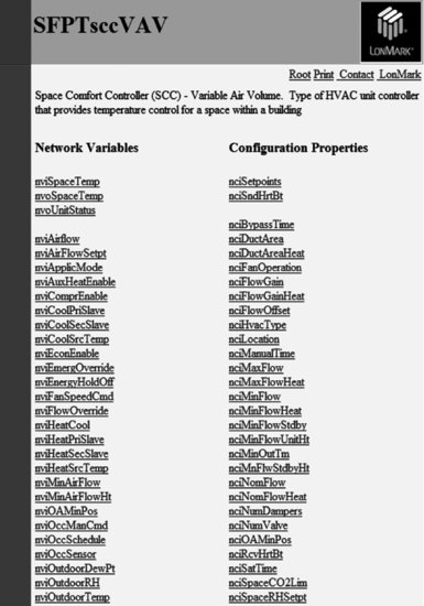
Figure 4.11 Example specification of a LonMark functional profile: the space comfort controller – variable air-volume controller. Reproduced by permission of © Echelon Corporation.
4.2.7 Application Layer
The network configuration and network-diagnostic services are defined by the protocol standard. The following list summarizes the standard application-layer services. Additional standard application-layer services (Figure 4.10) are published at www.lonmark.org
- Network configuration – configuration of the network attributes of a device (network address and binding information for the device's network variables).
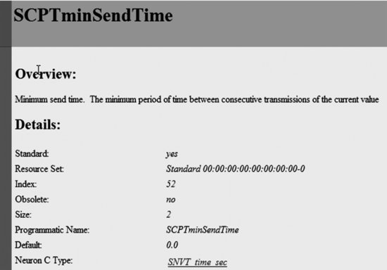
Figure 4.12 Example definition of a standard configuration-property type (SCPTminSendTime). Reproduced by permission of © Echelon Corporation.
- Network diagnostics – diagnostics commands.
- File transfer – the largest practical amount of data that can be transferred in a single packet is 228 bytes, but the LW-FTP file-transfer method transfers data using a stream of 32-byte packets.
- Application configuration – provides a standard interface to configure the behavior of a device. The interface is based on configurable data values called configuration properties. Standard configuration property types (SCPTs, pronounced “SKIP-its”), are the configuration equivalent to SNVTs. An up-to-date list of SCPTs can be found at types.lonmark.org.
- Application specification – documentation of a device's functions as a set of function blocks (a distinct set of complementary network variables and configuration properties).
- Application diagnostics – standard testing primitives for function blocks and devices.
- Application management – standard primitives to enable, disable, and override function blocks on a device.
- Alarming – standard primitives for a device to report alarm conditions.
- Scheduling – standard primitives for scheduling events based on time of day, day of week, and date.
- Time and date management – standard primitives for synchronizing the time-of-day and date for devices within a network.
Some application-layer services are defined for device developers through a committee of those developers within LonMark International, the trade association in support of the protocol standards. The culmination of those application-specific functional definitions are known as functional profiles, or simply profiles (Figure 4.10 and 4.11), and are implemented in part or in their entirety by developers as function blocks within the device.
4.3 Web Services Interface for LonWorks Networks: Echelon SmartServer
The Echelon SmartServer is an Internet gateway and local computing platform (e.g., edge control node) that connects LonWorks, ModBus, M-Bus, local I/O to other devices and networks, in addition to providing a SOAP Web Service-based interface for data access and configuration. Besides using SOAP (a W3C recommendation), the SmartServer interface is not formally standardized.
The SmartServer provides access to LonWorks networking devices through data points, which contain a value, data type, and format properties. The gateway implements the following functions that can be used to directly access data points: DataPointRead, DataPointWrite. For each write, it is possible to specify whether the value must be immediately propagated to the LonWorks network or not. This makes it possible to set several items in a structure sequentially and to propagate all values to the network at once; in an atomic way.
The SmartServer gateway also provides a set of applications accessible though SOAP (Figure 4.12).
Figure 4.13 SmartServer applications and functions. Reproduced by permission of © Echelon Corporation.
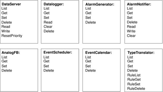
The DataServer application can be used to create, manage, delete, and access data points. The Datalogger can sample and store data-point values in logs and circular buffers. The AlarmGenerator generates alarms – for instance, when certain limits of data-point values are exceeded – while the AlarmNotifier logs alarm conditions, sends notifications via SMTP e-mail, or updates specific data points. The EventScheduler and EventCalendar applications can be used for periodic updates of data points. The TypeTranslator can be utilized to translate values of data points with a specific variable type into a different type.
4.4 A REST Interface for LonWorks
As we have seen in the previous section, a web services interface already exists for LonWorks. However, the new trend in M2M architecture is to use a REST model, where the types of interactions are restricted to only the CRUD1 verbs. This requires a specific design of the representation of the underlying M2M network or device.
Echelon Corporation published a first version of a REST interface for LonWorks in July 2010. In this version 1.0, the “LonBridge Proxy Server REST API” supports the basic CRUD REST interactions, but did not introduce yet a subscribe/notify model: this type of interaction is feasible in a REST architecture but requires both interface sides to act as client and server. Standardized subscribe/notify REST models have been introduced for instance by ETSI TC M2M (refer to Chapter 14 this book): it is expected that ETSI M2M interfaces to LonWorks will also exist in the near future, and introduce the additional interactions and features made possible by the ETSI TC M2M REST architecture.
4.4.1 LonBridge REST Transactions
4.4.2 Requests
The LonBridge API supports the following HTTP request methods:
- GET: retrieve resource data from the LonBridge server;
- POST: create a new resource;
- PUT: update an existing resource managed by the LonBridge proxy server;
- DELETE: delete a resource.
The specifications for each resource describe how the commands are applied.
4.4.3 Responses
Responses include a response body and a status code.
The response body may be formatted as JSON, XML, HTTP, or text. The default is JSON. The response format may be specified as a suffix to the URL – for example GET server/api/devices.xml returns a list of all devices in XML format. The response format may also be specified in the accept header.
The status code is a standard HTTP status code. Typical status codes include the following:
200 – OK (standard response for successful request);
201 – Created (standard response after successfully creating a resource);
400 – Bad Request (request has invalid syntax or cannot be fulfilled);
404 – Not Found (requested resource could not be found but may be available in the future);
500 – Internal Server Error (generic error message when other messages don't apply);
501 – Not Implemented (request not recognized).
4.4.4 LonBridge REST Resources
The various LonBridge REST resources made available by the API are regrouped in seven functional groups addressing the following domains: network, device, device type, connections, groups and measures.
4.4.4.1 Network
These resources allow to access or modify the main LonWorks network parameters.
| Syntax | http://server[:port]/api/network/{resource} [?params] |
| Methods | PUT, GET |
| Resources | Network resources: name, domainId, domainLength, key |
4.4.4.2 Devices
Device resources are used to retrieve and update resources on an individual device or a set of devices. The device ID is the LonBridge device ID, which is the letter “o” followed by an identifier, for example: o0, o1, or o2.
| Syntax | http://server[:port]/api/devices[/{id}[/{resource[=value]}]][?params] |
| Methods | PUT, GET, DELETE |
| Resources | Device resources: name, type, location, scene, active, and data points defined per device type:
Device parameters: startDate (default current date; specified as day[-month[-year]] where month defaults to current month and year defaults to current year), startTime (default current time; 24-h time), interval (default 60 minutes), maxCount (default 100), and deviceType (default all). When a startDate or startTime parameter is specified, up to maxCount records may be returned. Each record includes a timestamp in “year-month-day hour:minute:second” format, for example: 2010-07-05 15:43:10. |
Examples
GET server.com/api/devices – returns list of all devices. The following is an example XML encoded response body:

The following is an example JSON encoded response body:

GET server.com/api/devices?deviceType=“switch” – returns a list of all switch devices. This corresponds to the LonBridge <get TBD /> command.
GET server.com/api/devices/o2 – returns a list of all resources defined for device o2. This corresponds to the LonBridge <o2.get/> command.
GET server.com/api/devices/o2/power – returns the last power-consumption reading for device o2. This corresponds to the LonBridge <o2.get select=“state”/> command.
PUT server.com/api/devices/o2/state – turns on device o2 on or off (the state is sent in the request body). This corresponds to the LonBridge <o2.set state=“on”/> command.
DELETE server.com/api/devices/o2 – deletes device o2. This corresponds to the LonBridge <o2.delete/> command.
4.4.4.3 Device Types
Lists devices by device type.
| Syntax | http://server[:port]/api/{deviceType}/{id}/{resource}[?params] |
| Methods | PUT, GET, DELETE |
| Resources | Device resources: same as for devices.
Device parameters: same as device parameters. |
4.4.4.4 Connections
| Syntax | http://server[:port]/api/connections/{id}/{resource}[?params] |
| Methods | PUT, GET, POST, DELETE |
| Resources | Connection resources: state and setting. |
4.4.4.5 Scenes
| Syntax | http://server[:port]/api/scenes/{id}/{resource}[?params] |
| Methods | GET, POST |
| Resources | Scene resources: state and setting. |
4.4.4.6 Groups
| Syntax | http://server[:port]/api/devices/{id}/groups/{id}/{resource} [?params]
http://server[:port]/api/groups/{id}/{resource}[?params] |
| Methods | PUT, GET, DELETE |
| Resources | Group resources for devices: membership (true or false).
Group resources: state. |
4.4.4.7 Measures
| Syntax | http://server[:port]/api/devices/{id}/groups/{id}/{resource} [?params]
http://server[:port]/api/groups/{id}/{resource}[?params] |
| Methods | GET, POST (define new measure), DELETE (delete measure) |
| Resources | Measure resources are used to retrieve aggregate calculations for current and historical data. |
Examples
GET server.com/api/measures – returns list of all measures.
GET server.com/api/measures/energy – returns aggregate energy usage.
GET server.com/api/measures/energy?startDate=1 – returns up to 100 aggregate energy usage historical values since the first of the month.
GET server.com/api/measures/energy?category=lighting – returns aggregate energy usage for lighting devices.
GET server.com/api/measures/energy?category=lighting&location=“Living Room” – returns aggregate energy usage for lighting devices in the living room location.
GET server.com/api/measures/energy?category=lighting&location=“Living Room”&startDate=1 – returns up to 100 aggregate energy usage historical values for lighting devices in the living room location.
1 Create, read, update, delete.