11
DLMS/COSEM
11.1 DLMS Standardization
11.1.1 The DLMS UA
The Device Language Message Specification1 user association was formed in 1997 by utilities and manufacturers to develop open standards for multiutility (all energy types) meter data exchange, for all application segments. As of 2010 it counts over 180 members, as well as multiple associate member organizations: ESMIG, M-Bus, Euridis.org, Selma, DVGW, PPCEM and the ZigBee Alliance. Over 140 meter types, from over 40 manufacturers, have been certified.
The DLMS UA maintains the specification, is the registration authority for IEC 62 056 (OBIS codes), performs technical support and training, and operates the conformance specification scheme. The DLMS UA is organized in two working groups:
- The Maintenance and Development WG, handling the development of the standard.
- The Final End Users and Developers WG, focused on use cases and gathering feedback from deployment and interop testing, led by French utility EDF.
11.1.2 DLMS/COSEM, the Colored Books
DLMS/COSEM separates the aspects of data modeling, data identification, messaging and transport:
- COSEM, the companion specification for energy metering, specifies the data model, that is, the standard object interfaces, with their attributes and methods. It maintains a registry of object interfaces (OBIS data identification codes). xDLMS messaging is used to access COSEM objects attributes and methods.
- DLMS itself is an application layer protocol that defines abstract object-related services and protocols. Out of the original 22 services defined by DLMS, DLMS/COSEM uses only a subset of 4 messaging services, as well as a few extensions. This profile is named xDLMS.
- DLMS supports multiple transport layers: Twisted pair, power line, IP, and so on.
The DLMS specification is documented in 4 “books”, which can be purchased on DLMS.com:
- The Blue book “COSEM – Identification System and Interface Classes” – DLMS UA 1000-1:2009, Ed. 9.0, 2009-02-09, specifies the data model (COSEM interface classes and OBIS codes for various energy types). The Blue book has been internationally standardized by IEC and CEN.
- The Green book “DLMS/COSEM – Architecture and Protocols” – DLMS UA 1000-2:2009, Ed. 7.0, 2009-12-22, specifies the protocols with DLMS on top, for the various media specific communication profiles. The Green book has been internationally standardized by IEC and CEN.
- The Yellow book specifies conformance test plans for COSEM object model.
- The White book is a glossary of terms.
Together, these books represent over 600 pages of specifications, and the specification is still rapidly expanding. The first implementation of DLMS/COSEM was deployed in 1999. In 2002 the specification was published as IEC and CEN standards. More recently, the standard was adopted by SM-CCG and OPENmeter consortium as the core standard for smart metering. DLMS/COSEM is also published as a standard in China and in India.
11.1.3 DLMS Standardization in IEC
The DLMS-UA work was co-opted by IEC TC13 (International Electrotechnical Commission, Technical Committee 13). The IEC TC13 is in charge of “electrical energy measurement, tariff and load control”. In Europe, the CENELEC TC13 mirrors the IEC TC13. IEC TC 13 endorses the DLMS colored books in their IEC 62 056 series.
The contents of the “Green book” are reflected in the following IEC standard documents:
- IEC 62 056-42: Physical layer services and procedures for connection-oriented asynchronous data exchange;
- IEC 62 056-46: Data-link layer using HDLC protocol;
- IEC 62 056-47: COSEM transport layers for IPv4 networks;
- IEC 62 056-53: COSEM application layer.
The contents of the “Blue book” are reflected in the following standard documents:
- IEC 62 056-61: Object Identification System (OBIS).
- IEC 62 056-62: Interface classes.
The colored books are also reflected in CENELEC standards, for example, EN 13 757 part 1 for the Blue book COSEM interface object model.
11.2 The COSEM Data Model
COSEM is an object model for metering applications that is utility-type and communication-media independent. COSEM uses the client–server paradigm. In the COSEM model, the meter is the server. A COSEM server only models the elements of the meter that are visible externally. COSEM data structures are specified in ASN.1 syntax.
A COSEM server (a physical metering device) is modeled as a set of “logical devices”, hosted in a single physical device. Each logical device models a subset of the functionalities of the physical meter. A logical device is implemented as an application process (AP).
A logical device is composed of a set of COSEM interface objects. Interface objects model various functions of the meter and they are accessible from the client side through the communication interfaces of the meter. Each interface object is a collection of attributes and methods. The structure of objects that have common characteristics is described once for all in an interface class. The interface classes are specified in the DLMS Blue book.
These high-level data model principles are represented in Figure 11.1.
Figure 11.1 DMLS data model overview.

Each physical DLMS device shall provide one “management logical device” which contains the list of logical devices in the physical device (“service access point assignment”) and may contain one or several other logical devices. Each logical device is identified by a unique COSEM logical device name object (LDN), an octet string of up to 16 octets starting with a 3-octet manufacturer identifier. Each logical device also contains an application association object, which contains in its object_list attribute the list of visible COSEM objects in the context of the application association session with a given client (the “association view”).
Note: The DLMS and ZigBee high-level data models are very similar: DLMS Logical Devices are equivalent to ZigBee applications, DLMS interfaces objects are equivalent to ZigBee clusters. The DLMS Blue book is the equivalent of the ZigBee cluster library (ZCL). The fundamental difference is that ZigBee clusters behave as servers or clients, enabling peer to peer communication, while DLMS interface objects are only servers. Another difference is that the Blue book focuses on metering and basic meter related I/O control, while the ZCL scope extends beyond metering.
The object-oriented concept behind COSEM is that any real-world “thing” can be described by some attributes and methods. For the various applications (e.g., energy, billing, load profiles, instant power measurement, I/O control, access control), COSEM maps the “thing” to a COSEM object composed of:
- A set of attributes. Attributes have a meaning, a data type, a value range, and access rights.
- A set of methods (e.g., reset, start).
Similar objects make up an interface class (IC), specified using ASN.1 syntax.
For instance, a meter can offer two registers:
- A register measuring the active energy T1 = 1234 kWh;
- A second register measuring the reactive energy T2 = 0123 kWh.
Both registers are very similar, and can be represented by a name, a value, a unit, and methods for example, reset. They can be modeled by the same interface class, the REGISTER class.
11.3 The Object Identification System (OBIS)
OBIS defines identification codes for commonly used data items in energy metering. The DLMS-UA Blue book and IEC 62 056-61 specify the overall structure of the identification system and the mapping of all data items to their identification codes.
All data items exposed by a meter are uniquely identified by an OBIS code. This is true for measurement data, but the scope of OBIS is wider than measurement data: OBIS codes also cover data used for configuration of metering equipment; or related to the meter status. OBIS codes are defined for all types of utility metering applications: electricity, water, gas and heating.
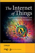
The concept of an OBIS code is based on a hierarchical structure composed of 6 different “value groups”, from A to F (Figure 11.2 and Figure 11.3).
Figure 11.2 Structure of an OBIS code.
Figure 11.3 OBIS code value groups.
- Value group A is for the identification of the energy type. For example, electricity, hot or cold water, gas, heater, cooling are possible energy types.
- Value group B is used to distinguish between several possible inputs in a metering equipment. A data concentrator is a typical example of such equipment.
- Value group C is used for identifying the type of physical quantity, for example, voltage, volume, temperature, power. Value group C items clearly depend on the content of value group A.
- Value groups D and E are used for identifying additional data that can for example be the result of an internal processing by using a specific algorithm applied on data already identified from value groups A to C. It is also used for consortia- or country-specific applications.
- Value group F was originally planned for identifying historical data (billing periods) when needed. If there is no such data then value group E may be used for improving classification.
A part of the range of values in value groups B to F are reserved for manufacturer-specific data.
OBIS codes can be represented by 6 integers in dotted A.B.C.D.E.F format, for example, 1.0.1.8.0.255.
Thousands of OBIS codes have been defined, the complete list is available on the DLMS user association web site (DLMS.com). Interface classes are versioned, and can be extended over time.
In the case of very simple devices, the logical name (LN) referencing method using the OBIS system is not used. A simpler system, using a 13-bit integer for referencing any attribute of a COSEM interface object is used. This simpler system is called short name (SN) referencing. This is useful for ensuring compatibility with the older versions of DLMS.
11.4 The DLMS/COSEM Interface Classes
COSEM defines standard objects, defined by their interface classes (IC), for data storage, access control and management, time and event bound control. Interfaces classes are specified in the DLMS-UA Blue book and in the IEC 62 056-62.
Each interface object is a collection of attributes and methods:
- Attributes represent the characteristics of the object. The first attribute, mandatory, is the “logical name” and its value is an OBIS code or a short name that identifies the measurement category applying to the object instance. For instance, a “register” object with logical name [1 1 1 8 0 255] measures electric total positive active energy, while a “register” object with logical name [1 1 3 8 0 255] measures electric total positive reactive energy. Each interface class definition also allocates an index to each attribute. Each attribute is uniquely identified:
- by the class ID and “logical name” of the object instance to which it belongs, and its index within this instance (LN referencing)
or - by a short 13 bit-integer (SN referencing), for simple devices. Some SN values are reserved for special objects, for example, 0xFA00 for the Association SN.
- by the class ID and “logical name” of the object instance to which it belongs, and its index within this instance (LN referencing)
- Methods: in the object-oriented model of DLMS, external entities can act on the object only through defined methods, for example, for accessing attribute values. For instance, the “reset” method, on a register interface class, sets the current consumption value to the default value. More complex methods are defined, for instance methods that trigger authentication procedures. Within an object instance, methods are identified by their index (LN referencing) or by a short integer (SN referencing).
The set of interface classes represents a tool box that a manufacturer can use when building a meter product, and facilitating interoperability. The model can be extended, new objects only need to be added to the OBIS registry and defined using the appropriate ASN.1 description. Some OBIS code ranges are reserved, for example, for national extensions (specific attributes, interface classes) by using the E164 country code in field C of the interface OBIS code.
Manufacturers may decide not to implement standard interface classes for all objects and use the DLMS manufacturer extension mechanisms. However, when a standard interface class is used, it must be implemented in conformance with the DLMS Blue book.
11.4.1 Data-Storage ICs
- Register (class ID 1): this object contains a value, and an enumerated pointer to a unit.
- Extended register (class ID 3): this object extends the register by providing a time stamp.
- Demand register (class ID 5): extends the register object by storing the current value, as well as maximum and minimum values.
- Register activation (class ID 6): this object specifies at which periods of the day which register is activated.
- Profile generic (class ID 7): this is a generic “spreadsheet-like” object.
- Utility table (class ID 26): this IC encapsulates ANSI C12.19 table data. Each “table” is represented by an instance of this IC, identified by its logical name. The IC attributes are the ANSI Table-Id, the length of the table, and a buffer containing the table data.
- Register table (class ID 61): a simpler version of the profile generic object, which can be used to store multiple similar values.
- Status mapping (class ID 63): while status codes can hardly be standardized, this table maps custom-status codes to utility-specified values.
11.4.2 Association ICs
These objects are specified as gatekeepers to other objects:
- Association SN (class ID 12): list of SN references to objects of a given logical device that are accessible in a given association context with a COSEM client. This object may be present multiple times if a logical device supports multiple application associations.
- Association LN (class ID 15): same as above using LN referencing.
- SAP Assignment (class ID 17): the service access point assignment object contains the list of logical devices within a physical device and their respective service access points.
- Image transfer (class ID 18): this object is used to manage the upload of software images.
- Security setup (class ID 64): contains information on security policies within a particular application association, and methods to set up security keys.
11.4.3 Time- and Event-Bound ICs
- Clock class (class ID 8): the clock object, including timezone and daylight saving data.
- Script table (class ID 9): scripts that can be used for the activation of tariffs, upload of a new firmware, and so on … Scripts are a sequence of method invokes or attribute modifications.
- Schedule object (class ID 10): the “to do list” object, specifying time- or date-driven activities.
- Special days table (class ID 11): list of special days for use with the schedule object or the activity calendar.
- Activity calendar (class ID 20): defines a calendar-based schedule of actions.
- Register monitor (class ID 21): can be used to configure the monitoring of values of several registers and, if certain triggers are met, to execute action scripts.
- Single action schedule (class ID 22): for example, execute firmware.
- Disconnect control (class ID 70): manages a disconnect unit of the meter, for example, a contactor.
- Limiter (class ID 71): triggers an action script when the value attribute of a monitored object crosses a threshold for a certain amount of time.
11.4.4 Communication Setup Channel Objects
Multiple objects have been defined to manage the physical layer parameters and communication setup over these physical layers, for instance:
- IEC local port for IEC 62 056-21 ports;
- IEC HDLC setup;
- TCP-UDP setup;
- IPv4 setup;
- IPv6 setup;
- M-Bus slave.
- M-Bus client (meter acts as master), enable mapping of M-Bus data identifiers (data information block, variable information block) to M-Bus value objects of “extended register” interface class objects.
- M-Bus master port setup, to set EN 13 757-2 interfaces.
11.5 Accessing COSEM Interface Objects
11.5.1 The Application Association Concept
In order to allow the client party to access COSEM interface objects in the server, the DLMS-UA defined the concept of “application association”. This application association is an application-level connection. It is established between a Client AP (application process) and a server AP (one of the logical devices that are modeled in the metering equipment). There is only one Association per logical device. The client AP always initiates the establishment of the association. For very simple devices, one-way communicating devices, and for multicasting and broadcasting pre-established associations are also allowed.
During the association establishment, some contextual data is exchanged and the authentication mechanisms are selected.
After the association establishment, the client AP and the server AP can exchange application data: some of the COSEM interface objects in the server (i.e. one of the logical devices of the metering equipment) become accessible for the client AP. Several data communications services are specified in order to exchange data. Once data exchanges are finished, the association has to be released.
The association establishment is performed by using some basic services of the COSEM application layer that is presented in the next section.
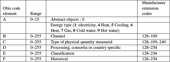
11.5.2 The DLMS/COSEM Communication Framework
The DLMS/COSEM protocol stack contains a metering application, the COSEM application layer and COSEM transport layers. The COSEM application layer is unique for any type of transport layer. Data are exchanged between a server AP and a client AP by using communication profiles (one in the server, one in the client). DLMS-UA defined several communication profiles (implemented in the COSEM transport layer) in the DLMS Green book (IPv4, HDLC, PLC, M-Bus, …).
Note: The DLMS version used in DLMS/COSEM is an extension of the original DLMS specified in IEC 61 334-4-41. This extended version is referred to as xDLMS. However, in the text, we continue to use DLMS.
For a better readability, only the IPv4 transport layer is represented in Figure 11.4.
Figure 11.4 The DLMS/COSEM protocol stack.

The COSEM application layer provides a set of services in order to access to the application interface objects and methods. COSEM application layer services are split into 3 categories:
- application association establishment and release;
- data transfer;
- layer management (for local management, then out of scope of DLMS specifications).
Due to the existence of two different referencing methods (LN and SN) for accessing the meter objects, the COSEM application layer in the client side contains two different sets of services: one for the logical referencing method, the other one for the short name referencing method.
The DLMS application protocol is connection oriented: in the previous section we explained that an application association has to be established between a server AP and a client AP before any communication with COSEM objects can occur. The set of services in charge of application association handling is composed of three services:
- COSEM-OPEN.request;
- COSEM-RELEASE.request;
- COSEM-ABORT.request.
The principle is the following:- COSEM-OPEN.request sets up an application association. During the association establishment, a specific COSEM interface object is created: the “association” object. Among several attributes, this association object contains the list of all visible COSEM interface objects in the context of this association: after Association establishment, the client application process can read the list of visible interface objects, and perform some operations on these objects.
- Application data exchange takes place using DLMS data communication services (refer to the next section for details).
- COSEM-RELEASE.request releases the application association.
for pre-established AAs, OPEN/RELEASE/ABORT requests are not used.
11.5.3 The Data Communication Services of COSEM Application Layer
The data communications services applicable to LN referencing are summarized on the Figure 11.5.
Figure 11.5 DLMS data communication services (LN referencing case).
The set of services is: GET, SET, ACTION and EventNotif.
- The GET service is invoked by the client AP to request the value(s) of one or all attributes of one or more COSEM interface objects from the server AP. For example, the GET service is used for reading the value of an electricity counter. In this case, the class_id is 3 (for register class), and the attribute targeted by the GET service is the “value” attribute.
- The SET service is invoked by the client AP to request the remote server AP to set the value of one or more attributes of a COSEM interface object. For example, the SET service may be used for changing the electricity tariff for a specific period of time.
- The ACTION service is used by the client AP to remotely invoke one or more methods of one or more COSEM interface objects in the remote server AP. The server AP executes the requested ACTION. The reset of a register is a typical example of an invokable method.
- The EventNotification Service: this service is used in order to enable the server AP to send an unsolicited notification of the occurrence of an event to the remote client AP. This notification contains the value of a COSEM interface object attribute. It is an exception to the client–server paradigm. The client AP may explicitly solicit sending an EventNotification message by calling the Trigger_EventNotification_sending service primitive.
In the case of SN referencing, the list of data communication services is different.
- The read service is used to read the value of one or more attributes or to invoke one or more methods of COSEM interface objects.
- The write service is used to write the value of one or more attributes or to invoke one or more methods of COSEM interface objects.
- The UnconfirmedWrite service is used to write the value of one or more attributes or to invoke one or more methods of COSEM interface objects. It is an unconfirmed service.
- The InformationReport service: upon the occurrence of a specific event, the server can inform the client party of the value of one or more COSEM interface object attributes. It is an exception to the client–server paradigm.
The parameters for read/write must include:
- the physical layer MAC address of the meter (this is used by lower layers to establish communication with the meter or concentrator);
- an InvokeID also encoding the priority of the message;
- the interface class OBIS code, for example, REGISTER class;
- the interface class instance (e.g., multiple REGISTER classes may exist on a meter);
- the identifier of the attribute (for get and set), or the identifier of the method (for action).
Referencing may also use short-name mapping of logical name using the interface class mapping table.
The responses include:
- the destination physical layer MAC address;
- an InvokeID also encoding the priority of the message;
- the response data.
Data formats are described in the OBIS profile for the relevant object class. For instance, for the active energy register, attribute 2 is used to store the register using long unsigned encoding, while attribute 3 is an enumerated value mapped to the physical unit.
The lower layers encode the DLMS messaging primitives to PDUs, using A-XDR encoding, a specific version of ASN.1 BER optimized for COSEM data types specified in IEC 61 334-6.
11.6 End-to-End Security in the DLMS/COSEM Approach
DLMS/COSEM provides security features in two different domains:
- Access control security: controls the server data that a given client may access using role-based access rules.
- Security for data transport: provides security during the transport of data from a DLMS/COSEM end-point to another DLMS/COSEM endpoint.
11.6.1 Access Control Security
Access control security is provided as part of the application association establishment procedure.
In order to be able to access server side data, the client has to be authenticated. This is performed during the association establishment. Depending on the capabilities of the meter, the level of the security for the data access is negotiated. DLMS/COSEM provides three different levels of data access security:
- Lowest-level security: in this case there is no security at all. Peer authentication is not needed. This level allows direct access to the data contained in the server.
- Low-level security (LLS).
- High-level security (HLS).
In the LLS security model, the security is ensured via a username/password scheme. The goal is not the authentication of the server. Only the client is authenticated by providing a secret (generally a password) during the application association establishment procedure. The server checks whether the password is correct then the association is considered as established.
The association interface class provides a way to access the password in the server by using the “change_secret” method.
In the HLS security model, a mutual authentication is a prerequisite for application association establishment. Different HLS_Authentication_Mechanisms may be negotiated during the application association establishment (e.g., with different methods for generating a digest, based on MD5, SHA-1, …).
Once the client is authenticated, the list of objects that may be accessed is determined by the server and presented in the AA object_list attribute. This doorkeeper function controls access to associations, registers, profiles, clocks, and so on, using access tables is according to the requester role determined by its identity.
11.6.2 Data-Transport Security
This part of the security scheme provides cryptographic data protection. Ciphering and deciphering is performed by the COSEM application layer on a per-message basis. In order to decide whether ciphering protection is needed, the COSEM AL uses information contained in the security context that was negotiated during the application association establishment. The security context is contained in a security setup object associated to the application association and specifies:
- The level of security to be applied to messages:
- no security;
- all messages have to be authenticated;
- all messages have to be encrypted;
- all messages have to be both authenticated and encrypted.
- The security algorithm to be used: currently the DLMS specifications contain only one security suite, the Galois/counter mode (GCM) with AES-128 symmetric encryption algorithm. Some additional security suites may be added in the future.
- The different security materials and credentials: among them, the master key, the ciphering keys, the authentication keys, the initialization vectors, …
- Security setup object linked to association object, specifying which security services to apply (e.g., encryption).
All meters must have a master key that is pre-established (and communicated via database transfer to the meter controller).
1. The initial name, from French Utility EDF, was “Distribution Line Message Specification”.