9
M-Bus and Wireless M-Bus
9.1 Development of the Standard
The M-Bus standard was the result of collaboration between Dr. Horst Ziegler of the University of Paderborn, a chip maker (Texas Instruments) and a company focused on metering data management (Techem). In 1990 there was no established communication standard for the reading of utility metering devices: such a standard had to be low cost and adapted to battery-powered meters.
The original design uses a simple two-wire serial communication bus, and is documented at http://www.m-bus.com/. One major advantage of the new bus was that all meters and the reading device could be connected to the same wire (which is why it is called a bus).
The link layer used by M-Bus was initially standardized in 1990 as IEC 870-5-1 (Telecontrol Equipment and Systems/Transmission Protocols/Transmission Frame Formats) and IEC 870-5-2 (Link Transmission Procedures, 1992). The first standard to be published related to the M-Bus application layer was EN 1434 in 1997, where parts -2 and -3 define an application layer for a wire communication protocol dedicated to heat meters.
The standardization work is now managed by Cenelec Technical committee TC 294, which generalized the use of M-Bus for any type of meter readout in the EN 13 757 series:
- EN13757-1:2002 Data exchange (DLMS);
- EN13757-2:2004 Physical and link layer (M-Bus);
- EN13757-3:2004 Dedicated application layer (M-Bus);
- EN13757-4:2005 Wireless meter readout (wM-Bus);
- EN13757-5:2007 Relaying (network aspects);
- EN13757-6:2007 Data exchange (local bus).
EN 13 757-2 defines the physical and link layer for the wired bus, while EN 13 757-3 defines the application layer (actual messages). The wireless version of M-Bus is defined in EN 13 757-4.
9.2 M-Bus Architecture
M-Bus was not originally designed for complex multihop networking, and it uses a simplified 4-layer model.
9.2.1 Physical Layer
The two-wire bus interconnects one master and several slaves, using asynchronous half-duplex serial data transmission. Slaves can be powered from the bus.
The nominal voltage of the bus is 36 V. Serial data transmission from the master to slaves uses bus voltage level shifts, while data transmission from the slaves to the master uses a modulation of the slave current consumption (Table 9.1).
Table 9.1 M-Bus wired data transmission, physical layer bit encoding
| Master transmission | Slave transmission | |
| Bit 0 | +36 V | <1.5 mA |
| Bit 1 | +24 V | 11–20 mA |
The quiescent state is always a 1. The start bit of the serial transmission is therefore a “0”, followed by 8 data bits, followed by a parity bit and a stop bit (always 1).
The communication speed can vary between 300 and 9600 bits/s, and up to 250 slaves can be connected over a single twisted pair, which can span up to 1000 m, depending on the number of slaves.
9.2.2 Link Layer
The data link layer is based on IEC 870-5, which defines several frame formats depending on the level of integrity protection required. M-Bus uses frame format class FT 1.2, and defines 4 types of frames (Figure 9.1).
Figure 9.1 M-Bus frames.

The single-character frame is used to acknowledge transmissions.
The short frame has a fixed size.
The long frame has a length field (user data bytes + 3) that is transmitted twice, followed again by the start character.
The control frame is a long frame without user data.
Primary addresses 1 to 250 can be allocated to slaves. Address 0 is reserved for unconfigured slaves. Address 253 is reserved to indicate that the destination address has been set at the network layer. Addresses 254/255 are reserved for managing the local physical layer.
The bits of the control field (C) have a different use depending on the direction of the communication. The FCB bit is used as a one-bit frame counter (used if FCV bit is set). The DFC bit is used by slaves to signal that it can accept no further data. The ACD bit is set when a slave wants to transmit higher-priority data.
The CI field (control information) is part of the application layer.
The link layer defines two transmission services:
- Send/Confirm (SND/CNF): the response is a single-character frame. SND_NKE is used to start or restart a communication (the next master frame will have NCB = 1). SND_UD (optional) is used by the master to send user data to the slave.
- Request/Response (REQ/RSP): REQ_UD2 is used by the master to request data from the slave, and the slave can transfer its data to the slave using RSP_UD.
9.2.3 Network Layer
The M-Bus network is structured into zones, which consists of one or more segments interconnected by repeaters.
The standard provides a way to switch a given slave in a “selected” state, without using or requiring a primary address. In order to achieve this, the master sends a special SND_UD message with CI=52h or 56h to primary address 253 (FDh), which specifies the secondary address of the slave (identification number, manufacturer, version and medium, specified or wildcarded). All slaves receiving this message compare these information elements with their own, the slave that matches, if any, enters “selected” state and sends a single-character response.
Subsequent requests to the selected slave(s) may be sent by SND_UD messages addressed to primary address FDh. Slaves remain in selected state until they receive a new selection command with a nonmatching secondary address.
The selection procedure, because it allows wildcarded parameters for individual address digits composing the secondary address, can also be used by masters for network discovery.
9.2.4 Application Layer
Control information (CI) field values indicate the formatting of the rest of the application data payload. Table 9.2 lists common values of the CI field.
Table 9.2 M-Bus, common CI field values
| 00h-4Fh | Reserved for DLMS applications |
| 54h-58h | |
| 50h | Application reset |
| 51h | Data send (master to slave) |
| 5Ch | Synchronize action |
| 70h | Slave to master: report of application errors |
| 71h | Slave to master: report of alarms |
| 72h | Slave to master: 12-byte header followed by variable format data |
| 78h | Slave to master: variable data format response without header |
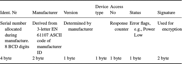
Example user data formatting for CI=72h:
Table 9.3 Application data header example

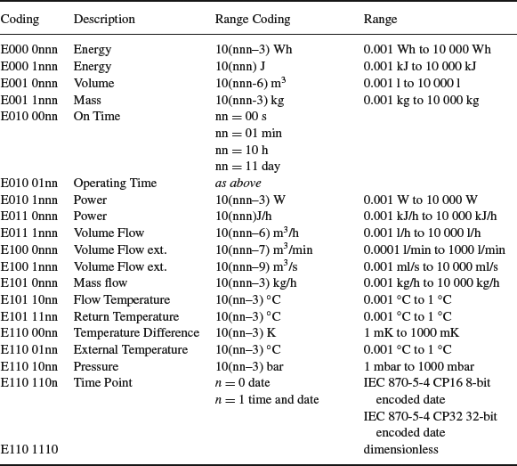
Table 9.4 M-Bus value information field unit codes

- A 12-byte header shown in Table 9.3.
- Variable data blocks: composed of one or more data records. Each data record is composed of a data record header (DRH), followed by the data itself.
The DRH describes the data:- The data information block (DIB) of the DRH describes the length, type and coding of the data (e.g., 6-digit BCD, variable length 8-bit text string) as well as the storage number of the data concerned (register identifier of the value being read), and whether the value being read is an instant value, minimum value or invalid.
- The value information block (VIB) contains the value of the unit and the multiplier. For instance a value information field of “E000 0nnn” corresponds to an energy measurement in Wh from 0,001 Wh to 10 000 Wh with a multiplier of 10(nnn–3). See Table 9.4 for common unit codes.
9.3 Wireless M-Bus
Wireless M-Bus is specified EN13757-4:2005 (wireless meter readout) and uses the 868 MHz frequency, a lower frequency (169 MHz) enabling better penetration within buildings is being standardized as well (prEN13757-4:2011 Mode N). The application messages are specified in EN 13 757-3 as for the wired M-Bus.
The wireless M-Bus specification defines communications between a “meter” device and a “other” device, which usually corresponds to a data concentrator.
Wireless M-Bus uses the 3-layer IEC model, outlined in Figure 9.2.
Figure 9.2 The wireless M-Bus protocol layers, details of the link layer.

9.3.1 Physical Layer
The physical layer is described by EN 13 757-4 “Communication system for meters and remote reading of meters, Part 4: Wireless meter readout, Radio meter reading for operation in the 868 to 870 MHz SRD band”.
Several data transmission modes have been defined on the 868 MHz license free ISM band defined in Europe (Table 9.5): the stationary mode (S-mode), the frequent-transmit mode (T-mode) and the frequent-receive mode (R-mode). The physical and data link layers of the S-mode have been designed jointly with the KNX association, and are identical to KNX-RF (see Chapter 6). More recently, the N-mode, at 169MHZ, has been defined.
All modes have been designed to optimize the battery lifetime, the meter remains in sleep mode except during short transmission periods. Some modes enable bidirectional communication: the meter switches to receive mode for a short period after transmission. Even in bidirectional mode, the “other” side can never initiate a transmission, but needs to wait until the meter wakes up, transmits at least a message, and then switches to receive mode.
Mode T provides the shortest transmission time and the longest battery life for a wireless meter. The battery-life requirements are typically 10 to 20 years.
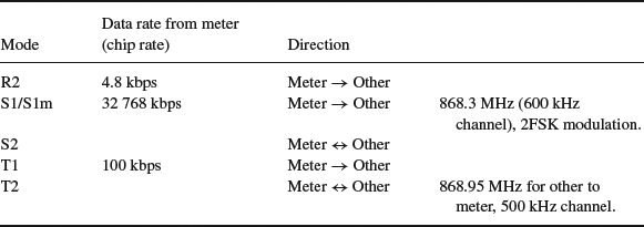
Table 9.5 wM-Bus transmission modes

Wireless M-Bus bit encoding use a higher frequency for encoding chip “1” and a lower frequency for encoding chip “0”. Transmissions begin by a preamble composed of an integer number of “01”, followed by a synchronization word.
For data, the wireless M-Bus specification uses two channel-encoding methods:
- Manchester encoding: data bit “1” is encoded by chip pattern “01”, while bit “0” is encoded by chip pattern “10”. This is a classic encoding that was used to facilitate clock recovery, although with most modern radio chips, it would no longer be required. The resulting data rate is half of the chip rate.
- Three out of six encoding: each byte of data is split in nibbles of 4 bits, each 4-bit nibble is then encoded as 6 chips. As a result, each data byte is encoded in one and a half chip bytes.
The encoded data is then followed by a trailer of two to eight chips.
The various physical layer parameters used for each transmission mode are summarized in Table 9.6.
Table 9.6 Wireless M-Bus physical layer parameters

9.3.2 Data-Link Layer
The data-link layer is defined in IEC 60 870-2-1:1992, Telecontrol equipment and systems, Part 5: Transmission protocols, Section 1: Link transmission procedure, and IEC 60 870-1-1:1990, Telecontrol equipment and systems, Part 5: Transmission protocols, Section 1: Transmission frame formats.
The data-link layer manages framing and CRC generation and detection, provides physical addressing and manages acknowledges (bidirectional modes only).
The wireless M-Bus frame format used in EN 13 757-4:2005 is derived from the frame type 3 (FT3) defined in EC60870-5-2. The frame consists of one or more blocks of data, as illustrated in Figure 9.2. Each block includes a 16-bit CRC field. The first block is a fixed length block of 12 bytes that includes the L-field, C-field, M-field, and A-Field.
- L-Field: in variable packet size mode, the transmission frame format begins by a length indication (L-field), which indicates the number of link-layer payload bytes not including the L, M and A fields, CRC bytes or encoding, from 0 to 255. The L-field itself is encoded using Manchester or 3 out of 6 encoding. Due to the various overheads, the actual maximum value of the L field may be limited by the underlying radio chip packet handler.
- C-Field: the C-field identifies the frame type: SEND, CONFIRM, REQUEST, or RESPOND. For SEND and REQUEST frames, the C-field also indicates whether a CONFIRM or RESPOND is expected.
- M-Field: the manufacturer's 3-letter code (encoded as 3×5 bits by taking the ASCII code and substracting 0x40). Assigned codes are listed at http://www.dlms.com/flag/INDEX.HTM
- A-Field: each device is assigned a unique 6-byte address, assigned by the manufacturer. As in the case of the wired M-Bus, only meters are assigned addresses: the address included in the frame is always the originator address for send and request frames, and the target address for confirm and response data frames. The “other” side remains anonymous.
- CI-Field: the application header specified the application payload type. The possible values are specified in EN13757-4:2005.
- CRC: a 2-byte CRC is added for each 16-byte block, using polynomial x16 + x13 + x12 + x11 + x10 + x8 + x6 + x5 + x2 + 1.
9.3.3 Application Layer
The application layer is defined in EN 13 757-3, Communication system for meters and remote reading of meters, Part 3: Dedicated application layer. It is identical to the application layer of the wired M-Bus, which facilitates bridged M-Bus applications connecting a wired side with a wireless side.
9.3.4 Security
M-Bus data can optionally be encrypted. The original specification used the DES algorithm, while more recent specifications now use the AES 128 algorithm.
When using encryption, the meter is configured with a key, which is shared by the master. Some headers are always sent unencrypted (e.g., the header of Table 9.3), and a portion of the header indicates the encryption method (high byte of the signature field in the example of Table 9.3, for instance DES cipher block chaining). The encrypted data follows.
