
1
IEEE 802.15.4
1.1 The IEEE 802 Committee Family of Protocols
The Institute of Electrical and Electronics Engineers (IEEE) committee 802 defines physical and data link technologies. The IEEE decomposes the OSI link layer into two sublayers:
- The media-access control (MAC) layer, sits immediately on top of the physical layer (PHY), and implements the methods used to access the network, typically the carrier-sense multiple access with collision detection (CSMA/CD) used by Ethernet and the carrier-sense multiple access with collision avoidance (CSMA/CA) used by IEEE wireless protocols.
- The logical link control layer (LLC), which formats the data frames sent over the communication channel through the MAC and PHY layers. IEEE 802.2 defines a frame format that is independent of the underlying MAC and PHY layers, and presents a uniform interface to the upper layers.
Since 1980, IEEE has defined many popular MAC and PHY standards (Figure 1.1 shows only the wireless standards), which all use 802.2 as the LLC layer.
802.15.4 was defined by IEEE 802.15 task group 4/4b (http://ieee802.org/15/pub/ TG4b.html). The standard was first published in 2003, then revised in 2006. The 2006 version introduces improved data rates for the 868 and 900 MHz physical layers (250 kbps, up from 20 and 40 kbps, respectively), and can be downloaded at no charge from the IEEE at http://standards.ieee.org/getieee802/download/802.15.4-2006.pdf
1.2 The Physical Layer
The design of 802.15.4 takes into account the spectrum allocation rules of the United States (FCC CFR 47), Canada (GL 36), Europe (ETSI EN 300 328-1, 328-2, 220-1) and Japan (ARIB STD T66). In the United States, the management and allocation of frequency bands is the responsibility of the Federal Communications Commission (FCC). The FCC has allocated frequencies for industrial scientific and medical (ISM) applications, which do not require a license for all stations emitting less than 1 W. In addition, for low-power applications, the FCC has allocated the Unlicensed National Information Infrastructure (U-NII) band. Figure 1.2 lists the frequencies and maximum transmission power for each band.
Table 1.1 IEEE-defined MAC layers.
| MAC layer | BAND | |
| 802.11 | WiFi | 802.11, 802.11b, 802.11g,
802.11n : ISM 802.11a : U-NII |
| 802.15.1 | Bluetooth | ISM 2.4 GHz |
| 802.15.4 | ZigBee, SLowPAN | ISM 2.4 GHz worldwide
ISM 902–928 MHz USA 868.3 MHz European countries 802.15.4a: 3.1–10.6 GHz |
| 802.16 | Wireless Metropolitan Access Networks Broadband Wireless Access (BWA) WiMax | 802.16 : 10–66 GHz
802.16a: 2–11 GHz 802.16e: 2–11 GHz for fixed/2–6 GHz for mobile |
Figure 1.2 FCC ISM and U-NII bands.
| FCC band | Maximum transmit power | Frequencies |
| Industrial Band | <1W | 902 MHz–928 MHz |
| Scientific Band | <1W | 2.4 GHz–2.48 GHz |
| Medical Band | <1W | 5.725 GHz–5.85 GHz |
| U-NII | <40 mW | 5.15 GHz–5.25 GHz |
| <200 mW | 5.25 GHz–5.35 GHz | |
| <800 mW | 5.725 GHz–5.82 GHz |
IEEE 802.15.4 can use:
- The 2.4 GHz ISM band (S-band) worldwide, providing a data rate of 250 kbps (O-QPSK modulation) and 15 channels (numbered 11–26);
- The 902–928 MHz ISM band (I-band) in the US, providing a data rate of 40 kbps (BPSK modulation), 250 kbps (BPSK+O-QPSK or ASK modulation) or 250 kbps (ASK modulation) and ten channels (numbered 1–10)
- The 868–868.6 MHz frequency band in Europe, providing a data rate of 20 kbps (BPSK modulation), 100 kbps (BPSK+O-QPSK modulation) or 250 kbps (PSSS: BPSK+ASK modulation), and a single channel (numbered 0 for BPSK or O-QPSK modulations, and 1 for ASK modulation).
In practice, most implementations today use the 2.4 GHz frequency band. This may change in the future as the IP500 alliance (www.ip500.de) is trying to promote applications on top of 6LoWPAN and 802.15.4 sub-GHz frequencies and 802.15.4g introduces more sub-GHz physical layer options. More recently, a new physical layer has been designed for ultrawide band (3.1 to 10.6 GHz).
Overview of O-QPSK Modulation at 2.4 GHz
The data to be transmitted is grouped in blocks of 4 bits. Each such block is mapped to one of 16 different symbols. The symbol is then converted to a 32-bit chip sequence (a pseudorandom sequence defined by 802.15.4 for each symbol). The even bits are transmitted by modulating the inphase (I) carrier, and the odd bits are transmitted by modulating the quadrature phase (Q) carrier (Figure 1.3). Each chip is modulated as a half-sine pulse. The transmitted chip rate is 2 Mchip/s, corresponding to a symbol rate 32 times slower, and a user data bitrate of 250 kbps. The sum of the I and Q signals is then transposed to the 2.4 GHz carrier frequency.
Figure 1.3 O-QPSK I and Q components.

802.15.4 uses a 32-bit encoding when it needs to refer to a specific frequency band, modulation, and channel. The first 5 bits encode a page number, and the remaining 27 bits are used as channel number flags within the page. The mapping of page and channel number to the frequency band, modulation and center frequency is shown in Figure 1.4.
Figure 1.4 802.15.4 frequency bands, modulations and channels.

1.2.1 Interferences with Other Technologies
Because the scientific band (2.4–2.48 GHz) is also unlicensed in most countries, this frequency band is used by many wireless networking standards, among which are WiFi (802.11, 802.11b, 802.11g, 802.11n), 802.15.4, and other devices such as cordless phones and microwave ovens.
1.2.1.1 FHSS Wireless Standards
The 802.11 physical layer uses frequency hopping spread spectrum (FHSS) and direct spread spectrum modulation. Bluetooth (802.15.1) uses FHSS in the ISM band.
The FHSS technology divides the ISM band into 79 channels of 1 MHz (Figure 1.5). The FCC requires that a transmitter should not use any channel more than 400 ms at a time (dwell time), and should try to use at least 75 channels (but this may not always be possible if some channels are too noisy).
Figure 1.5 FHSS channels defined by the FCC in the S-Band.
1.2.1.2 DSSS Wireless Standards
802.11b and 802.11g use only direct spread spectrum (DSSS). 11 DSSS channels have been defined, each of 16 MHz bandwidth, with center frequencies of adjacent channels separated by 5 MHz. Only 3 channels do not overlap (outlined in bold font in Figure 1.6): these channels should be used in order to minimize interference issues in adjacent deployments (3 channels are sufficient for a bidirectional deployment, however in tridimensional deployments, for example, in a building, more channels would be required).
Figure 1.6 DSSS channels used by 802.11b.
| DSSS channel | Frequency (GHz) |
| 1 | 2.404–(2.412)–2.420 |
| 2 | 2.409–(2.417)–2.425 |
| 3 | 2.414–(2.422)–2.430 |
| 4 | 2.419–(2.427)–2.435 |
| 5 | 2.424–(2.432)–2.440 |
| 6 | 2.429–(2.437)–2.445 |
| 7 | 2.434–(2.442)–2.450 |
| 8 | 2.439–(2.447)–2.455 |
| 9 | 2.444–(2.452)–2.460 |
| 10 | 2.449–(2.457)–2.465 |
| 11 | 2.456–(2.462)–2.470 |
1.2.2 Choice of a 802.15.4 Communication Channel, Energy Detection, Link Quality Information
In practice, only the 2.4 GHz frequency band is commonly used by the network and applications layers on top of 802.15.4, typically ZigBee and 6LoWPAN. The transmission power is adjustable from a minimum of 0.5 mW (specified in the 802.15.4 standard) to a maximum of 1 W (ISM band maximum). For obvious reasons, on links involving a battery-operated device, the transmission power should be minimized. A transmission power of 1 mW provides a theoretical outdoor range of about 300 m (100 m indoors).
802.15.4 does not use frequency hopping (a technique that consumes much more energy), therefore the choice of the communication channel is important. Interference with FHSS technologies is only sporadic since the FHSS source never stays longer than 400 ms on a given frequency. In order to minimize interference with DSSS systems such as Wi-Fi (802.11b/g) set to operate on the three nonoverlapping channels 1, 6 and 11, it is usually recommended to operate 802.15.4 applications on channels 15, 20, 25 and 26 that fall between Wi-Fi channels 1, 6 and 11.
However, the 802.15.4 physical layer provides an energy detection (ED) feature that enables applications to request an assessment of each channel's energy level. Based on the results, a 802.15.4 network coordinator can make an optimal decision for the selection of a channel.
For each received packet, the 802.15.4 physical layer also provides link quality information (LQI) to the network and application layers (the calculation method for the LQI is proprietary and specific to each vendor). Based on this indication and the number of retransmissions and lost packets, transmitters may decide to use a higher transmission power, and some applications for example, ZigBee Pro provide mechanisms to dynamically change the 802.15.4 channel in case the selected one becomes too jammed, however, such a channel switch should remain exceptional.
1.2.3 Sending a Data Frame
802.15.4 uses carrier-sense multiple access with collision avoidance (CSMA/CA): prior to sending a data frame, higher layers are first required to ask the physical layer to performs a clear channel assessment (CCA). The exact meaning of “channel clear” is configurable: it can correspond to an energy threshold on the channel regardless of the modulation (mode 1), or detection of 802.15.4 modulation (mode 2) or a combination of both (energy above threshold and 802.15.4 modulation: mode 3).
After a random back-off period designed to avoid any synchronization of transmitters, the device checks that the channel is still free and transmits a data frame. Each frame is transmitted using a 30- to 40-bit preamble followed by a start frame delimiter (SFD), and a minimal physical layer header composed only of a 7 bits frame length (Figure 1.7).
Figure 1.7 802.15.4 physical layer frame.
1.3 The Media-Access Control Layer
802.15.4 distinguishes the part of the MAC layer responsible for data transfer (the MAC common part sublayer or MCPS), and the part responsible for management of the MAC layer itself (the Mac layer management entity or MLME).
The MLME contains the configuration and state parameters for the MAC layer, such as the 64-bit IEEE address and 16-bit short address for the node, how many times to retry accessing the network in case of a collision (typically 4 times, maximum 5 times), how long to wait for an acknowledgment (typically 54 symbol duration units, maximum 120), or how many times to resend a packet that has not been acknowledged (0–7).
1.3.1 802.15.4 Reduced Function and Full Function Devices, Coordinators, and the PAN Coordinator
802.15.4 networks are composed of several device types:
- 802.15.4 networks are setup by a PAN coordinator node, sometimes simply called the coordinator. There is a single PAN coordinator for each network identified by its PAN ID. The PAN coordinator is responsible for scanning the network and selecting the optimal RF channel, and for selecting the 16 bits PAN ID (personal area network identifier) for the network. Other 802.15.4 nodes must send an association request for this PAN ID to the PAN coordinator in order to become part of the 802.14.4 network.
- Full Function Devices (FFD), also called coordinators: these devices are capable of relaying messages to other FFDs, including the PAN coordinator. The first coordinator to send a beacon frame becomes the PAN coordinator, then devices join the PAN coordinator as their parent, and among those devices the FFDs also begin to transmit a periodic beacon (if the network uses the beacon-enabled access method, see below), or to respond to beacon requests. At this stage more devices may be able to join the network, using the PAN coordinator or any FFD as their parent.
- Reduced Function Devices (RFD) cannot route messages. Usually their receivers are switched off except during transmission. They can be attached to the network only as leaf nodes.
Two alternative topology models can be used within each network, each with its corresponding data-transfer method:
- The star topology: data transfers are possible only between the PAN coordinator and the devices.
- The peer to peer topology: data transfers can occur between any two devices. However, this is simple only in networks comprising only permanently listening devices. Peer to peer communication between devices that can enter sleep mode requires synchronization, which is not currently addressed by the 802.15.4 standard.
Each network, identified by its PAN ID, is called a cluster. A 802.15.4 network can be formed of multiple clusters (each having its own PAN ID) in a tree configuration: the root PAN coordinator instructs one of the FFD to become the coordinator of an adjacent PAN. Each child PAN coordinator may also instruct a FFD to become a coordinator for another PAN, and so on.
The MAC layer specified by 802.15.4 defines two access control methods for the network:
Figure 1.8 802.15.4 Superframe structure.
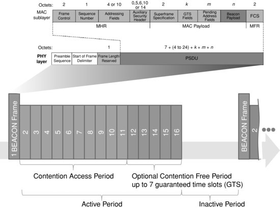
- The beacon-enabled access method (or slotted CSMA/CA). When this mode is selected, the PAN coordinator periodically broadcasts a superframe, composed of a starting and ending beacon frame, 15 time slots, and an optional inactive period during which the coordinator may enter a low-power mode (Figure 1.8). The first time slots define the contention access period (CAP), during which the other nodes should attempt to transmit using CSMA/CA. The last N (N ≤ 7) time slots form the optional contention free period (CFP), for use by nodes requiring deterministic network access or guaranteed bandwidth.
The beacon frame starts by the general MAC layer frame control field (see Figures 1.8 and 1.9), then includes the source PAN ID, a list of addresses for which the coordinator has pending data, and provides superframe settings parameters. Devices willing to send data to a coordinator first listen to the superframe beacon, then synchronize to the superframe and transmit data either during the CAP using CSMA/CA, or during the CFP. Devices for which the coordinator has pending data should request it from the coordinator using a MAC data request command (see Figure 1.10).
When multiple coordinators transmit beacons, the active periods of the super frames should not overlap (a configuration parameter, StartTime, ensures that this is the case). - The nonbeacon-enabled access method (unslotted CSMA/CA). This is the mode used by ZigBee and 6LoWPAN. All nodes access the network using CSMA/CA. The coordinator provides a beacon only when requested by a node, and sets the beaconorder (BO) parameter to 15 to indicate use of the nonbeacon-enabled access method. Nodes (including the coordinator) request a beacon during the active scan procedure, when trying to identify whether networks are located in the vicinity, and what is their PAN ID.
Figure 1.9 802.15.4 MAC layer frame format.
| Bytes | ||
| Frame Control Field | 2 | 000-------------: Beacon frame |
| 001-------------: Data Frame | ||
| 010-------------: Ack Frame | ||
| 011-------------: Command frame | ||
| ---1-------------: Security enabled at MAC layer | ||
| ----1------------: Frame pending | ||
| -----1-----------: Ack request | ||
| ------1----------: PAN ID compression | ||
| (source PAN ID omitted, same as destination) | ||
| -------XXX------: reserved | ||
| ----------XX----:Destination address mode | ||
| 00 : PAN ID and destination not | ||
| present (indirect addressing) | ||
| 01 : reserved | ||
| 10 : short 16-bit addresses | ||
| 11 : extended 64-bit addresses | ||
| ------------XX--:Frame version (00 : 2003, 01 : 2006) | ||
| --------------XX:Source address mode | ||
| Sequence number | 1 | |
| Destination PAN ID | 0 or 2 | |
| Destination address | 0 or 2 or | |
| 8 | ||
| Source PAN ID | 0 or 2 | |
| Source address | 0 or 2 or | |
| 8 | ||
| Auxiliary security | variable | Contains security control, Frame counter, Key identifier fields |
| Payload | variable | |
| FCS | 2 | CRC 16 frame check sequence |
Figure 1.10 802.15.4 command identifiers.
| 01 | Association request |
| 02 | Association response |
| 03 | Disassociation notification |
| 04 | Data request |
| 05 | PAN ID conflict notification |
| 06 | Orphan notification |
| 07 | Beacon request |
| 08 | Coordinator realignment |
| 09 | GTS request |
The devices have no means to know whether the coordinator has pending data for them, and the coordinator cannot simply send the data to devices that are not permanently listening and are not synchronized: therefore, devices should periodically (at an application defined rate), request data from the coordinator.
1.3.2 Association
A node joins the network by sending an association request to the coordinator's address. The association request specifies the PAN ID that the node wishes to join, and a set of capability flags encoded in one octet:
- Alternate PAN: 1 if the device has the capability to become a coordinator
- Device type: 1 for a full function device (FFD), that is, a device capable of becoming a full function device (e.g., it can perform active network scans).
- Power source: 1 if using mains power, 0 when using batteries.
- Receiver on while transceiver is idle: set to 1 if the device is always listening.
- Security capability: 1 if the device supports sending and receiving secure MAC frames.
- Allocation address: set to 1 if the device requests a short address from the coordinator.
In its response, the coordinator assigns a 16-bit short address to the device (or 0xFFFE as a special code meaning that the device can use its 64-bit IEEE MAC address), or specifies the reason for failure (access denied or lack of capacity).
Both the device and the coordinator can issue a disassociation request to end the association.
When a device loses its association with its parent (e.g., it has been moved out of range), it sends orphan notifications (a frame composed of a MAC header, followed by the orphan command code). If it accepts the reassociation, the coordinator should send a realignment frame that contains the PAN ID, coordinator short address, and the device short address. This frame can also be used by the coordinator to indicate a change of PAN ID.
1.3.3 802.15.4 Addresses
1.3.3.1 EUI-64
Each 802.15.4 node is required to have a unique 64-bit address, called the extended unique identifier (EUI-64). In order to ensure global uniqueness, device manufacturers should acquire a 24-bit prefix, the organizationally unique identifier (OUI), and for each device, concatenate a unique 40-bit extension identifier to form the complete EUI-64.
In the OUI, one bit (M) is reserved to indicate the nature of the EUI-64 address (unicast or multicast), and another bit (L) is reserved to indicate whether the address was assigned locally, or is a universal address (using the OUI/extension scheme described above).
1.3.3.2 16-Bit Short Addresses
Since longer addresses increase the packet size, therefore require more transmission time and more energy, devices can also request a 16-bit short address from the PAN controller.
The special 16-bit address FFFF is used as the MAC broadcast address. The MAC layer of all devices will transmit packets addressed to FFFF to the upper layers.
1.3.4 802.15.4 Frame Format
The MAC layer has its own frame format, which is described in Figure 1.9.
The type of data contained in the payload field is determined from the first 3 bits of the frame control field:
- Data frames contain network layer data directly in the payload part of the MAC frame.
- The Ack frame format is specific: it contains only a sequence number and frame check sequence, and omits the address and data fields. At the physical layer, Ack frames are transmitted immediately, without waiting for the normal CSMA/CA clear channel assessment and random delays. This is possible because all other CSMA/CA transmissions begin after a minimal delay, leaving room for any potential Ack.
- The payload for command frames begins with a command identifier (Figure 1.10), followed by a command specific payload.
In its desire to reduce frame sizes to a minimum, 802.15.4 did not include an upper-layer protocol indicator field (such as Ethertype in Ethernet). This now causes problems, since both ZigBee and 6LoWPAN can be such upper layers.
1.3.5 Security
802.15.4 is designed to facilitate the use of symmetric key cryptography in order to provide data confidentiality, data authenticity and replay protection. It is possible to use a specific key for each pair of devices (link key), or a common key for a group of devices. However, the mechanisms used to synchronize and exchange keys are not defined in the standard, and left to the applications.
Figure 1.11 Overview of CCM* security transformations.

Figure 1.12 Security control field codes.
Figure 1.13 Key identifier mode codes.
| Key identifier mode | Description | Key Identifier field length |
| ‘00’ | Key determined implicitly from the originator and recipient of the frame | 0 |
| ‘01’ | Key is determined from the 1-octet Key-index subfield of the Key identifier field, using the MAC layer default Key source | 1 |
| ‘10’ | Key is determined explicitly from the 4-octet Key source subfield, and the 1-octet Key index subfield of the Key identifier field (part of the auxiliary security header) | 5 |
| ‘11’ | Key is determined explicitly from the 8-octet Key source subfield, and the 1-octet Key index subfield of the Key identifier field (part of the auxiliary security header) | 9 |
The degree of frame protection can be adjusted on a frame per frame basis. In addition, secure frames can be routed by devices that do not support security.
1.3.5.1 CCM* Transformations
802.15.4 uses a set of security transformations known as CCM* (extension of CCM defined in ANSI X9.63.2001), which takes as input a string “a” to be authenticated using a hash code and a string “m” to be encrypted, and delivers an output ciphertext comprising both the encrypted form of “m” and the CBC message authentication code (CBC MAC) of “a”. Figure 1.11 shows the transformations employed by CCM*, which uses the AES block cipher algorithm E.
In the case of 802.15.4, L = 2 octets, and the nonce is a 13-octet field composed of the 8-octet address of the device originating the frame, the 4-octet frame counter, and the one-octet security-level code.
1.3.5.2 The Auxiliary Control Header
The required security parameters are contained in the auxiliary control header, which is composed of a security control field (1 octet), a frame counter (4 octets) ensuring protection against replay attacks, and a key identifier field (0/1/5 or 9 octets).
The first 3 bits of the security control field indicate the security mode for this data frame (Figure 1.12), the security mode determines the size of M in the CCM* algorithm (0, 4, 8 or 16 octets), and the data fields included in the “a” and “m” strings used for the computation of the final ciphertext (security attributes). The next 2 bits indicate the key identifier mode (Figure 1.13) and the remaining bits are reserved.
Key Selection
802.15.4 does not handle distribution of keys: the interface between the MAC layer and the key storage is a key lookup function, which provides a lookup string parameter that is used as an index to retrieve the appropriate key.
The lookup material provided depends on the context (see Figure 1.13):
- With implicit key identification (KeyIdMode = “00”), the lookup data is based on the 802.15.4 addresses. The design implies that, in general, the sender indexes its keys according to destinations, and the receiver indexes its keys according to sources.
Addressing mode Sender lookup data (based on destination addressing mode) Receiver lookup data (based on source addressing mode) Implicit Source PAN short or extended address Destination PAN short or extended address Short Destination PAN and destination node address Source PAN and destination node address Long Destination node 802.15.4 8 octet extended address Source node 802.15.4 8 octet extended address
- With explicit key identification, the lookup data is composed of a key source identifier, and a key index. The design implies that the key storage is organized in several groups called key sources (one of which is the macDefaultKeySource). Each key source comprises several keys identified by an index.
The CCM standard specifies that a given key cannot be employed to encrypt more than 261 blocks, therefore the applications using 802.15.4 should not only assign keys, but also change them periodically.
1.4 Uses of 802.15.4
802.15.4 provides all the MAC and PHY level mechanisms required by higher-level protocols to exchange packets securely, and form a network. It is, however, a very constrained protocol
- It does not provide a fragmentation and reassembly mechanism. As the maximum packet size is 127 bytes (MAC layer frame, see Figure 1.7), and the MAC headers and FCS will take between 6 and 19 octets (Figure 1.9), applications will need to be careful when sending unsecured packets larger than 108 bytes. Most applications will require security: the security headers add between 7 and 15 bytes of overhead, and the message authentication code between 0 and 16 octets. In the worst case, 77 bytes only are left to the application.
- Bandwidth is also very limited, and much less than the PHY level bitrate of 250 kbit/s. Packets cannot be sent continuously: the PHY layer needs to wait for Acks, and the CSMA/CA has many timers. After taking into account the PHY layer overheads (preamble, framing: about 5%) and MAC layer overheads (between 15 and 40%), applications have only access to a theoretical maximum of about 50 kbit/s, and only when no other devices compete for network access.
With these limitations in mind, 802.15.4 is clearly targeted at sensor and automation applications. Both ZigBee and 6LoWPAN introduce segmentation mechanisms that overcome the issue of small and hard to predict application payload sizes at the MAC layer. An application like ZigBee takes the approach of optimizing the entire protocol stack, up to the application layer for use over such a constrained network. 6LoWPAN optimizes only the IPv6 layer and the routing protocols, expecting developers to make a reasonable use of bandwidth.
1.5 The Future of 802.15.4: 802.15.4e and 802.15.4g
In the last few years, there has been an increased focus on the use of 802.15.4 for mission critical applications, such as smart utility networks (SUN). As a result, several new requirements emerged:
- The need for more modulation options, notably in the sub-GHz space, which is the preferred band for utilities who need long-range radios and good wireless building penetration.
- The need for additional MAC layer options enabling channel hopping, sampled listening and in general integrate recent technologies improving power consumption, resilience to interference, and reliability.
1.5.1 802.15.4e
Given typical sensor networks performance and memory buffers, it is generally considered that in a 1000-node network:
- Preamble sampling low-power receive technology allows one message per node every 100 s;
- Synchronized receive technology allows one message per node every 33 s;
- Scheduled receive technology allows one message per node every 10 s.
Working group 15.4e was formed in 2008 to define a MAC amendment to 802.15.4:2006, which only supported the last mode, and on a stable carrier frequency. The focus of 802.15.4e was initially on the introduction of time-synchronized channel hopping, but in time the scope expanded to incorporate several new technologies in the 802.15.4 MAC layer. 802.15.4e also corrects issues with the 802.15.4:2006 ACK frame (no addressing information, no security, no payload) and defines a new ACK frame similar to a normal data frame except that it has an “ACK” type. The currently defined data payload includes time-correction information for synchronization purposes1 and optional received quality feedback.
Some of the major new features of 802.15.4e are described below.
1.5.1.1 Coordinated Sampled Listening (CSL)
Sampled listening creates an illusion of “always on” for battery-powered nodes while keeping the idle consumption very low. This technology is commonly used by other technologies, for example, KNX-rf. The idea is that the receiver is switched on periodically (every macCSLperiod, for about 5 ms) but with a very low duty cycle. On the transmission side, this requires senders to use preambles longer than the receiving periodicity of the target, in order to be certain that it will receive the preamble and keep the receiver on for the rest of the packet transmission. For a duty cycle of 0.05% and assuming a 5-ms receive period, the receive periodicity (macCSLperiod) will be 1 s, implying a receive latency of up to 1 s per hop. CSL is the mode of choice if the receive latency needs to be in the order of one second or less.
In 802.15.4e, CSL communication can be used between synchronized nodes (in which case the preamble is much shorter and simply compensates clock drifts), or between unsynchronized nodes in which case a long preamble is used (macCSLMaxPeriod). The latter case occurs mainly for the first communication between nodes and broadcast traffic: the 802.15.4e ACK contains information about the next scheduled receive time of the target node, so the sender can synchronize with the receiver and avoid the long preamble for the next data packet, as illustrated in Figure 1.14.
Figure 1.14 Overview of 802.15.4e CSL mode.
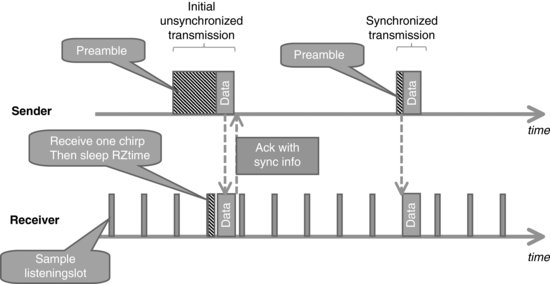
802.15.4e CSL uses a series of microframes (“chirp packets”, a new frame type introduced in 15.4e) as preamble. The microframes are composed of back-to-back 15.4 packets, and include a rendezvous time (RZtime) and optional channel for the actual data transmission: receivers need to decode only one chirp packet to decide whether the coming data frame is to their intention, and if so can decide to go back to sleep until RZtime and wake up again only to receive the data frame.
CSL supports streaming traffic: a frame-pending bit in the 15.4e header instructs the receiver to continue listening for additional packets.
1.5.1.2 Receiver-Initiated Transmission (RIT)
The RIT strategy is a simple power-saving strategy that is employed by many existing wireless technologies: the application layer of the receiving node periodically polls a server in the network for pending data. When using the RIT mode, every macRitPeriod, the receiver broadcasts a datarequest frame and listens for a short amount of time (macRitDataWaitPeriod). The receiver can also be turned on for a brief period after sending data.
The downside of this approach is that the perceived receive latency is higher than in the CSL strategy, and multicast is not supported (must be emulated by multiunicast). The polling typically takes about 10 ms, so in order to achieve an idle duty cycle of 0.05% the macRITPeriod must be 20 s. RIT is adapted to sensor applications, which can tolerate long receive latency.
1.5.1.3 Time-Synchronized Channel Hopping (TSCH)
Channel hopping is a much-awaited feature of 802.15.4:
- It adds frequency diversity to other diversity methods (coding, modulation, retransmission, mesh routing), and will improve the resilience of 802.15.4 networks to transient spectrum pollution.
- In a multimode network, there are situations in which finding a common usable channel across all nodes is challenging. With channel hopping, each node to node link may use a specific set of frequencies.
Channel hopping is supported in the new ACK frame, which contains synchronization information. In an uncoordinated peer to peer network, the channel hopping penalty is only for the initial transmission, as the sender will need to continue to send “chirp packets” on a given send frequency until it becomes aligned with the receiver frequency. After the first ACK has been received, the sender and the receiver are synchronized and the sender will select the sending frequency according to the channel schedule of the receiver. If all joined nodes are in sync, then synchronizing to a single node is enough to be synchronized to the whole network.
The time-synchronized channel hopping (TSCH) mode defined by 802.15.4e defines the operation model of a 802.15.4e network where all nodes are synchronized. The MAC layer of 802.15.4e nodes can be configured with several “slotframes”, a collection of timeslots repeating in time characterized by the number of time slots in the cyclical pattern, the physical layer channel page supported, and a 27-bit channelMap indicating which frequency channels in the channel page are to be used for channel hopping. Each slotframe can be used to configure multiple “links”, each being characterized by the address list of neighboring devices connected to the link (or 0xfff indicating the link is broadcasting to everyone), a slotframeId, the timeslot within the slot frame that will be used by this link, the channel offset of the link,2 the direction (receive, transmit or shared), and whether this link should be reported in advertisement frames. Each network device may participate in one or more slotframes simultaneously, and individual time slots are always aligned across all slotframes.
The FFD nodes in a TSCH mode 802.15.4 network will periodically send advertisement frames that provide the following information: the PAN ID, the channel page supported by the physical layer, the channel map, the frequency-hopping sequence ID (predefined in the standard), the timeslot template ID3 (predefined in the standard), slotframe and link information, and the absolute slot number4 of the timeslot being used for transmission of this advertisement frame. The advertisement frames are broadcast over all links configured to transmit this type of frame.
For PANs supporting beacons, synchronization is performed by receiving and decoding the beacon frames. For nonbeacon-enabled networks, the first nodes joining the network synchronize to the PAN coordinator using advertisement frame synchronization data, then additional nodes may synchronize to existing nodes in the network by processing advertisement frames. For networks using the time division multiple access mode, where precise synchronization of the whole network is essential, a new flag “clockSource” in the FFD state supports the selection of clock sources by 802.15.4e nodes without loops. A keep-alive mechanism is introduced to maintain synchronization.
1.5.2 802.15.4g
IEEE task group 802.15.4g focuses on the PHY requirements for smart utility networks (SUN).
802.15.4g defines 3 PHY modulation options:
- Multiregional frequency shift keying (MR-FSK): providing typically transmission capacity up to 50 kbps. “Multiregional” means that the standard maps a given channel page to a specific FSK modulation (2GFSK, 4GFSK …), frequency and bitrate. The current draft contains multiple variants for each region, implying that generic 802.15.4g radios will have to be extremely flexible.
- Multiregional orthogonal quadrature phase shift keying (O-QPSK): providing typically transmission capacity up to 200 kbps.
- Multiregional orthogonal frequency division multiplexing (OFDM): providing typically transmission capacity up to 500 kbps.
The number of frequency bands also increases to cover most regional markets:- 2400–2483.5 MHz (Worldwide): all PHYs;
- 902–928 MHz (United States): all PHYs;
- 863–870 MHz (Europe): all PHYs;
- 950–956 MHz (Japan): all PHYs;
- 779–787 MHz (China): O-QPSK and OFDM;
- 1427–1518 MHz (United States, Canada): MR-FSK;
- 450–470 MHz, 896–901 MHz, 901–902 MHz, 928–960 MHz (United States): MR-FSK;
- 400–430 MHz (Japan);
- 470–510 MHz (China): all PHYs;
- 922 MHz (Korea): MR-OFDM.
802.15.4g is particularly interesting in Europe, where 802.15.4:2006 allowed a single channel (868.3 MHz). 802.15.4g now offers multiple channels:- from 863.125 to 869.725 MHz in steps of 200 kHz (MR-FSK 200 kHz);
- from 863.225 to 869.625 in steps of 400 kHz (MR-FSK 400 kHz);
- from 868.3 to 869.225 MHz in steps of 400 kHz(O-QPSK);
- from 863.225 to 869.625 MHz in steps of 400 kHz (OFDM).
As the number of potential IEEE wireless standards and modulation options increases, the frequency scanning time would become prohibitively long if a coordinator was to scan all possible channels using all possible modulations. To solve this problem and improve coexistence across IEEE standards, 802.15.4g defines a new coex-beacon format, using a standard modulation method that must be supported by all coordinators (the common signaling mode or CSM defined in 802.15.4g).
1 The value, in units of approximately approximately 0.954 μs, reports the PDU reception time measured as an offset from the scheduled start time of the current timeslot in the acknowledger's time base.
2 Logical channel selection in a link is made by taking (absolute slot number + channel offset) % number of channels. The logical channel is then mapped to a physical channel using predefined conventions.
3 The timeslot template defines timing parameters within each timeslot, e.g TsTxOffset=2120 μs, TsMaxPacket=4256 μs, TsRxAckDelay=800 μs, TsAckWait=400 μs, TsMaxAck=2400 μs.
4 The total number of timeslots that has elapsed since the start of the network.