
5
ModBus
5.1 Introduction
Many protocols have been designed for the needs of industrial automation and metering. These protocols generally use simple query/response models and allow for extremely simple implementations. Many protocols derived from the frame formats defined by IEC 870-5 such as:
- T101 (IEC 870-5-101) that was generated by the IEC TC57 for electric utility communication between master stations and remote terminal units, it is also based on the IEC-870-5-x link layer, using frame format FT 1.2.
- DNP 3.0, a protocol originally designed by Westronic, Inc. that was released into the public domain in 1993, based on the IEC-870-5-x link layer with a few modifications (e.g., use of FT3 frames for asynchronous, rather than synchronous, communication, inclusion of both source and destination addresses).
- M-Bus (see Section 9.3)
- Profibus, a fieldbus initially designed by Siemens and later standardized as IEC 61 158 (“Digital Data Communication for Measurement and control, Fieldbus for use in industrial control systems” for versions DP-V0, DP-V1 and DP-V2) and IEC 61 784 (Communication Profile Family DPF3). The protocols user's association website is http://www.profibus.com/.
Other protocols developed independently into de-facto standards, such as ModBus, a very common protocol that is used in many industrial and HVAC installations.
5.2 ModBus Standardization
ModBus is a trademark of Modicon inc (Schneider Electric group), which also maintains the standard. The ModBus standard specification over a serial line can be found at http://www.modbus.org/docs/Modbus_over_serial_line_V1_02.pdf.
ModBus is an application layer messaging protocol that provides client/server communication between devices connected on different types of buses or networks. Because of its simplicity, ModBus has become one of the de-facto standards for industrial serial-message-based communications since 1979.
ModBus typically runs on top of RS 232, RS 442 point to point or RS 485 point to multipoint links. The ModBus/TCP specification, published in 1999 defines an IP-based link layer for ModBus frames.
ModBus devices communicate using a master-slave model: one device, the master, can initiate transactions (called queries), which can address individual slaves or be broadcast to all slaves. The slaves take action as specified by the query, or return the requested data to the master.
5.3 ModBus Message Framing and Transmission Modes
The transmission mode defines the framing and bit encoding of the messages to be transmitted on the ModBus network. In a given ModBus network, all nodes must use the same mode and serial parameters:
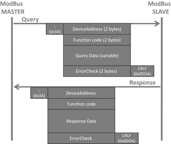
- In the ASCII Transmission Mode, each byte is encoded on the serial link as 2 ASCII characters. Each ASCII character is sent separately as 1 start bit, 7 data bits, zero or one parity bit, one or two stop bits. The message is framed by a starting “:” ASCII byte, and ends with a “CR-LF” byte sequence (see Figure 5.1).
Figure 5.1 ModBus message framing (ASCII mode).
- In the RTU (remote terminal unit) transmission mode, the message is transmitted in a continuous stream. Each 8-bit byte is framed by 1 start bit, 8 data bits, zero or one parity bit, one or two stop bits. The message itself starts after a silent period of at least 3.5 character times.
ModBus Addresses: ModBus messages begin by the target 8-bit address that can take any decimal value between 1 and 247. 0 is used for broadcasts. The address field of the message frame contains two characters in ASCII mode, or 8 bits in RTU Mode. Each query contains the address of a specific slave. When it responds, the slave includes its own address in the message.
ModBus Functions: The function code field contains two characters in ASCII mode, and 8 bits in RTU mode, which can take any decimal value between 1 and 255 and are selected based on the device application profile. Some example functions are listed:
- 0x02: Read Input Status. Parameters: starting register address, and number of consecutive addresses to read. Response data: 1 bit per input read.
- 0x11: Report Slave ID. Parameters: none. Response data: slave ID, run indicator, device specific data.
ModBus Data Field: The data field provides the application level information, as required by the ModBus function. When a given ModBus function requires variable size data, the data field begins with the “byte count” of the data.
5.4 ModBus/TCP
The ModBus/TCP specification can be found at http://www.eecs.umich.edu/∼modbus/documents/Open_ModbusTCP_Standard.doc
ModBus/TCP provides TCP/IP access to the ModBus functionality. Each ModBus Request/response is sent over a TCP connection established between the master and the slave, using well-known port 502. The TCP connection may be reused for several query/response exchanges.
The byte content of the ModBus request and response frames (i.e. without framing start-stop-parity bits specific to the serial physical layer) is simply transported over the TCP connection, in big indian order. The only addition of ModBusTCP is to add a seven-byte message prefix:
ref ref 00 00 00 len unit
The ref bytes are simply copied by the slave from the request, and may be used as a handle by the master. The length information in the message prefix allows proper reassembly of the ModBus message when it has been segmented in several IP packets. The slave address has been renamed “unit identifier” and is contained in unit. The rest of the message conforms to the regular ModBus structure, but the error check fields may be omitted for obvious reasons.