6
KNX
6.1 The Konnex/KNX Association
The Konnex (or KNX) Association was set up in 1999 on the merger between three former European associations promoting intelligent homes and buildings:
- Batibus Club International (BCI France) promoting the Batibus system;
- The European Installation Bus Association (EIBA) promoting the EIB system;
- European Home Systems Association (Holland) promoting the EHS system.
The goal of the KNX Association was to define and offer certification services for the KNX open standard, while offering legacy support and certification cervices for Batibus, EIB1 and EHS. Membership is limited to manufacturers, there are over 200 members from 22 countries as of 2010, including ABB, Agilent, Bosch, Electrolux, Hager, Legrand, Merten, Moeller, Schneider, Siemens and many more leading vendors of home and building automation equipment.
KNX technology is royalty free for KNX members.
6.2 Standardization
In order to standardize the specifications, the KNX association cooperates with CENELEC TC 205. The KNX protocol has become an international standard in Europe as EN 50 090 (media and management procedures), EN 13 321-1 (media) and EN 13 321-2 (CEN, KNXnet/IP).
At an international level, KNX is standardized by ISO and IEC (ISO/IEC 14 543-3). KNX is in prestandard stage in China as GB/Z 20 965.
There are several versions of KNX, which are all backwards compatible. The current version is 2.0 (since August 2009).
The overall specification counts over 6000 pages, divided into 10 volumes.2 Individual specification documents can be purchased from the KNX association. The KonCert group manages KNX certification and testing.
Gateway specifications exist between BACnet (ISO 484 Annex 5 H.5 mapping KNX and BACnet, see also Chapter 3), DALI (lighting control) and KNX.
6.3 KNX Technology Overview
The overall KNX architecture is documented in Vol 3, part 3/1. The KNX architecture is decentralized: nodes can interact with other nodes without the need for a central controller.
The protocol stack uses the OSI model with a null session and presentation layer. It is based on the original work of EIB, which is therefore backward compatible to KNX.
KNX standardizes the protocol, but also the data model (EN 50 090-3-3, KNX volume 3/7) for basic types (integer and float values, percentage) and common device functions such as switching, dimming, blinds control, HVAC and so on …
6.3.1 Physical Layer
The physical layer of KNX is specified in Vol 3, Chapter 3/3/1 of the specifications. KNX can use a variety of physical layers
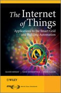
- TP13: Twisted pair (Chapter 3/2/2). TP was the first physical layer that was defined as part of EIB, and is still the dominant physical layer used in KNX deployments. The TP bus provides both power and communication, using inductive coupling (Figure 6.2). A twisted-pair installation is made of lines, each line is composed of up to 4 line segments interconnected by repeaters, and each segment interconnects up to 64 devices. Lines are interconnected by line couplers (LC). The line couplers interconnect to the KNX backbone via a backbone controller (BbC), and the devices that can be accessed via a given BbC are part of the same KNX area (or zone). Line couplers and backbone controllers act as routers, that is, filter the messages that they relay based on the destination address and the domain id (when present). The address space allows up to 15 areas (Figure 6.1), each with 15 lines, and a KNX TP installation can manage a maximum of 61 249 devices.
The physical layer uses a CSMA/CA medium access control using inductive coupling (Figure 6.2), and performs error detection (horizontal or vertical parity checks with acknowledgements (Ack, Nack, busy). The bus provides a 21 to 29 V power supply, and low-power KNX nodes may draw power from the TP line (typically up to 150 mW).
The transmission begins with a start bit (0), followed by a application octet, a parity bit, a stop bit (1) and a mandatory pause (11). The theoretical throughput is 9600 bps. - PL110 Over PLC4 (Chapter 3/2/3). PL110 uses a FSK modulation scheme and was also part of the original EIB specification. Each PLC line can have up to 64 devices. Since PLC is inherently a broadcast open media, the separation of domains (the portion of the KNX network logical topology over which the data signals of one physical layer type propagate) is ensured by a 48-bit domain address, in addition of the zone/line/node Id address (see TP1 for a description of these addresses).
- Over RF (Chapter 3/2/5 defined in 2001). This physical layer uses the 868-870 MHz band (Figure 6.3).
The KNX-rf 1.1 specification was updated in 2010, introducing a “push button” and easy controller mode setup specification, and using a 1% duty cycle on the center frequency 868.3 MHz: this version is called “KNX-rf ready”. It allows bidirectional communication with low duty cycle devices by sending a 4.8-ms preamble for transmissions. Devices are preconfigured with group addresses for multicast communication, and unicast communication uses an “extended group address” composed of the group address of the sender and its serial number.
A further KNX-rf update is expected in 2011 called “KNX-rf multi” that introduces 3 RF “fast channels” and 2 RF “slow channels” (for battery-powered devices and energy-harvesting products) as well as fast acknowledge services. Fast channel 1 would use the existing KNX 1.1 center frequency (868.3 MHz) and a duty cycle of 1%, it is the configuration channel and the default call channel. Fast channel 2 would use a center frequency of 868.95 MHz and a duty cycle of 0-1%, Fast channel 3 (optional, coexisting with slow channel 1) would use a center frequency of 869.85 MHz and a duty cycle up to 100%. Slow channels use a preamble length of 500 ms and duty cycle of 10%. Slow channel 2 will use a center frequency of 869.525 MHz. KNX-rf “multi” products will not be compatible with KNX-rf 1.1. products, but will be compatible with KNX ready products. Because of the preamble, a KNX-rf multireceiver can scan both fast and slow channels (Figure 6.4). - Over IP (Chapter 3/2/6). KNX may use IP as a native communication medium. KNXnet/IP uses binary or XML encoded PDUs to emulate bus communication. KNX/IP defines a tunneling mechanism over IP, using datalink layer binary PDUs.
Figure 6.1 KNX network topology.
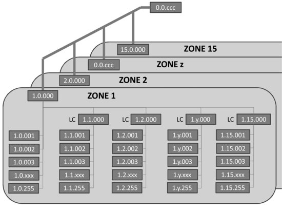
Figure 6.2 KNX TP node, modulation and inductive coupling.

Figure 6.3 Usage of the 863–870 MHz band in Europe.
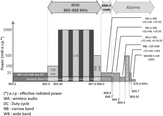
Figure 6.4 KNX-rf multireceiver scanning.
6.3.2 Data Link and Routing Layers, Addressing
The data link layer is specified in Vol 6, Chapter 3/3/2, and the routing layer is specified in Chapter 3/3/3.
KNX nodes exchange telegrams, formatted as in Figure 6.5. Telegrams are transmitted octet by octet on the physical layer. Each telegram is acknowledged by the recipient node after a mandatory pause (equivalent to 11 bits), and retransmitted, if needed, up to 3 times. On TP, a 9 octet command will be transmitted and acknowledged (when unicast) in about 15 ms.
Figure 6.5 KNX telegram format.

Each KNX node has a unique 2 byte address, used mainly for configuration purposes and as the source of telegrams. The source address is encoded on 16 bits as an area identifier (4 bits), a line identifier (4 bits) and a device number (8 bits). The source address appearing in a telegram is always a physical address. This address is configured during the installation process, typically by pressing a key on the device that causes it to enter a signaled state that allows the KNX ETS installation tool to assign an address to the device. Device number 0 is reserved for line couplers and backbone couplers.
The destination address may be a logical group address (bit 17 = 1) or a physical address (bit 17 = 0). The group address may be formatted on 2 levels (4-bit main group ID, 11-bit secondary group ID) or 3 levels (4-bit main group ID, 3-bit auxiliary group ID, 8-bit secondary group ID). The group destination address is the abstraction for a command wire: a KNX switch “connects” to a KNX lamp controller by sending a message to the group that is configured as the lamp controller input, the message acts as a data container for values that the sending nodes wants to share with the receiving node(s). Such group bindings are defined during the configuration of KNX nodes. Special group address 0000 h addresses all KNX nodes.
The KNX installation has a 64 k addressing space. The individual address and all group addresses of a device are stored in the device “address table”.
KNX supports 4 priority levels encoded as specific values of the control bits (see Figure 6.5). In the case of collisions among same priority nodes, the node with the lowest physical address transmits first. On the TP1 physical layer, this priority mechanism derives from the fact that “0” is dominant when a simultaneous 0/1 transmission collision occurs.
The 3-bit routing counter implements a “hop count”: a line coupler decides if a telegram can be transmitted to the other side based on the remaining hop count. The number of hops is normally limited to 6.
An 8-bit parity field secures the KNX telegram, it is based on a vertical parity scheme: bit i of the security field is set to 1 if the octet-wise sum of bits i of the previous telegram data is an even number.
6.3.3 Transport Layer
The KNX transport layer is specified in Volume 3, Chapter 3/4.
The transport layer (TL) provides a connection-oriented peer to peer communication service, providing a connect and disconnect primitive, a TL-acknowledgment, sequence counter and time-out management (typically 6 s for the configuration mode).
The transport layer also removes the source of the message before calling the application layer, and therefore the behavior of actuators never depends on the source of messages.
6.3.4 Application Layer
The KNX application layer is defined in Vol 3, Section 3/3/7. The application layer defines the group objects, and the exchange of group-object values via service requests, for instance “group value write” illustrated in Figure 6.5.
The application layer also defines the “property value write” service, which is used to set values and configuration parameters to KNX device interface objects.
6.3.5 KNX Devices, Functional Blocks and Interworking
Volume 3, part 7 is dedicated to interworking. The overall interworking model is outlined in 3/7/1. Chapter 3/4 defines the application environment, and Chapter 3/4/1 defines the application interface layer, including data representation models for group objects and interface objects. Such as data structures or flags (e.g., transmission allowed, write allowed, data has been written by the bus …).
KNX devices are defined by the functional blocks that they support. A functional block is a logical grouping of inputs, outputs and parameters that are useful to perform a certain function. For instance the “sunblind actuator basic” is one of the functional blocks defined by KNX, which specifies:
- A list of mandatory and optional inputs (Move UpDown, StopStep UpDown, Set Absolute Position blinds Percentage, WindAlarm …).
- A list of mandatory and optional outputs (Info Move UpDown, Current Absolute Position Blinds Length, …).
- A list of mandatory and optional parameters (Reversion Pause time, Move Up/Down time, Preset Slat angle, …).
Inputs, outputs and parameters are specified by their datapoint types (see Section 6.3.5.3, and a specific functional interpretation of the Datapoint values in the specific context of the functional block. Inputs, outputs and parameters may be published as properties or group objects.
KNX volume 6 provides an extensive library of functional blocks (over 146 as of 2011) such as dimming controllers, room temperature controllers, schedulers, system clock, alarm, and so on.
6.3.5.1 Group Objects
The process information of KNX functional blocks (input, output or parameter) may be published as a group object (GO). A group object may be read or written over the bus via dedicated multicast service primitives. The KNX specification of each functional block defines which of the inputs, outputs and parameters may, or must, be published as a group object.
The type of the group object is described by a datapoint (see Section 6.3.6.). A group object that sends its value may be configured with one and only one destination group address, but a group object may listen to several group addresses. The target and monitored group addresses are configured in the KNX device Address Table. All group objects linked to the same group address must be of the same datapoint.
For example, if the on/off group object of a presence sensor (an output) is assigned group address 1/1, and the on/off group object of a light controller (an input) is also assigned group address 1/1, then the presence sensor will control the light controller.
Figure 6.6 KNX interface objects and properties.
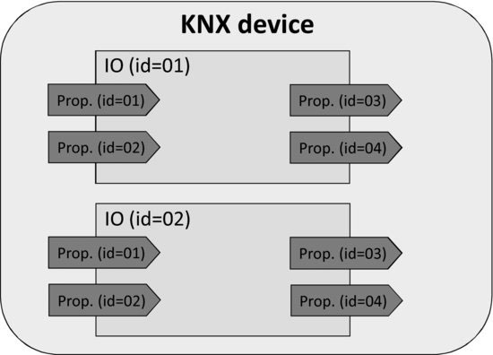
6.3.5.2 Interface Objects
Interface objects (IO) store certain properties of the device, mostly parameters (Figure 6.6). A node can have up to 256 interface objects. The type of each interface object is identified by a 16-bit identifier, the type of property is given by an 8-bit identifier. Chapter 3/7/3 contains the standard identifier tables.
The KNX application layer provides unicast primitives to read or set property values, using messages addressed to the physical address of the device.
The value of a group object can be reflected in the value of a property, in order to make it possible to read or set a property via group communication.
6.3.5.3 KNX Datapoints
Chapter 3/7/2 specifies the datapoint types. KNX provides an extensive library of datapoints (over 350 as of 2011), which are used to express the properties of KNX devices, and parameters of commands sent over the network (see Figure 6.5). Datapoints are defined by:
- Their data type (format and encoding);
- Their dimension (range and unit).
Each datapoint type is identified by a 16-bit main number.16-bit subnumber identifier. The main number identifies the format and encoding, the subnumber identifies the range and unit. Subnumbers are allocated by the KNX association based on the application domain: 0 to 99 for common use range and units, 100 to 499 for HVAC applications, 500 to 599 for load management, 600 to 999 for lighting, 1000 to 1999 for system applications. Subnumbers greater than 60 000 are used by manufacturer-specific extensions.
Figure 6.7 KNX Datapoint field definition symbols.
| A | Character |
| A[n] | String of n characters |
| B | Boolean/Bit set |
| C | Control |
| E | Exponent |
| F | Floating point value |
| M | Mantissa |
| N | eNumeration |
| R | Reserved bit or field |
| S | Sign |
| U | Unsigned value |
| V | 2's Complement signed value |
| Z8 | Standardized Status/Command B8. Encoding as in DPT_StatusGen |
KNX has defined its own syntax to define Datapoints types, with a letter representing the data type of each field (e.g., unsigned value, see Figure 6.7), and a subscript number indicating the number of bits used to encode the data type. For instance, U8 is an unsigned number field encoded over 8 bits. DPT_Date is encoded as r3N5r4N4r1U7, and illustrated on Figure 6.8.
Figure 6.8 DPT_Date KNX datapoint.

For metering applications, KNX has defined a number of datapoints aimed at tunneling M-Bus addresses and metering values, in order to facilitate interworking. See Section 9.3 for more details.
The library of datapoint types may be downloaded from the KNX Association's website for free.
Type information is used mainly at configuration time: it is not transmitted for better performance and to avoid imposing unnecessary restrictions on the combinations of devices.
6.4 Device Configuration
Device configuration uses mainly point to point (unicast) telegrams. There are three options to configure a node:
- In the system mode or “S-mode”, the management configuration tool runs on a PC (using KNX ETS™ software, which stores configuration data as XML schema).
- In easy mode or “E-mode”, several strategies are employed to avoid the use of a PC to configure the network. An embedded “master controller” may be activated to search partner devices, and connects to further devices one by one (identify/discover device). Group bindings may then be configured via a controller menu, or in “push button” mode. In the “push button” mode, links are configured one by one by first activating the actuator (“push-button”), then the sensor to be enrolled.
- Devices may also be preconfigured using a logical tag (extended possibility specified in Volume 10). The devices are preconfigured and use a specific framing format (EFF extended frame format), in additional of the standard format. This mode introduces semantical and geographical zoning tags. Configuration tuning is performed with ETS.
1. EIB is backward compatible to KNX, most devices can be labeled both with the KNX as well as the EIB logo.
2. Vol 1 Primer (deprecated), Vol 2 Cookbook (deprecated), Vol 3 System specifications, Vol 4 Hardware requirements (link to relevant standards, e.g., safety and environmental requirement), Vol 5 Certification manual, Vol 6 profiles, Vol 7 application descriptions (actual functional profiles), Vol 8 conformance testing, Vol 9 Basic and system Components (physical couplers, bus interface modules and couplers), Vol 10 Specific standards (Extended Tag format).
3. There was a TP0 defined, which was deprecated by KNX.
4. There was a PLC 132, which was removed from the specification.