2
Powerline Communication for M2M Applications
2.1 Overview of PLC Technologies
For decades, powerline communication technologies (PLC) have made it possible to use power lines to send and receive data. This “no-new-wire” approach makes PLC one of the best communication technology candidates for the Smart Grid, compared to other wired technologies. On the other hand, as PLC technologies use a media that was not specified for communication, they have faced a number of technical challenges limiting diffusion to niche indoor markets or dedicated ultralow rate applications.
More recently, the booming of modern modulation techniques in integrated silicon made it possible to improve both communication reliability and data rate. Combined with the versatility of emerging protocols such as 6LoWPAN (see the 6LoWPAN chapter), a much larger market is opening for PLC.
Instead of offering here a detailed description of the modulation techniques in use by different vendors/alliances, this can be found for example in [1], this section is more focused on the evolution and comparison of emerging technologies, in the context of the specific requirements of M2M communication.
2.2 PLC Landscape
This section presents an overview of existing powerline technologies and standards. It is not exhaustive and focuses on the most widespread technologies.
2.2.1 The Historical Period (1950–2000)
This first period was driven mainly by utilities for outdoor applications at very low frequencies and with an extremely low rate.
The first experiment started in 1950 for remote street lighting. Basically it was one-way On/Off signaling of 10 kW switches at 10 Hz.
In the mid-1980s research began on the use of electrical distribution grids to support data transmission, in the [5–500 kHz] frequency band, always for one-way communication.
In 1989, the ST7536 was the first monolithic half-duplex synchronous FSK modem suitable for applications according to EN 65 065-1 CENELEC and FCC specifications.
In 1997 the first tests for bidirectional data signal transmission over the electrical distribution network were conducted. A specific research effort was started by Ascom (Switzerland) and Norweb (UK).
2.2.2 After Year 2000: The Maturity of PLC
In the year 2000 the tremendous development of personal computer and home networking triggered more and more demand for high bitrate transmission technologies. As FSK modulation in the CENELEC band suffers strong data-rate limitations, the communication industry, inspired by the boom of ADSL, decided to study the implementation of OFDM (orthogonal frequency-division multiplexing) in the band above 2 MHz.
2.2.2.1 High-Rate Modulations
Homeplug and Homegrid are industrial alliances aiming to publish specifications or white papers on powerline technologies. Since 2000 Homeplug has issued different products standards allowing high data rate communication on existing home electric wires. Usually, these alliances are participating to standard organizations like IEEE and ITU.
Homeplug standards, as all high rate modulation technologies in powerline, use OFDM modulation in the frequency band above 2 MHz.
The typical performance of Homeplug implementations is outlined below:
- HP V1.0: peak PHY rate up to 14 Mb/s.
- HP AV: peak PHY rate up to 200 Mb/s.
- HP AV2 compliant with IEEE 1901: peak PHY rate up to 400–600 Mb/s.
- HP GreenPhy is a low-power profile of IEEE 1901 dedicated to smart grid applications and has a peak PHY rate of 10 Mb/s.
Such impressive performance levels, over such a harsh medium as residential powerline, are only possible through usage of complex signal processing, high power level of PLC emissions and accordingly high power consumption. And still the effective real user data rate usually falls to less than ¼ of the PHY maximum data rate in real-life networks.
Figure 2.1, extracted from the HPAV-White-Paper from HomePlug alliance, shows the complexity involved in this type of modem.
Figure 2.1 HPAV OFDM Transceiver Copyright © 2005, HomePlug® Powerline Alliance, Inc.

2.2.2.2 Low-Rate Modulations
Compared to high-rate OFDM modulation, the complexity of low-rate modems is much lower and a standard DSP can, in most cases, implement the digital processing part of the modem. There are many existing technologies in this field, sometime with a very large installed base.
ISO/IEC 14 908-3 (LonWorks)
This international standard describes an FSK modulation in CENELEC A Band and is used for example in millions of meters in Italy. Refer to Section 4.2 for more details, including the application layer of LonWorks.
IEC 61 334 (S-FSK)
IEC 61 334 is an international standard for low-speed spread shift keying modulation on powerline. It is also known as EN 61 334-5-1:2001. Optional upper layer parts of 61 334 form the DLMS protocol used in metering applications (refer to Section 11.3 for more details on DLMS, including the application layer).
IEC 61 334 is the technology behind G1-PLC, deployed for example, in France as the last-mile communication technology for ERDF (France DSO) first-generation Linky meter.
G3-PLC and PRIME Alliance
G3-PLC and PRIME are two noninteroperable powerline technologies tested by utilities for metering communication. In Europe, both use the CENELEC bands to communicate but they intend also to operate in FCC band up to 500 kHz in the US.
G3-PLC is the powerline communications specification promoted by Maxim and ERDF (French DSO implementing G3 in the second-generation deployment of its “Linky” meter) for smart grid implementations worldwide.
The main specifications of G3 are as follows:
- 10 to 490 kHz operation complies with FCC, CENELEC, and ARIB;
- Coexists with IEC 61 334, IEEE 1901, and ITU G.hn systems;
- Transmission on low- and medium-voltage lines (LV–LV, MV–MV, MV–LV);
- OFDM modulation;
- IEEE 802.15.4-based MAC layer;
- 6LoWPAN adaptation layer supports IPv6 packets;
- AES-128 cryptographic engine;
- Adaptive tone mapping and channel estimation.
In the CENELEC A Band, used by utilities, the OFDM modulation is based on the division of the band into 70 tones. These tones can be modulated in either DBPSK (1 bit per tone), or DQPSK (2 bits per tone).
PRIME is an acronym (PRIME = powerline intelligent metering evolution) for an industry alliance focused on the development of a new open, public and nonproprietary powerline telecom solution for smart grid.
PRIME, created in May 2009, counts more than twenty members at the end of 2010. Principal members are ST Micro, Texas Instruments, ITRON, Landis & Gyr, Iberdrola, Current, ADD and ZIV.
PRIME is based on OFDM multiplexing in CENELEC-A band and is said to reach up to 100 kbps raw data rate. The OFDM signal itself uses 97 (96 data plus one pilot) equally spaced subcarriers with a short cyclic prefix.
Differential modulation schemes are used, together with three possible constellations: DBPSK, DQPSK or D8PSK. Thus, theoretical encoded speeds of around 47 kbps, 94 kbps and 141 kbps (if the cyclic prefix was not considered) could be obtained.
Both G3-PLC and PRIME specifications are the basis of current discussions within IEEE P1901.2 and ITU G.hnem.
Other Low-Rate Modulations
Many other modulations are used for low-rate applications. Most of them use simple modulations like FSK or OOK (X10 for example). Others use different models like spread spectrum or pulse modulation [3].
Table 2.1 shows a comparison between main low-rate technologies in term of standardization, frequency band and modulation.
Table 2.1 Comparison of different powerline technologies


2.3 Powerline Communication: A Constrained Media
Considering the advantages of powerline technology (no additional wires are required, the network already exists in every home), it is clear that this technology should already be deployed in every home for all types of home-automation applications. However, this is not the case.
We will see that reasons of this limited success are due to four key factors.
2.3.1 Powerline is a Difficult Channel
The channel mandated by CENELEC or FCC for communication is one of the noisiest existing. In homes most appliances now switch in the zero-crossing area of the voltage signal, creating strong spikes. Figures 2.2a and b show some examples of this noise.
Figure 2.2 (a) and (b): Spikes and noise around the zero-crossing zone. Courtesy Ytran.

Other categories of noise exist: a precise description can be found in [1].
In addition to strong noise levels, the CENELEC band is also known as a strong fading media.
Figure 2.3 shows an illustration of typical fading profiles in the CENELEC A, B, C, D bands.
Figure 2.3 Example of absorption in the field. Courtesy Maxim.

The notches shown in Figure 2.2 are not stable and could change apparently randomly with time and location.
2.3.2 Regulation Limitations
By definition PLC injects high frequencies in the electric network wires. This injection may induce radio emissions in the HF spectrum and is likely to interfere with existing radio services. For this reason PLC emission and radiation have been regulated from the very beginning.
Basically there is a distinction in term of regulation whether PLC is narrowband or broadband.
- Narrowband services are subject to CENELEC 50 065-1 or FCC Part15 regulations.
- Broadband services regulation is still in discussion in CENELEC (prEN 50 561-1).
For narrowband services, compared to FCC Part15 in the USA, PLC regulation in Europe appears to be more restrictive as only the frequency band less than 148.5 kHz is available for transmission while it is open up to 500 kHz in the US.
EN 50 065-1 allocates the 3–95 kHz frequency band to utilities for metering applications (it is known as the A band) and reserves the 95–125 kHz, 125–140 kHz and 140–148.5 kHz bands (known in early versions of the standard respectively as B, C, D bands) for analog and digital application within homes, commercial or industrial premises and for control of equipment connected to the low-voltage distribution network. Typical examples of B, C, D band applications are street lighting, electric vehicles or home automation.
As EN 50 065-1 conveys no rights to any user to communicate over any part of the electricity network owned by another party, services using narrowband PLC in home are limited to the 95–148.5 kHz band.
This 15-kHz-limited bandwidth severely limits services to extremely low rates applications and is one of the reasons for the limited diffusion of home automation PLC in homes in the CENELEC bands.
2.3.3 Power Consumption
Until recently, power consumption of PLC modems was not seen as a constraint due to the natural access to energy. But the increased awareness of the overall power consumption of IT-related technologies, has now installed power consumption as a major constraint for new PLC technologies:
- Low power is now mandatory for many technologies including powerline systems for smart grid and smart metering deployments.
- In Europe, the “less than ½ Watt” European Directive 2005/32/EC on standby power imposes new paradigms for powerline technologies.
If we look at the numbers: the average consumption of the best IEEE 1901 200 Mb/s powerline modem is around 6 W, while it is close to 4 W for a OFDM CENELEC modem. In a home environment, 4 or 6 W are insignificant compared to a 2 kW air-conditioning unit. But, in the context of M2M with a large number of connected devices, or compared to the consumption of a meter or replacement of a switch it is certainly prohibitive.
It is also prohibitive because the power supply size and heat dissipation are particularly challenging in the context of the form factor required by a meter or a switch.
If we look now at the main contributing factors to the overall PLC technology power consumption, it appears it is roughly balanced between analog subsystems and digital subsystems.
According to Moore's law, digital parts have seen astounding progress in size and performance. But, at the end of the day, having to support increasing data rate, tough channels, sampling frequencies and signal processing are engaged in a never-ending race, thus limiting Moore's Law benefits regarding power consumption.
On the other hand, except for some ultralow-power coupling technologies [3], power consumption of couplers and analog front end (AFE) are limited in their progress by the emission level required by the injection of high-frequency signals in a difficult media.
As a consequence of restrictive regulations and slow progress in power-consumption reduction, some companies are now working on efficient management of sleeping modes and standby states. Radio technologies, like ZigBee or 6LoWPAN, have implemented the same strategy in the past for battery-powered nodes. At first sight, it appears to be an efficient solution for AC powered nodes too … but it isn’t: sleeping modes unfortunately do not solve the power-supply size problem. It is a common [marketing] mistake to mix up overall peak power consumption and energy. A low-energy system, expressed in watt-hour, could need a relatively high peak power, in watt, when operating in “periodic wake-up” mode, and AC power supplies need to be dimensioned according to peak power requirements.
2.3.4 Lossy Network
As shown in Figure 2.4, the PLC link may be subject to as many disturbances as a wireless link, because every electrical device may inject noise and/or absorb the signal. Considering the number of electrical devices in the electrical network of a typical multidwelling unit and their varying electrical behavior that randomly disturbs the communication channel, the routing mechanism over PLC networks has to cope with very lossy links, as well as dynamic loss characteristics. Furthermore, these noise/fading generators create asymmetric links that add routing complexity.
Figure 2.4 Packet delivery ratio (PDR) variation over time on several PLC links. Courtesy Watteco.

Implementation of special purpose routing protocols is now considered as the solution to reach full coverage with a lossy network and difficult channels. The Internet Engineering Task Force (IETF) recognized the need to form a new Working Group to standardize an IPv6-based routing solution for IP smart object networks, which led to the formation of a new Working Group called ROLL “Routing Over Low power and Lossy” networks in 2008.
Here is the charter of ROLL:
Low-power and lossy networks (LLNs) are made up of many embedded devices with limited power, memory, and processing resources. They are interconnected by a variety of links, such as (IEEE 802.15.4, Bluetooth, low-power WiFi, wired or other low power PLC (powerline communication) links. LLNs are transitioning to an end-to-end IP-based solution to avoid the problem of noninteroperable networks interconnected by protocol translation gateways and proxies.
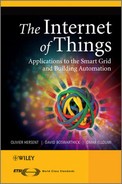
The routing protocol RPL [2] developed in ROLL is the protocol chosen by ZigBee™ IP and 6LoWPAN. The advantage of RPL is that it is independent of the media and then it can be the basis of interoperability between PLC and radio sensors. Interoperability is simply achieved by routing messages from a PLC node to a wireless node. For more details on RPL, refer to the Section 12.4.
Figure 2.5 shows an illustration of this dual PHY sensor network.
Figure 2.5 Wireless nodes and PLC nodes exchange messages through a RPL border router.
The conclusion is that the powerline medium appears to be a very challenging medium, limited by regulation and power consumption and until recently no existing standard really offered a good alternative to wireless for M2M application in home. Fortunately, the recent development of ROLL and the requirement of using IPv6 open the door to new powerline standards interoperable with wireless services using the same routing protocol.
2.3.5 Powerline is a Shared Media and Coexistence is not an Optional Feature
2.3.5.1 Why is Coexistence So Important?
This question of coexistence in PLC has been discussed in many PLC standard organizations. Many articles can be found in the Smart Grid Interoperability Panel (http://collaborate.nist.gov/twiki-sggrid/bin/view/SmartGrid/SGIP).
Powerline cables are a shared medium. They cannot provide links dedicated to a single user and there is no practical way to insulate two neighbors. The signals transmitted within an electrical network can interfere with signals generated within an adjacent house or apartment. It is then likely that these interferences will produce data rate and quality of service drops. The same issues exist in other share media like radio.
For this reason, it is necessary to define mechanisms to limit the harmful interference caused by noninteroperable neighboring devices.
Different mechanisms exist or are proposed today:
- EN 50 065-1 provides a CSMA/CA algorithm and a 132.5-kHz “channel busy” signal for the C band.
- IEEE 1901 and ITU G9972 provide a standard called intersystem protocol (ISP) implementing a TDMA and frequency-division mechanism for a fair access to the shared resource.
- Current discussions in IEEE 1901.2 are also investigating the coexistence between OFDM CENELEC band transmission for metering applications and legacy narrowband services (based on FSK modulation for example).
- prEN50412-4 is a coexistence mechanism in the LRWBS band (2–4 MHz) proposed to CENELEC and based on CSMA/CA in subchannels)
2.3.5.2 Access to the Channel
Low-rate powerline systems have to implement access to channel mechanisms and especially when there is a large number of nodes or when noninteroperable technologies may transmit in the same electrical network. Access to a channel is classically ruled by energy detection in a channel coupled to a CSMA generic mechanism similar to the one described in IEEE 802.15.4.
Compared to the original one, and due to the difference between radio and powerline, some timing constants are different, in particular the backoff period. Basically, the backoff period is the base time a node has to wait before it can transmit after sensing the channel. Compared to 802.15.4 wireless systems, a low-rate PLC modem offers higher latency and lower data rates, however the backoff period has to be chosen short enough (1 ms for example) to allow a sufficient responsiveness for the latency requirements of home-automation applications like switching.
In order to evaluate the impact of data rate and the number of nodes versus average access time, simulations have been carried out with different situations:
- Number of sensors from 5 to 30. All sensors are independent and try randomly to access the network.
- The number of tries/minute is presented vertically.
- A maximum of fail/success rate of 3 is supposed.
- There are no propagation effects and the channel is perfect (best case).
The parameters are:
- backoff period = 1 ms;
- frame size varies randomly from 16 bytes to 128 bytes;
- a failed transmission occurs when the total backoff time > 100 ms (typical minimum latency for home automation HMI).
Figure 2.6 shows that the network supports 20 nodes communicating 400 ms every minute, provided the data rate is a least 100 kb/s.
Figure 2.6 Simulations of the impact of number of nodes on access time. Courtesy Watteco.

With a lower data rate, on average every node will retry more than 3 times to access the channel.
Meters transmitting through a powerline modem in the CENELEC band might be impacted by the results of these simulations. For example in a multidwelling situation it is likely that more than 30 nodes might be within reach of the meters. If a high activity level in homes is required (real-time display of the consumption, thermal regulation …) the 30 nodes could saturate the channel and the latency of the communication between the meter and substations could increase.
Prioritizing meter communication and increasing data rate can minimize this effect but still not cancel it.
Another solution is to use different frequency bands in the home and for metering. For example, the CENELEC band for metering and the LRWBS band (2–4 MHz) for home automation.
2.4 The Ideal PLC System for M2M
PLC combined with recent IPv6 developments could lead to a new standard for wired communication in homes. Recently, in the context of European Mandate 441 for metering applications and home automation, ETSI PLT has defined the requirements of this new standard.
What are the main requirements of this new PLC M2M standard?
- Openness and availability;
- Range;
- Energy consumption;
- Data rate;
- Robustness;
- EMC regulatory compliance;
- Coexistence with other PLC technologies;
- Security;
- Latency;
- Interoperability with M2M wireless services.
2.4.1 Openness and Availability
Open standards, compared to proprietary developments, are accelerating factors for the dissemination and the success of any mass-market technology. Standard openness encourages interoperability, stimulates multisourcing and low-cost policies. The use of available standards, when adaptation to in-home PLC automation is possible, is a tremendous factor of stability and interoperability between existing mature technologies and new emerging ones.
- Home automation standards must use existing, available and internationally recognized PHY, MAC and DLL technologies. Examples are: IEEE 802.15.4, 6LoWPAN, IPv6, RPL …
2.4.2 Range
Range (or coverage) is one of the most important requirements in PLC. It is very challenging because of the extreme harshness of the medium. multidwelling units (MDU) where multiphases networks can exceed an internode distance of 100 m are probably the worst-case situation in terms of range performance.
- The standard should be able to cover all outlets of the home. Routing protocols like RPL can be used to ensure full coverage if needed.
2.4.3 Power Consumption
Power consumption is a very sensitive parameter for home automation applications.
- The standard must enable products to comply with local low power regulations like Directive 2005/32/EC on energy consumption in standby mode in Europe or Energy Star in the US.
- The standard must enable products with low power consumption in relation to the savings users may request for energy-efficiency products.
- The power consumption of a powerline node must be comparable to the power consumption of a wireless node.
2.4.4 Data Rate
Data rate is not a critical requirement per se for home automation applications. A data rate of 10 kb/s is, in most cases, enough to cover in-home lighting or switching applications. However, factors like routing protocols, security, access to media mechanisms in a home with dozen of nodes will probably increase communication stream and payload.
For that reason, it is critical not to limit the standard data rate to 10 kb/s. On the other hand, high-rate PLC systems (>1 Mb/s) are not a good compromise for evident reasons of power consumption. 100 kb/s appears to be a good compromise.
- The standard must provide a nominal rate of 100 kb/s in field installations.
- In the case of very noisy channels, the standard should support variable data rates to keep reliable links.
2.4.5 Robustness
The home environment can be very challenging for PLC nodes. Harsh channels in homes are due to various physical reasons:
- Low impedance appliances (from 1 ohm to 10s of ohms, pure capacitive loads, etc.);
- Disturbance from common electric devices (chargers, dimmers, switching power supplies, etc. …);
- Absorption from breakers and ground fault circuit interrupter;
- Electrical topology (multiphase wiring, neutral/ground connections, etc.).
In order to offer a good end-user experience:
- The standard must provide close to 100% connectivity in the home.
- The standard may use routing or/and data rate adaptation in order to keep connectivity in harsh environments.
- The standard must support multiphase topologies, optionally with phase couplers. Across the world, different home wiring topologies exist using single phase (France, Spain …), dual phase (US and Japan) or three phases (Germany and Northern countries). Usually, the PLC signal is injected in one phase and natural crosstalk between phases may not always be sufficient. In that case phase couplers ensure reinjection of signal from one phase to the other phases.
2.4.6 EMC Regulatory Compliance
- The standard must comply with local EMC regulations in force in the frequency band in use.
2.4.7 Coexistence
- The standard must implement existing coexistence standards when using frequency bands where other PLC systems are also transmitting.
Coexistence standards already in use by legacy PLC systems are:
- EN 50 065-1 C band: (channel busy signaling at 132.5 kHz);
- ISP mechanism in the 2–30 MHz band (as described in IEEE 1901 or ITU G.9972).
2.4.8 Security
- The standard must provide services to support encryption and secure data services. However, a compromise should be found between security and cost of implementation. Furthermore, plug and play installation may conflict with strong security requirements.
- The security suite must be open and available.
2.4.9 Latency
- The standard must support low-latency communication in conformance with end-user usual expectation in home automation. Usually, a latency of 100 ms is considered as a maximum for home automation applications.
2.4.10 Interoperability with M2M Wireless Services
- The standard must ensure interoperability with 6LoWPAN and other wireless compatible protocol through gateways embedding both nodes and running RPL.
2.5 Conclusion
PLC technologies, after a rather difficult and slow start, are now on track for mainstream deployments triggered by smart grid and home automation investment programs and mandates all over the world.
It is worth noting that new paradigms and business models will deeply influence the specifications of emerging standards. The capacity of the communication channel to support encrypted IPv6 frames, the large number of nodes, low power consumption and interoperability with radio transmission technologies are clearly the next challenges engineers will have to overcome.
References
[1] PowerLine Communications (2010) Theory and Applications for Narrowband and Broadband Communication Over Power Lines, Wiley
[2] RPL: IPv6 Routing Protocol for Low power and Lossy Networks - http://tools.ietf.org/html/draft-ietf-roll-rpl.
[3] IPSO White Paper #6 – “A survey of several low power Link layers for IP Smart Objects” by JP Vasseur, Paul Bertrand, Bernard Aboussouan, Eric Gnoske, Kris Pister, Roland Acra and Allen Huotori.