In this chapter we begin the task of exploring the techniques that can help us visualize quaternions and their properties. Because a quaternion is nothing more than a point on a generalized sphere, the first thing to do is to look at the properties of spheres, starting with simple ones, and work our way up to hyperspheres and quaternions. Additional material extending the treatment in this chapter is presented in Chapter 17 and in Appendix I.
To clearly understand our options for making graphical visualizations of quaternions, we need to begin by examining ways in which points on spheres can be viewed in reduced dimensions. Although the full import will not be apparent until later chapters, we will discover in this section that 3D graphics is luckily just sufficient to make a usable interactive graphics system for looking at individual quaternion points, quaternion curves, and even quaternion surfaces, volumes, and sets of streamlines.
A sphere can, in general, be described as the set of points lying at a constant radius from the origin. The local space in which a bug living on a sphere would move is one dimension lower than the Euclidean space used to describe the constant-radius equation. A sphere is parameterized using the dimension in which a bug would live, and thus for example a circle on a piece of paper in 2D space is a one-sphere (or S1) and a balloon in physical 3D space is a two-sphere (or S2), which denotes the surface of the standard sphere of everyday language. Quaternion geometry is the geometry of the hypersphere, typically referred to as the three-sphere (or S3). Thus, we can work up to understanding quaternion geometry by studying spherical geometry in the following sequence of examples:
Equation | Embedding Dimension | |
|---|---|---|
Circle (S1) | q · q = (q0)2 + (q1)2 = 1 |
|
Sphere (S2) | q · q = (q0)2 + (q1)2 + (q2)2 = 1 |
|
Hypersphere (S3) | q · q = (q0)2 + (q1)2 + (q2)2 + (q3)2 = 1 |
|
In each of these cases, we can use a different version of the same visualization method to perceive the structure of the sphere in its local dimension, a dimension one lower than the embedding dimension.
The Sphere Trick
Our first example of the sphere trick follows from examining a circle, a “ring” in 2D, as shown in Figure 8.1. We shall argue that the horizontal projection (the projection perpendicular to q0) is sufficient to determine the entire unit vector up to the sign of q0, and that a two-mode depiction of this horizontal line resolves that ambiguity nicely. The fundamental algebraic equation of the one-sphere S1 is
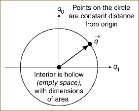
Figure 8.1. The simplest sphere is a circle—a curve of dimension one consisting of the points at a constant distance from the origin and enclosing an empty space (a disk with the dimensions of area).
Our goal is to describe points on the resulting circle using a single 1D line segment. Although our main point is to note that the circle is a curve whose points solve Equation 8.1, Figure 8.1 shows us another important concept; namely, that the interior of the circle, with (q0)2 + (q1)2 < 1, is also a significant component. Depending on how one wants to think of it, one can describe the interior of a circle (and we will generalize this to any sphere) either as an empty space enclosed by the curve or as a space that is “filled up” and thus has dimensions of area. In any event, the points interior to the curve but never part of the curve are an important feature to keep in mind.
Equation 8.1 has only one free parameter, even though we draw it as a locus of points (q0, q1) in 2D. We next examine various ways of choosing the single variable parameterizing the points of S1.
Knowing that the trigonometric functions cosine and sine satisfy Equation 8.1, we could choose to solve the equations as
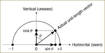
and create a preliminary image (Figure 8.2) showing what would be seen and unseen if we knew only the projection onto the horizontal axis. In this form, the two values of ![]() that solve the equation for each –1 < q1 < +1 emerge automatically from the periodicity of the trigonometric functions.
that solve the equation for each –1 < q1 < +1 emerge automatically from the periodicity of the trigonometric functions.
We recall from our earlier chapter on 2D rotations and complex variables that we can think of a complex variable with unit length as an exponential obeying Euler’s famous identity,
eiθ = cosθ + i sinθ. |
Thus, our circle (as described, for example, by Equation 8.2) can be written as a single unit-magnitude complex variable
z | = | q0 + iq1 |
= | eiθ | |
= | cosθ + i sinθ. |
Recalling the definition of the complex conjugate ![]() , we verify that
, we verify that ![]() .
.
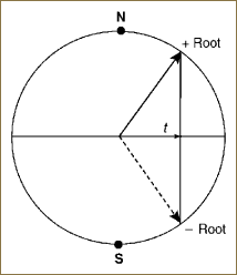
However, we are looking for a way to represent the circle that does not depend on a 2D view. Thus, we examine the alternate parameterization given by the two separate, single-valued roots of Equation 8.1,
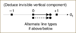
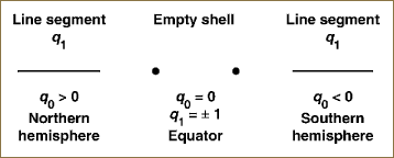
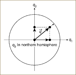
as illustrated by the ambiguous projection shown in Figure 8.3. Taking q1 = t, we thus produce an alternate interpretation of the ambiguity of q0 due to the fact that a quadratic equation has two roots: one in the northern hemisphere and one in the southern hemisphere. Considered only as an intrinsic 1D mathematical object, we can imagine going from the full view in Figure 8.4 to an alternative two-part view (shown in Figure 8.5). We see only two copies of –1 ≤ q1 ≤ 1, corresponding to the plus and minus signs in Equation 8.3, and the equator (the two points q1 = ±1). These two points, which are the degenerate two-point sphere S0 satisfying x2 = 1, effectively sew the two pieces together to enclose the invisible 2D area (seen “sideways” in Figures 8.3 and 8.4). We must now imagine this unseen area as lying between the North and South Poles, and this is what is represented in Figure 8.6.

Figure 8.4. A point on a circle (a unit two-vector) characterized by its projections (q0, q1) onto the two orthogonal coordinate axes. In these two depictions, we show that for the same q1, q0 can be either in the upper (northern) half-space, or in the lower (southern) half-space. We distinguish these by drawing the horizontal projection with either a solid or dashed line. Thus, the horizontal projection and its drawing mode (e.g., solid or dashed) together determine the entire unit vector q without ambiguity.
Let us now focus on the two-part square root representation (Equation 8.3) of the circle. We can see that every value of q1 implies the value of q0 up a sign. Knowing the position of the unit-length mark and the position of q1, we already know what the size of q0 must be. We illustrated this in Figure 8.2, showing also the trigonometric parameterization of the positive root of Equation 8.3 for additional clarity.
From Figure 8.2, we can now imagine tilting the circle until we are looking perpendicular to the q0 axis, finally doing away with q0 altogether. Figure 8.5 shows what happens if we display just q1 and use our knowledge of the fact that ![]() to deduce the missing information. The picture implied by Figure 8.4 is complete if we supply two alternative images corresponding to q0 being above or below the origin. We could code these visually in different colors (as in an interactive computer visualization utility) or with different line styles (as in Figures 8.4 and 8.5).
to deduce the missing information. The picture implied by Figure 8.4 is complete if we supply two alternative images corresponding to q0 being above or below the origin. We could code these visually in different colors (as in an interactive computer visualization utility) or with different line styles (as in Figures 8.4 and 8.5).
Summary: A 1D vector q1 with length varying between –1 and +1, assisted by a two-valued coding or tag, is all we need to watch the behavior of points on a circle, knowing that the missing component always has ![]() .
.
There is one other remarkable fact we should note, and need to remember for the next case. From Figure 8.1, we see that there is a completely empty interior region within the circle. The region, obeying the constraint (q0)2 + (q1)2 < 1, exists and is potentially important. It cannot be seen in Figures 8.5 and 8.6 but must be held in mind.
Each point on S2, the ordinary balloon-like sphere from everyday life in three dimensions, satisfies the equation
Our goal is to describe points on the sphere using a single 2D line segment.
The sphere S2 (described by Equation 8.4) has two free parameters that describe, for example, the latitude and longitude of the spherical surface as 3D points. S2 can be parameterized by two variables in several ways, but it cannot be described in terms of complex variables as we did for S1. As in the case of the circle S1, there is an “interior” of S2, the set of points for which (q0)2 + (q1)2 + (q2)2 < 1 that can either be thought of as the space hollowed out inside S2 or more appropriately as a solid ball filling the portion of the 3D space enclosed by S2. In mathematical language this is referred to as a three-ball, denoted by B3. S2 is the boundary of this object—the skin you would peel off the surface of the solid ball.
Knowing the polar form of a 3D unit vector, we can easily find trigonometric functions satisfying Equation 8.4.
q0 = cosθ,
q2 = sinθ sin φ.
This polar form produces graphic representation shown in Figure 8.7, as well as the projection to 2D shown in Figure 8.8. The 2D projected vectors are modulated simply by sinθ, and thus the value of q0 = cosθ is known up to a sign and we can, for example, draw the vector as a solid line for the northern hemisphere and as a dashed line for the southern.
As before, we can easily write down an alternate parameterization given by the two single-valued roots of Equation 8.4.
We thus produce yet another formulation of the ambiguity of q0 due to the fact that a quadratic equation has two roots. Note that q0 = 0 at the equator, where
(q1)2 + (q2)2 = 1. |
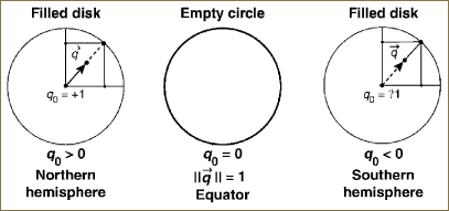
During a continuous motion from the northern hemisphere to the southern hemisphere, the projected vector approaches the equator from the north (where q0 > 0), touches it at q0 = 0, and then reverses apparent direction in the projection as it crosses into the southern hemisphere (where q0 < 0).
In summary, a 2D vector q = (q1, q2) with length varying between 0 and +1, assisted by a two-valued coding or tag, is all we need to watch the behavior of points on a sphere, knowing that the missing component always has ![]() . An interior volume with q · q <1 lies hidden, sandwiched between the disk denoting the projection of the northern hemisphere to the plane and the disk denoting the projection of the southern hemisphere to the plane. The equator of the sphere at q0 = 0 is the circular outer boundary of both disks that joins the northern hemisphere continuously to the southern hemisphere, which we see merged “on top” of each other.
. An interior volume with q · q <1 lies hidden, sandwiched between the disk denoting the projection of the northern hemisphere to the plane and the disk denoting the projection of the southern hemisphere to the plane. The equator of the sphere at q0 = 0 is the circular outer boundary of both disks that joins the northern hemisphere continuously to the southern hemisphere, which we see merged “on top” of each other.
We picture this situation explicitly in Figure 8.9. Again, considered only as an intrinsic 2D mathematical object we can imagine an alternative two-part view of S2, as shown in Figure 8.9. We see only two copies of the filled disk—with (q1)2 + (q2)2 ≤ 1, corresponding to the plus and minus signs in Equation 8.7—and the equator, which is now the circle q0 = 0 or ‖q‖2 = (q1)2 + (q2)2 = 1. This S1 circular curve once again serves to sew together the two filled-in disks surrounding the North and South polar regions to enclose the invisible 3D volume (seen “sideways” in Figure 8.7). We must now imagine this unseen volume as lying between the North and South Poles.
If a four-vector quaternion given by q = (q0, q) obeys the constraint q · q = 1, the locus of these points is the three-sphere S3. The S2, the hollow balloon, had hemispheres that looked like we had filled in the middle of a circle, and each point on the balloon was surrounded by an almost-flat patch of 2D Euclidean space. By analogy, we can understand that each point of S3 is like a little solid cube, an almost-flat patch of 3D Euclidean space, and a hemisphere is constructed by filling in the interior of a balloon. Furthermore, although this is more difficult to see, S3 is also hollow. The hemispheres, which we will study in more detail in a moment, surround an empty region of 4D space; namely, all those 4D points q for which q · q < 1.
The unit quaternion four-vectors, because q · q = 1, lie on the three-sphere S3 itself and do not have four independent degrees of freedom, but can have only three independent components. Just as we did for each of the simpler spheres, we will argue that if we display just three independent components, which we write as q, we can in principle infer the value of ![]() using the sphere projection trick.
using the sphere projection trick.
By the sphere projection trick, q0 is essentially redundant information and can be inferred from the projection and the hemisphere flag. Figure 8.10 shows a solid sphere with a 3D vector q having length less than or equal to unity representing the entire quaternion. At the center (q = 0) we have q0 = +1, and this point—q = (+1, 0, 0, 0)—is the identity quaternion. Moving out to ‖q‖ = 1, we touch the S3 equator, which is itself a two-sphere (S2) surface—the surface at which q0 = 0 and which has no ambiguity. Continuing on a smooth path, we pass through the q0 = 0 equator and “down” into the southern hemisphere, where q0 < 0. When the southern hemisphere flagged-vector q approaches the origin (q = 0) for the second time, we have arrived at q0 = –1, which characterizes the South Pole.

Figure 8.10. A quaternion value displayed as a three-vector q—a vector from the origin (the location of the identity quaternion (1, 0, 0, 0) or q0 = 1) to the point q = (q1, q2, q3) inside a solid ball. The equator ‖q‖ = 1 is the surface of the ordinary sphere S2 enclosing the solid ball.
Quaternion space, as shown in Figure 8.11, thus consists of the following components to be kept in mind during the visualization:
Northern hemisphere: The northern hemisphere is a solid ball of unit radius with the identity quaternion q = (1, 0, 0, 0) appearing at the origin, namely, q = 0.
Southern hemisphere: The solid ball of unit radius with q0 < 0 and the conjugate identity quaternion q = (–1, 0, 0, 0), the South Pole, at the origin where q = 0.
Equator, a two-sphere: The equator is the S2 outer skin of both solid balls, respectively representing the northern hemisphere and the southern hemisphere. The equator is the set of points where q0 = 0 and ‖q‖ = 1, and thus lies exactly halfway between the poles q0 = +1 and q0 = – 1, splitting the entire S3 right down the middle into two identical parts. One can think of the equator as the “stitching” where the two identical halves (the solid balls) are sewn together to make the entire three-sphere.
Four-ball interior: One must imagine an enclosed 4D volume sandwiched between the two solid balls denoting the northern hemisphere and the southern hemisphere (shown in Figure 8.11). This is the interior four-ball with ‖q‖ ≤ 1, whose boundary is in fact the entire S3 at ‖q‖ = 1.

Figure 8.11. The quaternion S3 visualized as two solid 3D balls, the northern and southern hemispheres, together with the equatorial S2 that forms the border exactly between the two, at q0 = 0, or equivalently at ‖q‖ = 1.
One could in principle plot any three quaternion variables or their appropriate linear combinations and infer the unseen coordinate as usual using qunseen = ![]() . One could also implement arbitrary 4D rigid transformations, and project to 3D using the top three rows of an arbitrary interactively adjustable 4 × 4 orthogonal rotation matrix in four Euclidean dimensions.
. One could also implement arbitrary 4D rigid transformations, and project to 3D using the top three rows of an arbitrary interactively adjustable 4 × 4 orthogonal rotation matrix in four Euclidean dimensions.
Any (unit) quaternion is a point on S3 and therefore described by three parameters incorporated in the standard parameterization
where 0 ≤ θ < 4π and where the eigenvector of the rotation matrix (unchanged by the rotation) is a point on the two-sphere S2 representable as
0 ≤ α < 2π | and | 0 ≤ β ≤ π. |
An informative visualization of quaternions can be constructed by examining their properties carefully. If we simply make a 3D display of the vector part of the quaternion, ![]() , we see that the scalar element of the quaternion is redundant because for each θ,
, we see that the scalar element of the quaternion is redundant because for each θ,
That is, q0 is just the implicitly known height of the 4D unit vector in the unseen projection direction, as illustrated in Figure 8.12a. In Figure 8.12b, we schematize the mental model of metric distance required to complete the interpretation of the visualization. If we imagine dividing the arc of the semicircle shown in Figure 8.12a into equal angular segments, the arc lengths are all the same distance apart in spherical coordinates. Projected onto the q plane, however, the projected spacing is nonuniformly scaled by a factor of sinθ. Thus, to keep our vision of distance consistent we imagine the space to be like 3D graph paper with concentric spheres drawn at equal distances in the special scale space. Such a 3D graph paper representation would look like that shown in Figure 8.12b. For small 3D radii, distances are essentially Euclidean near the 3D origin; they are magnified as the radius approaches unity to make the marked spheres equidistant in conceptual space.

Figure 8.12. (a) Illustration of how the q0 = cos(θ/2) part of a quaternion is “known” if we have a 3D image of the vector part ![]() of the quaternion. (b) Schematic representation of the concentric-sphere uniform distance scales needed to form a mental model of the metric distances in quaternion space between two points in the parallel 3D projection. Distances are roughly Euclidean near the origin (q ≈ 0) and equal-length lines appear increasingly compressed as the radius approaches the S2 equator at θ = π, or equivalently ‖q‖ = sin(θ/2) = 1, or q0 = 0.
of the quaternion. (b) Schematic representation of the concentric-sphere uniform distance scales needed to form a mental model of the metric distances in quaternion space between two points in the parallel 3D projection. Distances are roughly Euclidean near the origin (q ≈ 0) and equal-length lines appear increasingly compressed as the radius approaches the S2 equator at θ = π, or equivalently ‖q‖ = sin(θ/2) = 1, or q0 = 0.
If we assume the positive root is always taken for q0, we effectively restrict ourselves to a single hemisphere of S3 and eliminate the twofold redundancy in the correspondence between quaternions and the rotation group. Alternatively, despite the fact that quaternions with both signs of q0 map to the same point in this projection, we can indicate the simultaneous presence of both hemispheres using graphical cues. One possible method is to use saturated colors in the “front” hemisphere and faded colors (suggesting distance) for objects in the “back” hemisphere.
To clarify the terminology, we note that a projected hemisphere for S2 is a filled disk (a two-ball) in the plane, and the full surface of the sphere consists of two such disks joined at the outer circular boundary curve. For S3, we use the word hemisphere to indicate a filled solid two-sphere (technically a three-ball) and imagine the full volume of the three-sphere to consist of two such spherical solids joined on the skin (a two-sphere) of the surface enclosing both.
The family of possible values of Equation 8.8 projects to a double-valued line (actually an edge-on projection of a circle), which is a directed diameter of the unit two-sphere in the direction of ![]() . In a polar projection, this circle becomes a line to infinity through the origin.
. In a polar projection, this circle becomes a line to infinity through the origin.
Any particular 3D rotation is represented twice, because the quaternion circle is parameterized by 0 ≤ θ < 4π. A simple parallel projection thus produces two solid balls on top of each other in the 3D projection—one the analog of the North Pole disk of a two-sphere projected parallel from 3D to a screen, and the other the analog of the South Pole disk of a two-sphere.
