Securing your organization’s internal networks and its use of the Internet is a difficult and challenging task, and that’s a major part of what this chapter will help you with. From its review of the fundamental architecture of the Internet, it will examine the commonly used protocols and services, always with an eye to the security issues involved. You’ll be challenged to switch from your white-hat network defender perspective and take up the point of view of your attackers throughout.
But we as white hats must also grapple with the convergence of communications and computing technologies. People, their devices, and their ways of doing business no longer accept old-fashioned boundaries that used to exist between voice, video, TXT and SMS, data, or a myriad of other computer-enabled information services. This convergence transforms what we trust when we communicate and how we achieve that trust. As SSCPs, we need to know how to gauge the trustworthiness of a particular communications system, keep it operating at the required level of trust, and improve that trustworthiness if that’s what our stakeholders need. Let’s look in more detail at how communications security can be achieved and, based on that, get into the details of securing the network-based elements of our communications systems.
To do this, we’ll need to grow the CIA trinity of earlier chapters—confidentiality, integrity, and availability—into a more comprehensive framework that adds nonrepudiation and authentication (producing the CIANA mnemonic). We’ll also have to address the growing need for network security to achieve the information privacy and safety needs of the organization. This is just one way you’ll start thinking in terms of protocol stacks—as system descriptors, as road maps for diagnosing problems, and as models of the threat and risk landscape.
Understand and Apply Fundamental Concepts of Networking
As with most everything else in our digital world, a set of published standards define the layers upon layers by which we go from physical wires or radio waves to web-based, cloud-hosted services. This layered approach provides inherent scalability, versatility, and adaptability. Complete new sets of functional, physical, or performance requirements—including network and information security—can be added on either by adding new protocols and services at the right layers or by modifying existing ones to fix problems or implement new features. This helps the Internet architecture have a high degree of backward compatibility—not every computer attached to the Internet has to upgrade to a new version of a protocol, or even a wholly new internetworking model, at the same time. (With hundreds of billions of devices currently connected to the Internet, that could be a daunting if not impossible change management challenge.)
Layers of abstraction provide the mental agility that powers the frameworks we use to design, build, use, and secure our computer networks. We take a set of ideas, and we wrap them in a larger, more general, or more abstract concept; we give that concept a catchy name, and then we use that name as part of specifying, building, and testing the processes that use that “black box” along with many others to build up a system that does something purposeful. As a simple example, think about placing a phone call to a family member: you require that the call go to the right person (well, to their phone handset or device); you do not care about the details of how the phone companies make that call happen. You abstract away the details of signaling and switching systems, analog to digital voice (and video) conversion, compression, and all the rest of what makes that bit of infrastructure just plain work when you want it and need it.
As information systems security professionals and as digital natives of one kind or another, we’ve got a number of such stacks of layers of abstraction to deal with when it comes to computer networking.
ISO’s Open Systems Interconnect Reference Model, which goes from the Physical layer to the Application layer
IETF’s Transmission Control Protocol over Internet Protocol (TCP/IP) standard, which goes from the Physical layer to the Transport layer
Design paradigms involving data, control, and management planes, which logically separate our views of these distinctly different but interrelated information flows through and over our networks
Many network and systems professionals use a variety of names to refer to one or both of these protocol stacks, and sometimes even confuse one with the other. For the sake of clarity, it’s best to refer to ISO’s model as the OSI Seven-Layer Reference Model (a proper name which differentiates it from other open systems interconnection models published by ISO); then, use TCP/IP to refer to the IETF’s four-layer protocol standard. Both of these are called protocol stacks because as you build an implementation of them, you build the lowest-level functions first and then layer the next set onto that foundation; similarly, as you execute a function at a higher level, it has to request services from protocols further down the stack at lower levels (all the way down to the physical transmission of the signals themselves).
Many network engineers and technicians may thoroughly understand the TCP/IP model since they use it every day, but they have little or no understanding of the OSI Seven-Layer Reference Model. They often see it as too abstract or too conceptual to have any real utility in the day-to-day world of network administration or network security. Nothing could be further from the truth. As you’ll see, the OSI’s top three levels provide powerful ways for you to think about information systems security, beyond just keeping the networks secure. In fact, many of the most troublesome information security threats that SSCPs must deal with occur at the upper layers of the OSI Seven Layer Reference Model—beyond the scope of what TCP/IP concerns itself with. As an SSCP, you need a solid understanding of how TCP/IP works—how its protocols for device and port addressing and mapping, routing, and delivery, and network management all play together. You will also need an equally thorough understanding of the OSI Seven Layer Reference Model, how it contrasts with TCP/IP, and what happens in its top three layers. Taken together, these two protocols provide the infrastructure of all of our communications and computing systems. Understanding them is the key to understanding why and how networks can be vulnerable—and provides the clues you need to choose the best ways to secure those networks.
That third set of perspectives is also important to keep in mind and use alongside your OSI and TCP/IP thought models. At one level it might seem too abstract to reduce all computer networking to the three broad functions of handling data, controlling its flow, and managing the devices and the networks themselves. Yet this is how the actual devices themselves are designed and built and how the software stacks that implement these protocols are designed, coded, and work with each other. This viewpoint starts internally to every hardware device on our networks, as each device must receive a stream of 1s and 0s and sort them out into groups that convey their meaning as control functions, as management directives, or as data to process. Economy of function dictates that separate logical elements (in hardware and software) take on these logically distinct tasks.
One final set of layers to keep in mind—always—is that every function that makes our networks possible depends upon physical, logical, and administrative actions, processes, and control parameters used by them. That’s four sets of frameworks, protocol stacks, or perspectives, all cross-cutting and interconnected, assisting and interfering with each other at the same time.
Complementary, Not Competing, Frameworks
Both the TCP/IP protocol stack and the OSI Seven Layer Reference Model grew out of efforts in the 1960s and 1970s to continue to evolve and expand both the capabilities of computer networks and their usefulness. Transmission Control Protocol over Internet Protocol (TCP/IP) was developed during the 1970s, based on original ARPANET protocols and a variety of competing (and in some cases conflicting) systems developed in private industry and in other countries. From 1978 to 1992, these ideas were merged together to become the published TCP/IP standard; ARPANET was officially migrated to this standard on January 1, 1993; since this protocol became known as “the Internet protocol,” that date is as good a date to declare as the “birth of the Internet” as any. TCP/IP is defined as consisting of four basic layers. (You’ll learn why that “over” is in the name in a moment.)
The decade of the 1970s also saw two different international organizations, the International Organization for Standardization (ISO) and the International Telegraph and Telephone Consultative Committee (CCITT), working on ways to expand the TCP/IP protocol stack to embrace higher-level functions that business, industry, and government felt were needed. By 1984, this led to the publication of the International Telecommunications Union (ITU, the renamed CCITT) Standard X.200 and ISO Standard 7498.
This new standard had two major components, and here is where some of the confusion among network engineers and IT professionals begins. The first component was the Basic Reference Model, which is an abstract (or conceptual) model of what computer networking is and how it works. This became known as the Open Systems Interconnection (OSI) Reference Model, sometimes known as the seven-layer OSI model or just the seven-layer network model. Since ISO subsequently developed more reference models in the open systems interconnection family, it’s preferable to refer to this one as the OSI Seven Layer Reference Model to avoid confusion. This way, the name represents first the family of models (OSI), then the layers of network protocols used in that family. The other major component was a whole series of highly detailed technical standards.
In many respects, both TCP/IP and the OSI Seven-LayerReference Model largely agree on what happens in the first four layers of their model. But while TCP/IP doesn’t address how things get done beyond its top layer, the OSI Reference Model does. Its three top layers are all dealing with information stored in computers as bits and bytes, representing both the data that needs to be sent over the network and the addressing and control information needed to make that happen. The bottommost layer has to transform computer representations of data and control into the actual signaling needed to transmit and receive across the network. (We’ll look at each layer in greater depth in subsequent sections as we examine their potential vulnerabilities.)
Why Master Both Frameworks?
While it’s true that systems vendors, security professionals, network engineers, systems administrators, and the trade press all talk in terms of both the OSI 7-layer model and the TCP/IP protocol stack, the number-one best reason to know them both is because your enemies know them better!
Amateur attackers and the crews developing the kill chains that APTs will use to take down your systems know these frameworks inside and out. They study them; they model them; they build target and attack systems using them; they customize and reverse-engineer and hack out their own implementations of them.
Don’t let your adversaries keep that monopoly of knowledge.
OSI and TCP/IP Models
All three of these sets of concepts—the two protocol stacks and the set of planes (data, control, and management)—have a number of important operational concepts in common. Let’s first review these before diving into the details of how each protocol stack or the planes use these concepts to help you meet your needs. These common concepts include the following:
Datagrams are groups of individual data symbols, such as bits or bytes, that are treated as one unit by a protocol.
Protocols define the functions to be performed, the interfaces for requesting these functions as services, and the input, output, error, and control interfaces associated with using that protocol. (These will be discussed in detail in the “Commonly Used Ports and Protocols” section.)
Handshakes provide a lower-level coordination and control function; most protocols define a set of handshakes for their use.
Packets and encapsulation are how datagrams are packaged with routing and control information needed by the next layer of the protocol stack so that it can accommodate the requested function or routing.
Addressing, routing, and switching functions provide ways for endpoints and users to identify themselves to the network, direct the flow of information to other endpoints by specifying logical or symbolic addresses, and specify how the network maps these symbolic addresses to specific network hardware and software elements.
Network segmentation provides ways to logically and physically break up a large network into smaller subnetworks, providing some degree of isolation of subnets from each other, in order to better manage, provision, control, and protect the Internet and each subnet.
Uniform resource locators (URLs) provide the symbolic addressing of files (or of content within those files) and the protocols that allow users and endpoints to access those files, information, or services. These resources can be on the Internet, on a local intranet, or even on a single system (such as links to elements of documents in the same directory subtree).
Each of the concepts discussed in the preceding list embodies its own layers of abstraction.
A protocol stack is a document—a set of ideas or design standards. Designers and builders implement the protocol stack into the right set of hardware, software, and procedural tasks (done by people or others). These implementations present the features of the protocol stack as services that can be requested by subjects (people or software tasks).
All computer networking protocol stacks provide well-defined processes for managing and controlling the sending and receiving of data. Both TCP/IP and the OSI Seven-Layer Reference Model refer to groups of data values as a datagram; just what a datagram is depends in large part on what layer of the protocol stack it is making use of in its journey across the network.
Datagrams and Protocol Data Units
First, let’s introduce the concept of a datagram, which is a common term when talking about communications and network protocols. A datagram is the unit of information used by a protocol layer or a function within it. It’s the unit of measure of information in each individual transfer. Each layer of the protocol stacks takes the datagram it receives from the layers above it and repackages it as necessary to achieve the desired results. Sending a message via flashlights (or an Aldiss lamp, for those of the sea services) illustrates the datagram concept:
An on/off flash of the light, or a flash of a different duration, is one bit’s worth of information; the datagrams at the lamp level are bits.
If the message being sent is encoded in Morse code, then that code dictates a sequence of short and long pulses for each datagram that represents a letter, digit, or other symbol.
Higher layers in the protocol would then define sequences of handshakes to verify sender and receiver, indicate what kind of data is about to be sent, and specify how to acknowledge or request retransmission. Each of those sequences might have one or more message in it, and each of those messages would be a datagram at that level of the protocol.
Finally, the captain of one of those two ships dictated a particular message to be sent to the other ship, and that message, captain-to-captain, is itself a datagram.
Note, however, another usage of this word. The User Datagram Protocol (UDP) is an alternate data communications protocol to Transmission Control Protocol, and both of these are at the same level (layer 3, Internetworking) of the TCP/IP stack. And to add to the terminological confusion, the OSI Reference Model (as you’ll see in a moment) uses a protocol data unit (PDU) to refer to the unit of measure of the data sent in a single protocol unit and datagram to UDP. Be careful not to confuse UDP and PDU!
Table 6.1 may help you avoid some of this confusion by placing the OSI and TCP/IP stacks and their datagram naming conventions side by side. We’ll examine each layer in greater detail in a few moments.
HTTP, HTTPS, SMTP, IMAP, SNMP, POP3, FTP, and so on
7. Application
Data
(Outside of TCP/IP model scope)
Data
Characters, MPEG, SSL/TLS, Compression, S/MIME, and so on
6. Presentation
NetBIOS, SAP, Session handshaking connections
5. Session
TCP, UDP
4. Transport
Segment, except UDP Datagram
Transport
Segment
Media layers
IPv4 / IPv6 IP address, ICMP, IPsec, ARP, MPLS, and so on
3. Network
Packet
Network (or Internetworking)
Packet
Ethernet, 802.1, PPP, ATM, Fibre Channel, FDDI, MAC Address
2. Link
Frame
Data Link
Frame
Cables, Connectors, 10BaseT, 802.11x, ISDN, T1, and so on
1. Physical
Symbol
Physical
Bits
Handshakes
In signaling and control systems terms, a handshake is a defined set of message exchanges between two elements that initiates, coordinates, and performs some function or service involving the two elements. It’s a sequence of small, simple communications that we send and receive, such as hello and goodbye, ask and reply, or acknowledge or not-acknowledge, which control and carry out the communications we need. Handshakes are defined in the protocols we agree to use. Let’s look at a simple file transfer to a server that I want to do via File Transfer Protocol (FTP)1 to illustrate this:
I ask my laptop (by interacting with its operating system) to run the file transfer client app.
Now that it’s running, my FTP client app asks the OS to connect to the FTP server.
The FTP server accepts my FTP client’s connection request.
My FTP client requests to upload a file to a designated folder in the directory tree on that server.
The FTP server accepts the request and says “start sending” to my FTP client.
My client sends a chunk of data to the server; the server acknowledges receipt, or it requests a retransmission if it encounters an error.
My client signals the server that the file has been fully uploaded and asks the server to mark the received file as closed, updating its directories to reflect this new file.
My client informs me of successfully completing the upload.
With no more files to transfer, I exit the FTP app.
This sequence of steps is akin to a business process—it’s designed to accomplish a specific logical function, and implicit in its flow are the handshakes that invoke lower-level functions or support services, pass data and control information to and from those services, and detect and handle any errors or exceptions involved in performing those services. Step 2, for example, may have to initiate both a physical and logical connection to the Internet via my laptop’s Wi-Fi device, the Wi-Fi router/modem provided by my Internet service provider (ISP), and the ISP’s connectivity to the Internet itself. Step 2 also has to perform any required connections with the FTP server, which might include authenticating me as a legitimate user, my laptop as an authorized device, and even the IP address or region I’m connecting from as an approved remote login locale. Each of those activities involves multiple sets of handshakes. The physical connections handle the electronic (or electro-optical) signaling that the devices themselves need to communicate with each other. The logical connections are how the right pair of endpoints—the user NIC and the server or other endpoint NIC—get connected with each other, rather than with some other device “out there” in the wilds of the Internet. This happens through address resolution and name resolution, which I’ll cover in more detail in the “Addressing, Routing and Switching Concepts” section.
Packets and Encapsulation
Note in that FTP example earlier how the file I uploaded was broken into a series of chunks, or packets, rather than sent in one contiguous block of data. Each packet is sent across the Internet by itself (wrapped in header and trailer information that identifies the sender, recipient, and other important information). Breaking a large file into packets allows smarter trade-offs between actual throughput rate and error rates and recovery strategies. (Rather than resend the entire file because line noise corrupted one or two bytes, we might need to resend just the one corrupted packet.) However, since sending each packet requires a certain amount of handshake overhead to package, address, route, send, receive, unpack, and acknowledge, the smaller the packet size, the less efficient the overall communications system can be.
Sending a file by breaking it up into packets has an interesting consequence: if each packet has a unique serial number as part of its header, as long as the receiving application can put the packets back together in the proper order, we don’t need to care what order they are sent in or arrive in. If the receiver requested a retransmission of packet number 41, it can still receive and process packet 42, or even several more, while waiting for the sender to retransmit it.
Right away we see a key feature of packet-based communications systems: we have to add information to each packet in order to tell both the recipient and the next layer in the protocol stack what to do with it! In our FTP example earlier, we start by breaking the file up into fixed-length chunks, or packets, of data—but we’ve got to wrap them with data that says where it’s from, where it’s going, and the packet sequence number. That data goes in a header (data preceding the actual segment data itself), and new end-to-end error correcting checksums are put into a new trailer. This creates a new datagram at this level of the protocol stack. That new, longer datagram is given to the first layer of the protocol stack. That layer probably has to do something to it; that means it will encapsulate the datagram it was given by adding another header and trailer. At the receiver, each layer of the protocol unwraps the datagram it receives from the lower layer (by processing the information in its header and trailer, and then removing them) and passes this shorter datagram up to the next layer. Sometimes, the datagram from a higher layer in a protocol stack will be referred to as the payload for the next layer down. Figure 6.1 shows this in action.
The flow of wrapping, as shown in Figure 6.1, illustrates how a higher-layer protocol logically communicates with its opposite number in another system by having to first wrap and pass its datagrams to lower-layer protocols in its own stack. It’s not until at the physical layer connections that signals actually move from one system to another. (Note that this even holds true for two virtual machines talking to each other over a software-defined network that connects them, even if they’re running on the same bare-metal host!) In OSI Seven-Layer Reference Model terminology, this means that layer N of the stack takes the service data unit (SDU) it receives from layer N+1, processes and wraps it with its layer-specific header and footer to produce the datagram at its layer, and passes it as an SDU to the next layer down in the stack.
We’ll see what these headers look like, layer by layer, in the upcoming sections.
Addressing, Routing, and Switching Concepts
Whether we’re talking about telephone, VoIP, web surfing, broadcast TV and radio, or any other form of communications systems, they all have a common job to do and reflect a common design paradigm. At one level of abstraction, any communications system must be able to:
connect users and processes to each other and to the resources that they need to use, modify, or create to each other
by making logical connections between services
to endpoint devices that those users and processes can connect to and use
and then terminate that logical service-to-service connection when the users no longer need it.
We see this in action every day. You use your smartphone to call your family; I use my laptop to access my bank account. The connections I use only need to be in service while I am using them; in fact, if the communications system needs to dynamically reroute that connection during the time I’m using it (or while you are speaking to your spouse or children), so long as the quality of the service I enjoy is not affected, I don’t care. When you or I place a call, we usually have our device look up the name of the party we want to connect with and resolve that into a set of information that tells the routing and switching systems what endpoint device we want to connect with (assuming that the party to whom we wish to speak is collocated with that endpoint device, of course). This is name resolution in simple, human terms. As users, we don’t care how the call is routed or what switching operations have to take place to make that happen.
In simple terms:
Name resolution maps the name of an end user, service, or resource into a set of address information, which reflects the nature and design of the communications system being used. (Postal communications need mailing or physical addresses, phone systems need phone numbers, and TCP/IP traffic needs IP addresses.) Names are symbols, and typically the name of a person, device, resource, or service does not change throughout its lifetime unless there really is a fundamental change of the nature or identity of whom or what the name is linked to. (You get married and take your spouse’s surname as yours; you are still you, and yet you are declaring you are more than “just” you in taking their name as part of your own. Of course, not all cultures have this same tradition.) Names are usually easier for people to remember and recall than their corresponding address information is.
Addresses associated with a name may change quite frequently: my phone’s MAC address (which is effectively its name) doesn’t change when I travel from home to work, but its IP address will change many times along that journey. Name resolution, therefore, has to map my phone’s MAC address to its current IP address, if an Internet session is to take place.
Routing uses the address information for the users, services, or resources that need to communicate with each other to establish a pathway through the communications system, over which their information will be sent back and forth across. Routes may be predetermined, be determined once and kept static throughout a communications session, or be dynamically set up during a session. (Think of postal workers delivering the mail despite a road being blocked by trees damaged by a storm.)
Switching provides the communications system itself with ways to identify alternate routes within its system, support efficient use of systems elements, support system or element maintenance, and provide alternate routing in the event of outages.
Let’s look at addressing and routing with another generalization: with the exception of simple point-to-point systems using dedicated communication paths, you can say that all communications systems use an underlying mesh network that connects multiple devices. Some of these devices are endpoints, and some of them are network routing, switching, and control devices. This mesh of connectedness allows the builders and owners of the system to increase the geographic or logical reach and span of the system and bring on additional end users to meet their business needs. Most of that network is common use; only an individual endpoint device and its connection to the nearest switching and routing device on the mesh are dedicated to an individual end user (or set of users and processes that share that endpoint). Because of our roots in twisted-pair copper wire telephone systems, this connection from the last switching node out to the end user’s point of presence is often called the last mile regardless of how long or short the length of the cable really is (or whether it’s measured in Imperial or metric units).
Wired communications systems (often known as land-line systems) depend upon the network to be able to translate a logical device address into the commands to their switchgear to set up the connection to the proper pair of wires to the requested endpoint device. This is true whether the endpoint is a telephone or a router/modem device. In phone systems, it’s the telephone number that is used to route the call; for Internet traffic, several different layers of address information are involved. At the lowest level is the media access control or MAC address, associated with a specific network interface card (NIC) or NIC-equivalent circuit in a smartphone or other device. The MAC address is normally assigned by the device manufacturer and must be unique to ensure correct routing. The next layer up the protocol stacks deal with Internet Protocol (IP) addresses, which will often have a port number associated with them, to correctly connect software processes at both ends of the connection to each other. (This keeps your HTTPS sessions from getting into the middle of a VoIP call, for example.) Protocols dictate how MAC addresses get translated into IP addresses, how IP addresses are assigned (statically or dynamically) and how ports and services provided by other protocols are associated with each other, as you’ll see later in this chapter.
Addressing is actually two protocols in one: it’s the way we assign an address to an entity (a person, a mailbox, an apartment building, or a NIC), and it’s the rules and data we use to translate or resolve one kind of address into another. Let’s take a closer look at this by bringing in some TCP/IP (or OSI Seven-Layer) specifics.
Name Resolution in TCP/IP
The Internet Corporation for Assigned Numbers and Names (ICANN), the Internet Assigned Numbers Authority (IANA), and the six regional Internet registries (RIRs) manage the overall processes for assigning IP addresses, registering domain names, and resolving disputes about names and numbers. The RIRs manage the local Internet registries (LIR) in their allocation of IP addresses and domain names to customers in their regions. ISPs typically function as LIRs. In network systems, name resolution most often refers to resolving a host name into its corresponding IP address. The Domain Name System (DNS) was established to provide a worldwide, hierarchical, distributed directory system and the services that support this. RFCs 1034 and 1035 established the structure of the domain name space and naming conventions, giving us the familiar names which we use in email and web crawling. RFCs 1123, 2181, and 5892 specify the definitive rules for fully qualified domain names (FQDNs) such as www.bbc.co.uk, which consist of various labels separated by periods (or “dots” as people read them aloud). In this example, bbc is the host name, and co.uk is the top-level domain, indicating a commercial organization in the United Kingdom. As you move dot by dot to the left in a name, you move from domains (.com, .edu) through subdomains. Finally, you get to the leftmost label, in this example www. This is the host name.
A corresponding authoritative domain nameserver handles each layer of this process. This is shown in Figure 6.2, using www.wikipedia.org as an example FQDN. Without multiple levels of caching, this would quickly become a performance nightmare. DNS caches exist at the local machine level, or at various intermediate resolver hosts, to help provide faster name resolution and better traffic management.
DNS as a protocol uses UDP to communicate between its various nameservers and clients requesting name resolution services. Figure 6.3 shows how an individual application program may have its own local cache; if this does not successfully resolve a name (or a reverse name lookup), lookup next attempts to use the host operating system’s cache and then that provided by the ISP. The ISP, in turn, may have to refer to other DNS name resolvers it knows about.
Name resolution query and test tools help administrators and users identify the source of traffic (genuine or suspicious) by providing easy web-based lookup capabilities. The authoritative tool is at https://whois.icann.org and is supported in multiple languages there. This is a forward resolver—domain name to IP address. Other whois functions hosted by web hosting companies will allow either a domain name or an IP address to be entered (thus doing a reverse name lookup). Note that multiple FQDNs may be associated with a single IP address.
Note
In Windows client environments, NetBIOS names may also be in use, which are used to support server message block (SMB) exchanges between systems as part of file and print service sharing. (SMB was previously known as Common Internet File System [CIFS].) Up to four different steps may be necessary for Windows to resolve a NetBIOS name. Windows also allows an IP host name to be substituted in SMB traffic for NetBIOS names, which can make it doubly difficult to diagnose why some devices, services, and applications are sharing and working together and others are not in a Windows networking environment.
DNS Security Extensions
As with much of the original Internet’s design and implementation, DNS was not developed with security in mind. It became glaringly apparent, however, that extensions to DNS would have to be introduced to cope with the various threats that DNS faces. RFC 3833 detailed some of these threats, such as DNS cache poisoning, and established the basic DNS Security Extensions (DNSSEC). These extensions provide for authentication of DNS-stored data, but not its confidentiality, since the DNS must function as a publicly available but thoroughly reliable and authoritative source of information. DNSSEC can provide this level of authentication protection for more than just names and IP addresses, however, such as certificate records, SSH fingerprints, TLS trust anchors (TLSA), and public encryption keys (via IPsec).
In an interview in 2009,2 Dan Kaminski commented on the reasons that widespread adoption of DNSSEC seemed to be hampered.
No readily available backward-compatible standard that would be scalable to the entire Internet
Disagreement between various implementations over ownership and control of top-level domain root keys
Perceived complexity of DNSSEC
Since then, vendors, the IETF, and the RIRs have continued to look at threat mitigations and at ways to make DNSSEC more scalable and easier to implement. In 2018, the Réseaux IP Européens Network Coordination Centre (RIPE NCC), which serves Europe, Central Asia, Russia, and West Asia, posted its analysis of whether DNS over TLS (DoT, not to be confused with the U.S. Department of Transportation) or DNS-based Authentication of Named Entities (DANE) might mean that DNSSEC isn’t as important to the overall security of the Internet as it was first believed to be.3 The original vulnerabilities remain; the need for widespread if not universal use of effective and reliable countermeasures is just as urgent. It just may be, says RIPE NCC, that there may be other approaches worth considering.
Address Resolution
Address resolution is the set of services, functions, and protocols that take one type of address and translate it or resolve it into another type of address. Phone numbers are resolved into last-mile wiring pair designators and connection points, IP addresses are resolved into MAC addresses, URLs are resolved into IP addresses, and so on. This usually involves lookup tables, but for sizable networks, it’s more efficient to break these lookup tables into highly localized ones so that local changes can be updated quickly and easily. Address resolution is a simple process: my endpoint merely asks the mesh connection point (my “Internet on-ramp” so to speak) if it knows how to resolve the address I have, such as an IP address, into a MAC address. If it does, it gives me the resolved MAC address. If it does not, it asks all the other mesh points it is connected with to try to resolve the address for me. Eventually, the last-mile mesh connection point that services the endpoint that the IP address is assigned to provides an answer back, which trickles back, path by path, through the nodes that were asking for it and finally back to my endpoint device. If no mesh points know where that IP address is located (that is, what IP address corresponds to it), then I get an address not found error (or the address resolution request times out unsatisfied).
Routing
Address resolution is akin to knowing where your friend lives; routing is knowing how to give driving or walking directions from where you are to that friend’s place of abode. Routing takes into account both the reasonably permanent nature of the transportation systems (the roads, bus lines, sidewalks, and so on) as well as the temporary ones like traffic congestion and weather. Google Maps, for example, presents users with options to avoid high-congestion routes, choose scenic journeys, walk, or take public transportation (if these options exist for a particular journey of point A to point B). Communications systems are designed to provide three different possible routing capabilities.
Dynamically routed connections depend upon the mesh choosing the right best path, moment by moment, across the network in order to provide the required service. Traffic congestion or signal quality problems detected by one node might dictate that better service quality or throughput can be had by routing the next packet to a different node. This ability to choose alternate routes enables networks to be self-annealing, meaning that they can automatically work around a broken connection or a failed node in the network. (At most, the endpoints directly affected by that failed node or connection suffer a loss of service.)
In TCP/IP systems, routing is performed by a set of routers working together in an autonomous system (AS, also known as a routing domain) to provide routing services across a larger area or region. Routers in that AS that are connected to other network elements outside the AS are on the exterior or are known as edge routers; those that only connect to other member routers in the AS are interior routers. These routers use routing protocols that are generally classified into three groups, based on their purpose (interior or exterior gateway), behavior (classful or classless), and operation (distance-vector, path-vector, or link-state protocol). Figure 6.4 shows the most frequently encountered dynamic routing protocols arranged in a family tree to illustrate these concepts. Note that RIPv1, RIPv2, and IGRP are considered legacy or are obsolete.
Static routing for connections identifies each step in the path, from endpoint to endpoint, and then preserves that route in a table for use as the connection is established and used. Early telephone and data network operators could identify “hops” (the connection between two nodes and the nodes themselves) that had measurably higher availability, bandwidth, signal quality, or other aspects that affected overall quality of service (QoS); customers who needed such quality were offered the opportunity to pay for it. If circuits between nodes on a static route failed, or nodes themselves failed, then the “guaranteed” connection failed too. By the 1980s, most of the long-haul communications providers had quietly substituted dynamic routing underneath their “static” connections, albeit with some additional logic to attempt to preserve required QoS. Gradually, the network operators saw the business case for improving the QoS across most of their network, which almost completely did away with static routing as a useful premium service.
Hardwired or dedicated connections are typified by the last mile of twisted pair, fiber optic, or coax cable that comes from the network to the service user’s point of presence connection. Only those users at your endpoint (in your home or business) can use that connection. If it fails (or you sever it while digging in your garden), you’re off net until it’s repaired or replaced.
Routing in the Internet is defined and accomplished by a number of protocols and services, which you’ll look at further later in this section.
Switching
Switching is the process used by one node to receive data on one of its input ports and choose which output port to send the data to. (If a particular device has only one input and one output, the only switching it can do is to pass the data through or deny it passage.) A simple switch depends on the incoming data stream to explicitly state which path to send the data out on; a router, by contrast, uses routing information and routing algorithms to decide what to tell its built-in switch to properly route each incoming packet.
Network Segmentation
Segmentation is the process of breaking a large network into smaller ones. “The Internet” (capitalized) acts as if it is one gigantic network, but it’s not. It’s actually many millions of internet segments that come together at many different points to provide what appears to users as a seamless set of services. An internet segment (sometimes called “an internet,” lowercase) is a network of devices that communicate using TCP/IP and thus support the OSI Seven-Layer Reference Model. This segmentation can happen at any of the three lower layers of our protocol stacks, as you’ll see in a bit. Devices within a network segment can communicate with each other, but which layer the segments connect on and what kind of device implements that connection can restrict the “outside world” to seeing the connection device (such as a router) and not the nodes on the subnet below it.
Segmentation of a large internet into multiple, smaller network segments provides a number of practical benefits, which affect that choice of how to join segments and at which layer of the protocol stack. The switch or router that runs the segment and its connection with the next higher segment are two single points of failure for the segment. If the device fails or the cable is damaged, no device on that segment can communicate with the other devices or the outside world. This can also help isolate other segments from failure of routers or switches, cables, or errors (or attacks) that are flooding a segment with traffic.
In the last decade, segmentation of an organization’s networks for security, load balancing, and performance has increased in importance and visibility. In particular, segmentation to achieve a zero-trust architecture provides internal firewalls to monitor attempts by subjects in one part of the organization (and its network) to access information resources in other parts of the system. Zero-trust designs are often used in conjunction with very fine-grained attribute-based access control solutions in order to attain the desired degree of information security.
Subnets are different than network segments. We’ll take a deep dive into the fine art of subnetting after we’ve looked at the overall protocol stacks, in the “IPv4 Addresses, DHCP, and Subnets” section.
URLs and the Web
In 1990, Tim Berners-Lee, a researcher at CERN in Switzerland, confronted the problem that CERN was having: they could not find and use what they already knew or discovered, because they could not effectively keep track of everything they wrote and where they put it. CERN was drowning in its own data. Berners-Lee wanted to take the much older idea of a hyperlinked or hypertext-based document one step further. Instead of just having links to points within the document, he wanted to have documents be able to point to other documents anywhere on the Internet. This required that several new ingredients be added to the Internet.
A unique way of naming a document that included where it could be found on the Internet, which came to be called a locator
Ways to embed those unique names into another document, where the document’s creator wanted the links to be (rather than just in a list at the end, for example)
A means of identifying a computer on the Internet as one that stored such documents and would make them available as a service
Directory systems and tools that could collect the addresses or names of those document servers
Keyword search capabilities that could identify what documents on a server contained which keywords
Applications that an individual user could run that could query multiple servers to see if they had documents that the user might want, and then present those documents to the user to view, download, or use in other ways
Protocols that could tie all of those moving parts together in sensible, scalable, and maintainable ways
By 1991, new words entered our vernacular: web page, Hypertext Transfer Protocol (HTTP), web browser, web crawler, and URL, to name a few. Today, all of that has become so commonplace, so ubiquitous, that it’s easy to overlook just how many powerfully innovative ideas had to come together all at once. Knowing when to use the right uniform resource locators (URLs) became more important than understanding IP addresses. URLs provide an unambiguous way to identify a protocol, a server on the network, and a specific asset on that server. Additionally, a URL as a command line can contain values to be passed as variables to a process running on the server. By 1998, the business of growing and regulating both IP addresses and domain names grew to the point that a new nonprofit, nongovernmental organization was created, the Internet Corporation for Assigned Names and Numbers (ICANN, pronounced “eye-can”).
The rapid acceptance of the World Wide Web and the HTTP concepts and protocols that empowered it demonstrates a vital idea: the layered, keep-it-simple approach embodied in the TCP/IP protocol stack and the OSI Seven-Layer Reference Model work. Those stacks give us a strong but simple foundation on which we can build virtually any information service we can imagine.
OSI Reference Model
ISO’s OSI Seven-Layer Reference Model is a conceptual model made up of seven layers that describes information flow from one computing asset to another over a network. Each layer of the this Reference Model performs or facilitates a specific network function. The layers are arranged in the bottom (most concrete or physical) to top (most abstract) order, as shown in Figure 6.5.
This Reference Model, defined in ISO/IEC 7498-1, is a product of research and collaboration from the International Organization for Standardization (ISO). Known throughout the industry as the OSI Seven-Layer Reference Model, it is much more than just a conceptual model. Whether you see the Physical layer as the bottom of the stack or as the outer layer of your system depends upon whether you’re building or defending your system. APT kill chains, for example, focus quite heavily on using Application layer protocols such as HTTP and HTTPS as potential ways to cross your threat surface; users will complain to your help desk about service interruptions that they first see at layer 7 but which may actually be caused by problems at lower layers in the protocol stack. Your business process designers will start at this more abstract layer of the stack and progressively decompose their designs of business processes into lower-level functions until they are finally able to tell the network engineers the types of servers and endpoints needed, their connections with each other, and where on the face of the planet (and on what desktop, on what floor, in which building) each endpoint or server will be. At that point, the network engineers can identify the layer 1 and 2 connections to tie them all together, and the layer 3 devices that bring it alive as a network.
As a network designer, diagnostician, and security enforcer, you’ll need to effortlessly navigate across this stack, probably many times as you investigate and resolve any given information security incident.
One caveat: nothing in the discussion of these layers, here or even in the RFCs that defined them, should be taken to mean that functions or processes are confined to segregated layers when implemented. The lines between layers are useful to understand; they are powerful design and troubleshooting constructs. Feature by feature, function by function, each implementation stack of hardware, firmware, and software will do what its designers thought it needed to do. Even a layer 3 device has to work all the way down to the physical interconnection level, but you probably won’t find an area on its schematics or logic diagram labeled “here there be layer 1 functions.” It’s at this level of implementation that the data, control, and management planes as design paradigms may be more obvious. One result of this is that you rarely will find the need to be a “model purist” since many real-world products and implementations blend features from every perspective on a particular layer of the protocol stacks.
With that said, let’s get started at the Physical layer.
Please Do Not Throw Sausage Pizza Away
You’ll need to memorize the order of these layers, so a handy bottom-to-top mnemonic like this one may help. If you don’t care for sausage pizza, try seafood pasta instead; or if you need one that flows from top to bottom, you can always remember that All People Seem To Need Data Processing.
Layer 1: The Physical Layer
The Physical layer defines the electrical, mechanical, procedural, and functional specifications for activating, maintaining, and deactivating the physical link between communicating network systems. The Physical layer consists of transmitting raw bits, rather than logical data packets, over a physical link that connects devices across a network. Typically, a physical connection between two NICs requires a pair of modulator/demodulator devices (modems) and the interconnecting medium itself. On the computer side of the NIC, digital signals travel very short distances and at very high speeds; pulse widths are measured in nanoseconds. Getting the same data flow to travel further than about 18 inches requires some kind of transmission line and its associated driver circuits, which is what it takes to get gigabit service to flow down 100 meters of Cat 6 unshielded twisted pair wiring, for example. (Those same voltages would be quite disruptive inside the computer.) Changing that internal bitstream into radio waves needs drivers that can use antennas for sending and receiving signals; optical interfaces require LEDs or lasers and very fast photodetectors.
Physical layer specifications further define how the bit stream is modulated onto a carrier signal such as a radio wave, electrical signal, audio signal, or a series of light pulses. Physical media can include twisted pair copper wire, coaxial cable, or fiber-optic cable, or be radiated through free space via radio waves or light pulses. Note that while grammarians use media as the plural form of medium, communications and network engineers tend to use both words interchangeably for the physical components that carry the modulated signal—but not the signal itself. These specifications also define the connectors to be used on the media side of the NIC. The most commonly used connector, for example, is a Bell System type RJ-45 jack and socket; the male end (the jack) is crimped onto an eight-conductor cable, with four pairs of wires twisted and wrapped around each other in various ways to limit crosstalk and external electromagnetic interference. Such cabling is referred to as either unshielded twisted pair (UTP) or shielded twisted pair (STP); usually the shielded twisted pair is rated for higher bit rates for a specified service distance. These cable types can also be plenum rated, meaning that they can be run inside air conditioning and ventilation ducts or open return areas, because they will not give off toxic fumes as they are heated by a fire.
Physical layer protocols can be broadly classed by the interconnection needs of different industries—or by how different industries have borrowed good ideas from each other and propagated those technologies to meet their own needs. In many cases, those lines are blurring and will continue to blur. Long-haul telecommunications standards that started out at the circuit and multiplexing level find homes in many high-capacity data systems, which form the backbones for voice, video, multimedia, and Internet traffic. Here are some examples:
Computer interconnection standards include Ethernet (the lioness’ share of installed Internet technologies), Token Ring (largely obsolete now), and serial data connections such as the Electronics Industry Association (EIA) standards RS-232, EIA-422, RS-449, and RS-485, which used to be the stock-in-trade of the computer hobbyist and hacker. Numerous wiring standards exist to support these physical interconnection standards.
Communications systems standards include Frame Relay, ATM, SONET, SDH, PDH, CDMA, and GSM.
Wireless protocols such as the IEEE 802.11.
Aviation data bus standards are primarily published by Aeronautical Radio, Inc., known as ARINC; their ARINC 818 Avionics Digital Video Bus (ADVB) standard is an example of a Physical layer interface serving the aviation industry.
Controller area network bus (CAN bus) standards define similar protocols for use in automotive and other vehicle control and diagnostic settings.
Personal area network standards, such as Bluetooth.
Modulated ultrasound and many near-field communications standards have protocols defined at the Physical layer as well.
X10, devised by Pico Electronics, Glenrothes, Scotland, is a de facto standard for smart home control devices.
And many more.
Security Risks Create Opportunities
Each of these industry-specific or niche interface standards and the protocols that go with them have one thing in common: they are all under attack. APT threat actors consider them all as legitimate targets of opportunity; and in many cases, the industries that provide and support them have not stepped up to the challenges of addressing those security risks with new implementations or totally new standards. And as designers in each of these industries are pushed to make endpoints and interconnects smarter, cheaper, and faster, handling more data to perform more functions in more value-added ways, they’ll need the insight and advice that an SSCP can offer them. Carpe periculo. Seize the risk.
Multiple standards such as the IEEE 802 series define many of the important characteristics for wireless, wired, fiber, and optical physical connections. The newest connection to start to garner prominence in the marketplace is LiFi, the use of high-speed LEDs and photodetectors that are part of room or area lighting as an alternative to radio waves. Aircraft cabins, for example, could use LiFi to provide higher bandwidth connectivity to each passenger seat without the weight penalties of cabling and without the potential electromagnetic interference with flight control and navigation systems that Wi-Fi can sometimes cause.
The NIC also handles collision detection and avoidance so that its attempts to transmit bits on a shared medium are not interfered with by another NIC. It also interfaces with the Link layer by managing the flow of datagrams between the NIC’s media control functions and the higher protocol layer’s interfaces.
At layer 1, the datagram is the bit. The details of how different media turn bits (or handfuls of bits) into modulated signals to place onto wires, fibers, radio waves, or light waves are (thankfully!) beyond the scope of what SSCPs need to deal with. That said, it’s worth considering that at layer 1, addresses don’t really matter! For wired (or fibered) systems, it’s that physical path from one device to the next that gets the bits where they need to go; that receiving device has to receive all of the bits, unwrap them, and use layer 2 logic to determine whether that set of bits was addressed to it.
This also demonstrates a powerful advantage of this layers-of-abstraction model: nearly everything interesting that needs to happen to turn the user’s data (our payload) into transmittable, receivable physical signals can happen with absolutely zero knowledge of how that transmission or reception actually happens! This means that changing out a 10BaseT physical media with Cat 6 Ethernet gives your systems as much as a thousand-time increase in throughput, with no changes needed at the network address, protocol, or application layers. (At most, very low-level device driver settings might need to be configured via operating system functions, as part of such an upgrade, and only on the servers that actually interface with that part of your physical plant, the collection of network wiring and cabling that ties everything together.)
Network topologies are established at the Physical layer; this is where the wired, fibered, RF, or optical connections of multiple nodes first take form. For example, a ring network (one-way or bidirectional) requires a separate NIC for each direction around the ring; a star connection requires one NIC for each node being connected to. Each of these NICs brings its own MAC address to the table, although that MAC address lives at layer 2 (in its Media Access Control sublayer). Bus systems require a different type of NIC altogether. Wireless networks start as a mesh in the physical domain (since all radios can receive from any compatible transmitter that’s within range) and then establish MAC-to-MAC connections via layer 2.
It’s also worth pointing out that the physical domain defines both the collision domain and the physical segment. A collision domain is the physical or electronic space in which multiple devices are competing for each other’s attention; if their signals out-shout each other, some kind of collision detection and avoidance is needed to keep things working properly. For wired (or fiber-connected) networks, all of the nodes connected by the same cable or fiber are in the same collision domain; for wireless connections, all receivers that can detect a specific transmitter are in that transmitter’s collision domain. (If you think that suggests that typical Wi-Fi usage means lots of overlapping collision domains, you’d be right!) At the physical level, that connection is also known as a segment. But don’t get confused: you segment (chop into logical pieces) a network into logical subnetworks, which are properly called subnets, at either layer 2 or layer 3 but not at layer 1. (Microsegmentation, a strategy for zero-trust architectures, can happen at almost any layer your security needs require.)
Repeaters, hubs, modems, fiber media converters (which are a type of model), and other equipment that does not perform any address mapping, encapsulation, or framing of data are considered layer 1 devices, as are the cables and fibers themselves.
Layer 2: The Data Link Layer
The Data Link layer is the second layer in the OSI Reference Model, and it transfers data between network nodes on the physical link. This layer encodes bits into packets prior to transmission and then decodes the packets back into bits. The data link layer is where the protocols for the network specifications are established. It’s also where the network topology, such as star, ring, or mesh, establishes the device-to-device connections. The Data Link layer provides reliability because it offers capabilities for synchronization, error control, alerting, and flow control. These services are important because if transmission or packet sequencing fails, errors and alerts are helpful in correcting the problems quickly. Flow control at the Data Link layer is vital so the devices send and receive data flows at a manageable rate.
There are two sublayers of the Data Link layer as established by the Institute of Electrical and Electronics Engineers (IEEE) per the IEEE 802 series of specifications:
The logical link control (LLC) sublayer controls packet synchronization, flow control, and error checking. This upper sublayer provides the interface between the media access control (MAC) sublayer and the network layer. The LLC enables multiplexing protocols as they are transmitted over the MAC layer and demultiplexing the protocols as they are received. LLC also facilitates node-to-node flow control and error management, such as automatic repeat request (ARQ).
The media access control (MAC) sublayer is the interface between the LLC and the Physical layer (layer 1). At this sublayer, there is transmission of data packets to and from the network-interface card (NIC) and another remotely shared channel. MAC provides an addressing mechanism and channel access so nodes on a network can communicate with each other. MAC addressing works at the data link layer (layer 2). It is similar to IP addressing except that IP addressing is applicable to networking and routing performed at the network layer (layer 3). MAC addressing is commonly referred to as physical addressing, while IP addressing (performed at the Network layer, layer 3) is referred to logical addressing. Network layer addressing is discussed in the next section.
A MAC address is unique and specific to each computing platform. It is a 12-digit hexadecimal number that is 48 bits long. There are two common MAC address formats, MM:MM:MM:SS:SS:SS or MM-MM-MM-SS-SS-SS. The first half of a MAC address, called a prefix, contains the ID number of the adapter manufacturer. These IDs are regulated by the IEEE. For example, the prefixes 00:13:10, 00:25:9C, and 68:7F:74 (plus many others) all belong to Linksys (Cisco Systems). The second half of a MAC address represents the serial number assigned to the adapter by the manufacturer. It is possible for devices from separate manufacturers to have the same device portion, the rightmost 24-bit number. The prefixes will differ to accomplish uniqueness. Each 24-bit field represents more than 16.7 million possibilities, which for a time seemed to be more than enough addresses; not anymore. Part of IPv6 is the adoption of a larger, 64-bit MAC address, and the protocols to allow devices with 48-bit MAC addresses to participate in IPv6 networks successfully.
Note that one of the bits in the first octet (in the organizational unique identifier ([OUI]) flags whether that MAC address is universally or locally administered. Many NICs have features that allow the local systems administrator to overwrite the manufacturer-provided MAC address with one of their own choosing. This does provide the end-user organization with a great capability to manage devices by using their own internal MAC addressing schemes, but it can be misused to allow one NIC to impersonate another one (so-called MAC address spoofing).
Let’s take a closer look at the structure of a frame. As mentioned, the payload is the set of bits given to layer 2 by layer 3 (or a layer-spanning protocol) to be sent to another device on the network. Conceptually, each frame consists of the following:
A preamble, which is a 56-bit series of alternating 1s and 0s. This synchronization pattern helps serial data receivers ensure that they are receiving a frame and not a series of noise bits.
The start frame delimiter (SFD), which signals to the receiver that the preamble is over and that the real frame data is about to start. Different media require different SFD patterns.
The destination MAC address.
The source MAC address.
The Ether Type field, which indicates either the length of the payload in octets or the protocol type that is encapsulated in the frame’s payload.
The payload data, of variable length (depending on the Ether Type field).
A frame check sequence, which provides a checksum across the entire frame, to support error detection.
The interpacket gap is a period of dead space on the media, which helps transmitters and receivers manage the link and helps signify the end of the previous frame and the start of the next. It is not, specifically, a part of either frame, and it can be of variable length. Layer 2 devices include bridges, modems, NICs, and switches that don’t use IP addresses (thus called layer 2 switches). Firewalls make their first useful appearance at layer 2, performing rule-based and behavior-based packet scanning and filtering. Data center designs can make effective use of layer 2 firewalls.
Layer 3: The Network Layer
Layer 3, the Network layer, is defined in the OSI Seven-Layer Reference Model as the place where variable-length sequences of fixed-length packets (that make up what the user or higher protocols want sent and received) are transmitted (or received). Routing and switching happens at layer 3, as logical paths between two hosts are created. It is at layer 3 that Internet Protocol (IP) addresses are established and used; these are sometimes referred to as logical addresses, in contrast to the physical MAC addresses at layer 2. We’ll look in detail at the assignment and resolution of IP addresses in the “IPv4 Addresses, DHCP, and Subnets” and “IPv4 vs. IPv6: Key Differences and Options” sections later in this chapter.
Layer 3 protocols route and forward data packets to destinations, while providing various quality of service capabilities such as packet sequencing, congestion control, and error handling. Layer 3’s specification in RFC 1122 left a great deal of the implementation details to individual designers and builders to determine; it provides a best-efforts core of functionality that they can (and did) feel free to pick and choose from as they built their systems. For example, one implementation might do a robust job of handling errors detected by layer 2 or 1 services, while other implementations may not even notice such errors. (Many OSs and applicationsstill provide less than meaningful information to their users when such errors occur. Window’s cryptic message that “a network cable may have become unplugged,” for example, gives the user a place to start troubleshooting from. Contrast this with most browsers, which display an uninformative “cannot find server” message but offer little other information. The user doesn’t know if this is a bad URL, a failure to find a DNS server, or that they’ve failed to properly log into the Wi-Fi provider’s network, just to name a few possibilities.)
This best-efforts basis extends to security considerations as well: until IPsec was engineered and standardized, IPv4 had little in the way of native capabilities to provide protection against any number of possible attacks. IPsec was discussed in further detail in Chapter 5, “Cryptography.”
ISO 7498/4 also defines a number of network management and administration functions that (conceptually) reside at layer 3. These protocols provide greater support to routing, managing multicast groups, address assignment (at the Network layer), and other status information and error handling capabilities. Note that it is the job of the payload—the datagrams being carried by the protocols—that make these functions belong to the Network layer, and not the protocol that carries or implements them.
The most common device you’ll see at layer 3 is the router; combination bridge-routers, or brouters, are also in use (bridging together two or more Wi-Fi LAN segments, for example). Layer 3 switches are those that can deal with IP addresses. Firewalls also are part of the layer 3 landscape.
Layer 3 uses a packet. For now, let’s focus on the IP version 4 format of its header, shown in Figure 6.6, which has been in use since the 1970s and thus is almost universally used: Key Differences and Options
Both the source and destination address fields are 32-bit IPv4 addresses.
The Identification, Flags, and Fragment Offset fields participate in error detection and reassembly of packet fragments.
The Time To Live (TTL) field keeps a packet from floating around the Internet forever. Each router or gateway that processes the packet decrements the TTL field, and if its value hits zero, the packet is discarded rather than passed on. If that happens, the router or gateway is supposed to send an ICPM packet to the originator with fields set to indicate which packet didn’t live long enough to get where it was supposed to go. (The tracert function uses TTL in order to determine what path packets are taking as they go from sender to receiver.)
The Protocol field indicates whether the packet is using ICMP, TCP, Exterior Gateway, IPv6, or Interior Gateway Routing Protocol.
Note that IPv6 uses a different header format, which you’ll look at later in the “IPv4 vs. IPv6” section.
You’ll note that we went from MAC addresses at layer 2 to IP addresses at layer 3. This requires the use of Address Resolution Protocol (ARP), one of several protocols that span multiple layers. We’ll look at those together after we examine layer 7.
Layer 3 supports both connection-oriented and connectionless protocols, and a simple way to keep these separate in your mind (and in use) is to think of the sequence of events involved in each.
Connectionless protocols are used by devices that send their data immediately, without first using any type of handshake to establish a relationship with the receiving end. User Datagram Protocol (UDP) is perhaps the most well-known of these, and it finds widespread use in streaming media, voice over IP (VOIP), or other content delivery systems, where there are far too many endpoints authorized or intended as recipients to use a point-to-point or narrowcast protocol. Ethernet and IPX are other examples of connectionless protocols in widespread use.
Connection-oriented protocols first use a handshake to establish a logical relationship with services at both sender and receiver ends of the connection; these protocols exist at the Transport layer and above in both OSI and TCP/IP protocol stacks. The most well-known of these protocols is of course the Transport Control Protocol (TCP). As a layer 4 or Transport layer protocol, it runs on top of the Internetworking Protocol (IP) defined at layer 3; thus, we call it TCP over IP.
Routing protocols used by Internet backbone devices and services, such as Border Gateway Protocol (BGP), which functions as an inter-domain routing protocol. Open Shortest Path First (OSPF), an interior gateway protocol that uses a link state routing algorithm, is an important protocol in large, complex, high-capacity and high-speed networks, so it is found quite frequently in enterprise systems. Routing Information Protocol (RIP) was an early protocol that you may find still in use; it uses hop counts as its metric, also live in layer 3. Finally, the Internet Group Management Protocol (IGMP) provides for simultaneous transmission of video services to multiple recipients.
Note
BGP is often thought of as a Network layer or Transport layer protocol. However, it actually functions on top of TCP, which technically makes it a Session layer protocol in the OSI Seven-Layer Reference Model. Consequently, a security professional might encounter it being discussed at any of these layers.
Layer 4: The Transport Layer
Two main protocols are defined at this layer, which, as its name suggests, involves the transport or movement of variable-length streams of data from one endpoint service to another. These streams are broken down for the sender by layer 4 protocols into fixed-length packets, which are then handed off to layer 3 to flow to the recipients.
Ports Transport layer protocols primarily work with ports. Ports are software-defined labels for the connections between two processes, usually ones that are running on two different computers; ports are also used for many forms of interprocess communication on a single computer. The source and destination port, plus the protocol identification and other protocol-related information, is contained in that protocol’s header. Each protocol defines what fields are needed in its header and prescribes required and optional actions that receiving nodes should take based on header information, errors in transmission, or other conditions. Ports are typically bidirectional, using the same port number on sender and receiver to establish the connection. Some protocols may use multiple port numbers simultaneously.
Connection-Oriented Protocols The first and most important of these is the Transport Control Protocol (TCP), which seems to have given its name to the entire layer, but it is not all that happens at layer 4 of the OSI Reference Model, nor at the Transport layer in the TCP/IP model. TCP provides a connection-oriented flow of packets between sockets defined by the IP address and port number used by sender and recipient both, using the handshake shown in Figure 6.7. (The term socket hearkens back to operator-tended switchboards at which phone calls were set up, plug-into-socket, as operators routed calls.)
Connection-oriented protocols provide quality of service and greater reliability by means of flow control, error checking, and error recovery by means of packet retransmission requests using packet sequence numbers. The OSI Reference Model defines four other connection-oriented protocols, known as TP0 through TP4, which build on each other to provide a comprehensive set of transport services.
TP0 performs packet segmentation and reassembly, which may be useful in some systems to reduce latency. (This is referred to in TCP/IP as fragmentation.) TP0 figures out the smallest practicable protocol data unit (PDU) that the underlying networks can support and then establishes segmentation and reassembly accordingly.
TP1 adds error recovery capabilities to TP0, assigning sequence numbers to each PDU. It can reinitiate a connection if too many PDUs are not acknowledged by recipients.
TP2 adds multiplexing and demultiplexing services.
TP3 combines all of the features of TP0, TP1, and TP2.
TP4 is the full equivalent of TCP as a protocol.
Connectionless Protocols Connectionless protocols do not use sockets, so there is no setup handshake prior to the sender starting to flow data toward the recipients. The most common example of a connectionless protocol at layer 4 is the User Datagram Protocol (UDP). UDP is most often used for broadcasting to large numbers of user destinations. Because it does not provide for any flow control, sequencing, or error recovery, it is also considered as less reliable and less secure. However, this means that UDP is a low-overhead protocol, which makes it admirably suited to transferring high data volumes where errors can be better tolerated. Streaming multimedia and VoIP, for example, can often tolerate dropped, corrupted, or lost packets, which might introduce noticeable image or audio artifacts that do not dramatically disrupt the end user’s experience or use of the data being streamed.
Tip
The IP header protocol field value for UDP is 17 (0x11).
Layer 5: Session Layer
The sessions model covers a wide range of human and computer systems interconnections. Logging into an early time sharing or remote access system created a session, bounded by its login and logout (or exit) commands, typically by using a dumb terminal (one that only displayed what was received and typed, and sent what was typed, and supported no other applications). Uses of SSH and PuTTY mimic such sessions today, but they use an application on their client device to connect to a remote login protocol on the host. It’s important to distinguish between the human concept of a session and the protocol stack’s use of it. This layer of the protocol stack supports applications in creating, managing, and terminating each logical session as a distinct entity; we humans may very well have multiple such sessions active as we accomplish one somewhat-integrated set of purposeful tasks in a “session” of Internet use.
At the Sessions layer, applications use remote procedure calls (RPCs) to make service requests and responses as the way to request services be performed by other networked devices participating in the session. RPCs provide mechanisms to synchronize services, as well as deal with service requests that go unanswered or cannot complete because of errors. Application design must consider the need for session checkpointing and restart, graceful degradation, error recovery, and additional authentication and verification that may be required by the business logic that the session is supporting. For example, online banking sessions quite frequently start with multifactor authentication at the start of the session but may demand additional authentication (via the same factors or by challenging for additional factors) before sensitive functions, such as a wire transfer to an external account, can be performed. Transactions often require several steps to input, verify, and assemble input data, and at any point the user may need to cancel the transaction safely. The design of this logic is in the application, of course; and the application has part of its logic executing on the client-side endpoint and part of it executing on the host. RPCs are one way to tie host and client together.
RPC or API?
It turns out there are two styles or design paradigms for creating ways for applications running on one system to obtain services from applications running on another system. In web programming terms, such an application programming interface (API) provides definition of interface names and parameters that can be accessed by other programs. Remote procedure calls (RPCs) are one style of writing web APIs, while representational state transfers or RESTful programming is another. At the risk of oversimplifying, RPCs provide a very narrow view of the data objects being handed back and forth, while a REST endpoint is more like making a service call to a resource that owns (encapsulates) the data in question. RPCs get one job done; REST endpoints (or RESTful programming) decouple the business logic from the domain of the data objects.
Assuming that they are implemented correctly, neither approach is inherently more secure than the other. But experience suggests that can be a risky bet. Either way.
Sessions can be established in various ways to allow (or prevent) simultaneous sending and receiving of data by different systems participating in the session. A multiway VoIP call illustrates this: typically, if more than one person attempts to talk at a time, some recipients will hear a garbled and broken-up rendition of some parts of each, rather than hearing both voices clearly overlaid. Thus, sessions may need to be managed as follows:
Full duplex: In these sessions, data is sent over a connection between two or more devices in both directions at the same time. Full-duplex channels can be constructed either as a pair of simplex links or using one channel designed to permit bidirectional simultaneous transmissions. If multiple devices need to be connected using full-duplex mode, many individual links are required because one full-duplex link can connect only two devices.
Half-duplex: Half-duplex has the capability of sending data in both directions, but in only one direction at a time. While this may seem like a step down in capability from full duplex, it is widely used and successful across single network media like cable, radio frequency, and Ethernet, as examples. The communications work well when the devices take turns sending and receiving. A small bit of turnaround time may be needed to allow lower levels in the protocol stack (down to and including the physical) to perform the necessary switching of transmit and receive functions around.
Simplex operation: The communication channels are a one-way street. An example of simplex construction is where a fiber optics run or a network cable as a single strand sends data and another separate channel receives data.
As an example, a media streaming service needs to use at least a half-duplex session model to manage user login and authentication, service, or product selection, and then start streaming the data to the user’s device. Users may need or want to pause the streaming, replay part of it, skip ahead, or even terminate the streaming itself. UDP might be the protocol used to stream the video to the user, and it is a simplex protocol at heart. It does not notice nor acknowledge that the user went away or that the link dropped. This suggests that two sessions are in use when streaming from YouTube or MLB.TV: one that coordinates the client’s player application, and its requests to pause, rewind, fast forward, or stop playing, and the other being the simplex UDP high data rate flow to that player app. At the server end, the other half of that player app needs to be able to interact with and control the UDP sending process. Since UDP has no way to detect that the receiver—or any one receiver in a UDP broadcast—has stopped listening or that the link has gone down, most services will implement some form of a periodic “still-alive” check as a way to prevent servers from wasting time streaming to nowhere. This would require the use of TCP or Stream Control Transmission Protocol (SCTP), which are the tools of choice for this task.
Note
Many real-time systems have business or process control needs for right-now data and as such tolerate a few missed packets more easily than they can deal with retransmission delays.
Layer 6: Presentation Layer
Layer 6, the Presentation layer, supports the mapping of data in terms and formats used by applications into terms and formats needed by the lower-level protocols in the stack. It is sometimes referred to as the syntax layer (since it provides the structured rules by which the semantics or meaning of applications data fields are transferred). The Presentation layer handles protocol-level encryption and decryption of data (protecting data in motion), translates data from representational formats that applications use into formats better suited to protocol use, and can interpret semantical or metadata about applications data into terms and formats that can be sent via the Internet.
This layer was created to consolidate both the thinking and design of protocols to handle the wide differences in the ways that 1970s-era systems formatted, displayed, and used data. Different character sets, such as EBCIDIC, ASCII, or FIELDATA, used different numbers of bits; they represented the same character, such as an uppercase A, by different sets of bits. Byte sizes were different on different manufacturers’ minicomputers and mainframes. The “presentation” of data to the user and the interaction with the user could range from a simple chat, a batch input from a file and a printed report of the results, or a predefined on-screen form with specified fields for data display and edit. Such a form is one example of a data structure that “presentation” must consider; others would be a list of data items retrieved by a query, such as “all flights from San Diego to Minneapolis on Tuesday morning.” Since its creation, the presentation layer has provided a place for many different protocols to handle newer information formats, such as voice, video, or animation formats.
Serializing and deserializing of complex data structures is handled by the presentation layer working in conjunction with application layer services. In that last example, each set of data about one particular flight—the airline, flight number, departure and arrival time, and other fields—must be transferred from sender to recipient in a predefined order; this process must repeat for each flight being displayed. (Note that these terms do not refer to taking bytes of data and flowing them out one bit after another in serial fashion.)
There are several sublayers and protocols that programmers can use to achieve an effective presentation-layer interface between applications on the one hand and the session layer and the rest of the protocol stack on the other. HTTP is an excellent example of such a protocol.
The Network Basic Input/Output System (NetBIOS) and Server Message Block (SMB) are also important to consider at the Presentation layer. NetBIOS is actually an API rather than a formal protocol per se. From its roots in IBM’s initial development of the personal computer, NetBIOS now runs over TCP/IP (or NBT, if you can handle one more acronym!) or any other transport mechanism. Both NetBIOS and SMB allow programs to communicate with each other, whether they are on the same host or different hosts on a network.
Keep in mind that many of the cross-layer protocols, apps, and older protocols involved with file transfer, email, and network-attached filesystems and storage resources all “play through” layer 6 and may not make use of any features or protocols at this level if they don’t need to. The Common Internet File System (CIFS) protocol is one such example.
Tip
On the one hand, encryption and compression services are typically handled at the Presentation layer. But on the other hand, TLS encryption (and its predecessor SSL) spans multiple layers in the protocol stacks’ views of the networking world, as shown in Chapter 5. TLS is one such example of a valuable cross-layer protocol.
Let the layers of abstraction aid your thinking, but do not feel duty-bound to stay within it. Real life on the Web and the Net don’t, and neither do your adversaries.
Layer 7: Application Layer
It is at layer 7 that the end user is closest to accomplishing their purpose or intention for any particular Internet session or activity. This is the level where applications on host servers communicate with apps on the clients; users interact with these client-side apps via their endpoint devices to accomplish their online shopping or banking, check their email, or monitor and interact with a process control system and its supervisory control and data acquisition (SCADA) management functions. Many different protocols reside at this layer and reach down through the protocol stack to accomplish their assigned tasks:
HTTP and HTTPS provide the hypertext transfer protocols that bring websites, their content, and the apps hosted on them to user endpoints.
Email protocols such as SNMP, IMAP, and POP3 connect users to their email servers, and those servers to each other as they route email and attachments to addressees.
TFTP, FTP, and SFTP provide file transfer services.
SSH and Telnet provide command-line login and interaction capabilities.
LDAP provides for the management of shared directory information to support integrated access control across multiple cooperating systems.
These protocols, and their commonly used ports, are looked at in more detail in the “Commonly Used Ports and Protocols” section later in this chapter.
TCP/IP Reference Model
The term TCP/IP can sometimes seem to be a generic concept to define everything—protocols, networking models, and even a synonym for the Internet itself. The concepts behind TCP/IP are central to understanding telecommunications and networking, but there are specific principles and processes that information security professionals must understand in depth. To start, TCP/IP is a set of rules (protocols) that provide a framework or governance for communications that enables interconnection of separate nodes across different network boundaries on the Internet. TCP/IP sets up the way processors package data into data packets, senders transfer the packets, and receivers accept the packets, as well as routing information to the destination.
The acronym often is used to refer to the entire protocol suite, which contains other protocols besides TCP and IP. The Transport layer of both the OSI and TCP/IP models is home to UDP in addition to TCP. Similarly, the OSI Seven-Layer Reference Model’s network layer and the TCP/IP model’s Internet layer each house the IP, ARP, IGMP, and ICMP protocols. Expanding further is when someone mentions the TCP/IP stack, which likely is referring to protocols and layers above and below the earlier two.
If strictly talking about IP and TCP as individual protocols and not the entire TCP/IP protocol suite, then TCP/IP consists of TCP layered on top of IP to determine the logistics of data in motion and establish virtual circuits. TCP and IP are long-standing pair of protocols, developed in 1978 by Bob Kahn and Vint Cerf. A description of TCP/IP methodology is that a data stream is split into IP packets that are then reassembled into the data stream at the destination. If the destination does not acknowledge receipt of a packet, TCP/IP supports retransmitting lost packets, a feature performed by TCP. In short, TCP/IP includes the destination and route with the packet while also ensuring the reliability by checking for errors and supporting requests for re-transmission.
TCP/IP as a protocol stack or reference model grew out of the ARPANET protocols that first launched the Internet Age. It was originally defined by IETF’s RFC 1122 in October 1989, and its authors and working group drew two lines in the sand, metaphorically speaking, by focusing just on how the internetworking of computers would take place. Below the RFC’s field of view (and its lowest layer) were the physical interconnection protocols and methods; a rich body of choices already existed there, and standards bodies had codified many of them while business and industry practice established other technologies as de facto standards. Above the span of the RFC’s vision were the growing body of applications-specific needs and other systems support protocols, which were captured in RFC 1123. Get the core functions of internetworking defined and nailed down first, the authors of RFC 1122 seemed to be suggesting; then work on what comes next. This divide-and-conquer strategy was different than the omnibus approach taken by ISO and CCITT, but the end result was actually a harmonious agreement where it was most needed.
It’s natural to ask if TCP/IP is a three-layer or four-layer model. RFC 1122 specifies three layers, which are Link, Internet, and Transport, and then goes on to reference the Application layer defined in RFC 1123. As a result, some books, courses, authors, analysts, and working network and security engineers see TCP/IP as a three-layer stack, while others include RFC 1123’s services and applications as part of the “Internet Hosts—Communication Layer.” In TCP/IP terms, the Application layer has a number of protocols in it that actually span into the layers below them, as you’ll see in a bit. I’ll take the four-layer perspective in this book, largely for practical reasons, and then look at the protocols that seem to span layers.
TCP/IP Is Not TCP!
Remember that the protocol stack or reference model’s full name is Transmission Control Protocol Over Internet Protocol. TCP as one protocol is an important part of the stack, but it’s not the whole stack by itself. Most network and security professionals and many other geeks will say “TCPIP,” pronouncing each letter separately but without the “over,” as something of a verbal shorthand. But it would be confusing to say “TCP” when you mean the whole set of all four layers and the protocols pertaining thereto.
As we look at TCP/IP we cannot help but compare it to theOSI Seven-Layer Reference Model; in doing so, we might be well advised to keep Jon Postel’s maxim, as paraphrased in RFC 1123, in mind:
“Be liberal in what you accept, and conservative in what you send.”
Figure 6.8 helps put these two protocol stacks in context with each other.
The Link layer is called by several other names, including the Network Interface layer or the Data Link layer (and, indeed, the TCP/IP model’s Link layer includes some of the same functionality as the OSI model’s Data Link layer). It is sometimes thought of as the Physical layer of the TCP/IP protocol stack, but this would not technically be correct as it does not contain nor directly reference the physical processes of turning data bits into signals and sending those signals out an antenna, a cable, or a light wave. Instead, look at the Link layer as the physical interface between the host system and the network hardware. The role of this layer is to facilitate TCP/IP data packets across the network transmission channel in a reliable manner. This layer can detect transmission errors. This layer determines how common data link standards like IEEE 802.2 and X.25 format data packets for transmission and routing. The way TCP/IP was designed allows the data format to be independent of the network access method, frame format, and medium which establishes TCP/IP to interconnect across disparate or different networks. It is this independence from any specific network technology that makes TCP/IP scalable to new networking technologies such as Asynchronous Transfer Mode (ATM). Similarly, this enables local area network services to flow over Ethernet connections or wide area network (WAN) technologies such as X.25 or Frame Relay.
The Link layer provides a number of important services by defining the use of the following:
Data frames: A defined sequence of bits or symbols from a sender that the receiver uses to find the beginning and end of the payload data within the overall stream of other symbols or bits it receives.
Checksums: Data used within a data frame to manage the integrity of data and allow the receiver to know the data frame was received error-free. These are especially critical when using almost all forms of encryption.
Acknowledgment: Enables reliability in data transmission because a positive acknowledgement is made when data is received. A timeout notice or a negative acknowledgement is received when data is expected but not received.
Flow control: To maintain traffic and avoid errors due to congestion, the Link layer supports buffering data transmissions to regulate fast senders with slow senders.
There are several types of hardware that are associated with the Link layer. Network interface cards are typically used with this layer. The NIC is hardware, ranging from a small circuit board to only additional surface layer components added to a motherboard. The NIC provides the physical coupling that interfaces the Physical layer media, be it a copper cable, fiber, or a wireless antenna, with the system. Other hardware at this layer would include the various networking hardware such as a switch, bridge, or hub. These three differentiate from each other by how they do or do not separate signals between ports. Switches are by far the most common layer hardware in terms of networking.
The Internet Layer
TCP/IP’s Internet layer corresponds to the OSI reference model’s Network layer and serves much the same purpose. Using core protocols like IP, ARP, ICMP, and IGMP, the Internet layer is responsible for addressing, packaging, and routing functions of data packets. Unlike the link layer, the Internet layer does not take advantage of data sequencing and acknowledgment services. The Internet layer performs several invaluable functions. To transmit packets from host to host, IP selects the next-hop or gateway for outgoing packets across the Link layer. It transfers data packets up to the Transport layer for incoming packets if the data meets transmission parameters. To that end, the Internet layer helps with error detection and diagnostic capability, providing a degree of data integrity protection during the transmission process. The Internet Protocol is the principal, routable communications protocol responsible for addressing, routing, and the fragmentation and reassembly of data packets. This was originally defined in RFC 791.
The Internet Control Message Protocol (ICMP) provides diagnostic functions and error reporting when there is unsuccessful delivery of IP packets. RFC 792 defined ICMP, and although it operates by having its messages encapsulated within IP datagrams, it is nonetheless defined as an Internet Layer protocol.
The Internet Group Management Protocol (IGMP) multicast groups or destination computers addressed for simultaneous broadcast are managed by this protocol. RFC 1112 defined this as a set of extensions to both hosts and the host-gateway interface, largely to support multicasting at the IP layer by means of access to Link layer multicasting services.
The Transport Layer
At the Transport layer, services are provided to the Application layer for session and datagram communication. You may also hear this layer referred to as the host-to-host transport layer. In the TCP/IP model, the Transport layer does not make use of the features of the Link layer. It assumes an unreliable connection at the Link layer. Therefore, at the Transport layer, session establishment, packet acknowledgment, and data sequencing are accomplished to enable reliable communications. The core protocols of the Transport layer are Transmission Control Protocol (TCP) and the User Datagram Protocol (UDP).
TCP communications are segments treated as a sequence of bytes with no record or field boundaries to provide a one-to-one, connection-oriented, reliable communications service. TCP is responsible for ensuring the connection stays reliable and all packets are accounted for. This is done by sequencing and acknowledging each packet sent. This helps with recovery in case packets get lost during transmission. This is accomplished in part by the recipient sending an acknowledgment (ACK) back to the sender for each segment successfully received. Recipients can request retransmission of segments that arrive with errors in them, and the sender will also resend segments that are not acknowledged after a pre-specified timeout period.
In the TCP header there is some important information contained in areas called flag fields. These fields are important because they can contain one or more control bits in the form of an 8-bit length flag field. The bits determine the function of that TCP packet and request a specific manner of response from the recipient. Multiple flags can be used in some conditions. In the TCP three-way handshake, for example, both the SYN and ACK flags are set. The bit positions correspond to a control setting per single flag. Each position can be set on with a value of 1 or off with a value of 0. Each of the eight flags is a byte presented in either hex or binary format. The hex representation of 00010010 is 0x12.
Of that 8-bit flag field, let’s specify the last six flags: URG, ACK, PSH, RST, SYN, and FIN. A mnemonic phrase can be helpful, such as “Unskilled Attackers Pester Real Security Folks.” Using the first letter of each flag, we refer to these handshake flags as UAPRSF; at any state in the handshake we replace a letter with a zero to indicate a flag not set as shown in Figure 6.9. Thus, the hex 0x12 represents the flags 00A00S0 (ACK and SYN are set).
This layer encompasses the services performed by the OSI reference model’s Transport layer and some of its Session layer functions.
Note
UDP is used by services like NetBIOS name service, NetBIOS datagram service, and SNMP.
The Application Layer
RFC 1123 defined the Application layer as home for a set of services and support functions that are part of the basic Internet protocol stack. As with the OSI reference model, these services provide the APIs, such as Windows Sockets and NetBIOS, to allow applications to use protocol services such as datagrams, name resolution, and session definition, creation, and control. New protocols for the Application layer continue to be developed to meet new needs.
The most widely known Application layer protocols are those used for the exchange of user information.
Hypertext Transfer Protocol (HTTP) is the foundation of file and data transfer on the World Wide Web, which comprises and supports websites. Secure HTTP (HTTPS) provides use of encryption services to provide a high degree of confidentiality, integrity, authentication, and nonrepudiation support to web services.
File Transfer Protocol (FTP) enables file transfer in the client-server architecture. It uses TCP for a reliable connection. Trivial File Transfer Protocol, which uses UDP, is simpler and imposes less overhead and is suitable for applications that are less sensitive to data integrity impacts that can come from using UDP.
Simple Mail Transfer Protocol (SMTP) email and associated attachments can be sent and received via this protocol. Other mail protocols that work at this layer include Post Office Protocol (POP3, its third version) and Internet Message Access Protocol (IMAP).
Remote login. Telnet is a bidirectional interactive text-oriented communication protocol used to access or log on to networked computers remotely. Telnet has no built-in security, so it should be avoided in use over the public Internet or on any networks where eavesdropping, packet sniffing or other security risks exist. Use Secure Shell (SSH) instead if at all possible.
Application layer protocols can also be used to manage service on TCP/IP networks, as follows:
The Domain Name System resolves a host name from human-readable language to an IP address. This protocol allows names such as www.isc2.org to be mapped to an IP address. As an application layer protocol, DNS arguably reaches across all layers in the TCP/IP stack and is thus more of a cross-layer protocol.
The Routing Information Protocol (RIP) is used by routers to exchange routing information on an IP network.
The Simple Network Management Protocol (SNMP) is used to manage network devices from a network management console. The network management console collects and exchanges network management information about routers, bridges, and intelligent hubs, for example.
Another example of an application-layer protocol is the Routing Information Protocol (RIP). Routers need to maintain internal routing tables that help them quickly contribute to resolving addresses and directing incoming traffic to their correct output port. Early networks relied on manual update of router tables, but this is not scalable and is quite prone to error. RIP was one of the earliest protocols adopted, and it uses a distance and time vector routing algorithm that counts the hops that a packet goes through on its way across the network. When RIP sees a maximum of 16 hops counted out, it considers that the distance is infinite and that the destination address is unreachable. This severely constrained the size of a network that could use RIP, but it also is how RIP prevents routing loops (with packets going around the net forever, looking for a place to get off, “just like Charlie on the M.T.A.” in the song by the Kingston Trio). RIP also implemented controls to assure correct routing, with names such as split horizon, route poisoning, and hold-down timers, which also contribute to the overall network being self-annealing (when a router goes offline or otherwise becomes unreachable). In its original form, RIP sends out a fully updated router table every 30 seconds, but as networks grew in size, this started to create bursty high-volume traffic.
RIP versions 2 and 3 attempted to fix issues such as this, but RIP remains a difficult technology to scale up to very large networks and should probably be avoided in those settings. It can still be quite useful in smaller networks. RIP uses UDP and is assigned to port 520. RIPng, or RIP Next Generation, extends RIPv2 and moves it to port 521 for use in IPv6, where it will use multicast group FF02::9.
Tip
Unless you have strong reasons not to, you should actively secure everything you do. Secure Shell (SSH) uses encryption to protect login credentials, commands sent by the user, outputs from the host, and all file transfers conducted by SSH. It should be your default choice for remote logins, rather than Telnet, which should be used only if SSH is not available or not working properly. In the same vein, Secure File Transfer Protocol (SFTP) should be the first choice, rather than its unsecure (unencrypted) progenitor FTP.
Converged Protocols
Converged protocols differ from encapsulated, multilayer protocols. Converged protocols are what happens when you merge specialty or proprietary protocols with standard protocols, such TCP/IP suite protocols. With converged protocols, an organization can reduce reliance on distinct, costly proprietary hardware, as well as create variations of performance, depending on which converged protocol is being used.
Some common examples of converged protocols are described here:
Fibre Channel over Ethernet (FCoE): Fibre Channel solutions usually need separate fiber-optic cabling infrastructure to deliver network data-storage options, such as a storage area network (SAN) or network-attached storage (NAS). Fibre Channel is useful because it allows for high-speed file transfers achieving 128Gbps and today reaching for 256Gbps. Fibre Channel over Ethernet was developed to facilitate Fibre Channel to work more efficiently, while using less expensive copper cables over Ethernet connections. Using 10Gbps Ethernet, FCoE uses Ethernet frames to support the Fibre Channel communications.
Internet Small Computer System Interface (iSCSI): iSCSI is often viewed as a low-cost alternative to Fibre Channel. It is also a networking storage standard but is based on IP. It facilitates connection of a remote storage volume over a network as if the device were attached locally. The iSCSI transmits SCSI commands over IP networks and performs like a virtual SATA (or SCSI) cable.
Multiprotocol Label Switching (MPLS): MPLS is a high-throughput, high-performance network technology that directs data across a network based on short path labels rather than longer network addresses. Compared with IP routing processes that are complex and take a longer time to navigate, MPLS saves significant time. Using encapsulation, MPLS is designed to handle a wide range of protocols. An MPLS network can handle T1/E1, ATM, Frame Relay, SONET, and DSL network technologies, not just TCP/IP and compatible protocols. MPLS is often used to create a virtual dedicated circuit between two stations.
Software-Defined Networks
Software-defined networking (SDN) is an emerging network administration approach to designing, building, and centrally managing a network. Settings to hardware can be changed through a central management interface. Some of the primary features are flexibility, vendor neutrality, and use of open standards. In a traditional network construct, routing and switching are primarily in the realm of hardware resources. In many cases, this reality creates a vendor reliance that limits the dynamic ability of an organization to anticipate or even react to change.
SDN separates hardware and hardware settings at the infrastructure layer from network services and data transmission at the network layer. The configuration is virtualized and managed in a control plane similar to managing virtual hosts through a hypervisor console. This also removes the need for applications and their hosts to deal with the lower-level networking concepts of IP addressing, subnets, routing, and so on.
Tip
Network virtualization, with data transmission paths, communication decision trees, and traffic flow control, is a good way to describe SDN.
IPv4 Addresses, DHCP, and Subnets
Now that you have an idea of how the layers fit together conceptually, let’s look at some of the details of how IP addressing gets implemented within an organization’s network and within the Internet as a whole. As it’s still the dominant ecosystem or monoculture on almost all networks, let’s use IPv4 addresses to illustrate. Recall that an IPv4 address field is a 32-bit number, represented as four octets (8-bit chunks) written usually as base 10 numbers.
Let’s start “out there” in the Internet, where we see two kinds of addresses: static and dynamic. Static IP addresses are assigned once to a device, and they remain unchanged; thus, 8.8.8.8 has been the main IP address for Google since, well, ever, and it probably always will be. The advantage of a static IP address for a server or web page is that virtually every layer of ARP and DNS cache on the Internet will know it; it will be quicker and easier to find. By contrast, a dynamic IP addressis assigned each time that device connects to the network. ISPs most often use dynamic assignment of IP addresses to subscriber equipment, since this allows them to manage a pool of addresses better. Your subscriber equipment (your modem, router, PC, or laptop) then needs a DHCP server to assign them an address.
It’s this use of DHCP, by the way, that means that almost everybody’s SOHO router can use the same IP address on the LAN side, such as 192.168.2.1 or 192.168.1.1. The router connects on one side (the wide area network) to the Internet by way of your ISP and on the other side to the devices on its local network segment. Devices on the LAN segment can see other devices on that segment, but they cannot see “out the WAN side,” you might say, without using network address translation, which we’ll look at in a moment.
IPv4 Address Classes
IPv4’s addressing scheme was developed with classes of addresses in mind. These were originally designed to be able to split the octets so that one set represented a node within a network, while the other octets were used to define very large, large, and small networks. At the time (1970s), this was thought to make it easier for humans to manage IP addresses. Over time, this has proven impractical. Despite this, IPv4 address class nomenclature remains a fixed part of our network landscape, and SSCPs need to be familiar with the defined address classes.
Class A addresses used the first octet to define such very large networks (at most 127 of them), using 0 in the first bit to signify a Class A address or some other address type. IBM, for example, might have required all 24 bits worth of the other octets to assign IP addresses to all of its nodes. Think of Class A addresses as looking like <net>.<node>.<node>.<node>.
Class B addresses used two octets for the network identifier and two for the node, or <net>.<net>.<node>.<node>. The first 2 bits of the address would be 10.
Class C addresses used the first three octets for the network identifier: <net>.<net>.<net>.node, giving smaller organizations networks of at most 256 addresses; the first 3 bits of the first octet are 110.
Class D and Class E addresses were reserved for experimental and other purposes.
There are, as you might expect, some special cases to keep in mind:
127.0.0.1 is commonly known as the loopback address, which apps can use for testing the local IP protocol stack. Packets addressed to the local loopback are sent only from one part of the stack to another (“looped back” on the stack), rather than out onto the Physical layer of the network or to another virtual machine hosted on the same system. Note that this means that the entire range of the addresses starting with 127 are so reserved, so you could use any of them.
169.254.0.0 is called the link local address, which is used to auto-assign an IP address when there is no DHCP server that responds. In many cases, systems that are using the link local address suggest that the DHCP server has failed to connect with them, for some reason.
The node address of 255 is reserved for broadcast use. Broadcast messages go to all nodes on the specified network; thus, sending a message to 192.168.2.255 sends it to all nodes on the 192.168.2 network, and sending it to 192.168.255.255 sends it to a lot more nodes! Broadcast messages are blocked by routers from traveling out onto their WAN side. By contrast, multicasting can provide ways to allow a router to send messages to other nodes beyond a router, using the address range of 224. 255.255.255 to 239.255.255.255. Unicasting is what happens when you do not use 255 as part of the node address field—the message goes only to the specific address. Although the SSCP exam won’t ask about the details of setting up and managing broadcasts and multicasts, you should be aware of what these terms mean and recognize the address ranges involved.
Subnetting in IPv4
Subnetting seems to confuse people easily, but in real life, we deal with sets and subsets of things all the time. We rent an apartment, and it has a street address, but the building is further broken down into individual subaddresses known as the apartment number. This makes postal mail delivery, emergency services, and just day-to-day navigation by the residents easier. Telephone area codes primarily divide a country into geographic regions, and the next few digits of a phone number (the city code or exchange) divide the area code’s map further. This, too, is a convenience feature, but first for the designers and operators of early phone networks and switches. (Phone number portability is rapidly erasing this correspondence of phone number to location.)
Subnetting allows network designers and administrators ways to logically group a set of devices together in ways that make sense to the organization. Suppose your company’s main Class B IP address is 163.241, meaning you have 16 bits’ worth of node addresses to assign. If you use them all, you have one subgroup, 0.0 to 254.254. (Remember that broadcast address!) Conversely:
Using the last two bits gives you three subgroups.
Using the last octet gives you 127 subgroups.
And so on.
Designing your company’s network to support subgroups requires that you know three things: your address class, the number of subgroups you need, and the number of nodes in each subgroup. This lets you start to create your subnet masks. A subnet mask, written in IP address format, shows which bit positions (starting from the right or least significant bit) are allocated to the node number within a subnet. For example, a mask of 255.255.255.0 says that the last 8 bits are used for the node numbers within each of 254 possible subnets (if this were a Class B address). Another subnet mask might be 255.255.255.128, indicating two subnets on a Class C address, with up to 127 nodes on each subnet. (Subnets do not have to be defined on byte or octet boundaries after all.)
Subnets are defined using the full range of values available for the given number of bits (minus 2 for addresses 0 and 255). Thus, if you require 11 nodes on each subnet, you still need to use four bits for the subnet portion of the address, giving you address 0, node addresses 1 through 11, and 15 for all-bits-on; two addresses are therefore unused.
This did get cumbersome after a while, and in 1993, Classless Inter-Domain Routing (CIDR) was introduced to help simplify both the notation and the calculation of subnets. CIDR appends the number of subnet address bits to the main IP address. For example, 192.168.1.168/24 shows that 24 bits are assigned for the network address, and the remaining 8 bits are therefore available for the node-within-subnet address. (Caution: don’t get those backward!) Table 6.3 shows some examples to illustrate.
Unless you’re designing the network, most of what you need to do with subnets is to recognize subnets when you see them and interpret both the subnet masks and the CIDR notation, if present, to help you figure things out. CIDR counts bits starting with the leftmost bit of the IP address; it counts left to right. What’s left after you run out of CIDR are the number of bits to use to assign addresses to nodes on the subnet (minus 2).
Before we can look at subnetting in IPv6, we first have to deal with the key changes to the Internet that the new version 6 is bringing in.
Note
Permanent and temporary addresses in the context of MAC and IP addresses can be a bit misleading. MAC addresses are meant to be permanent, but they can be changed via some NICs and modern operating systems. A NIC change is truly a change on the hardware, but the operating system makes the change in memory. However, the operating system change is still effective, and the altered or assigned MAC address overrules the MAC issued by the NIC manufacturer. Additionally, with an increasing reliance on virtualization, the MAC address becomes much less permanent. With every new virtual machine created, the MAC address often is a new one as well. This can be of special concern when software packages enforce licensing according to the MAC address (presumed a physical asset and wouldn’t change no matter how often the client reinstalls the server). IP addresses are changed often by manual intervention or via DHCP services. The IP address can be assigned to be static, but an administrator can relatively quickly change it.
Running Out of Addresses?
By the early 1990s, it was clear that the IP address system then in use would not be able to keep up with the anticipated explosive growth in the numbers of devices attempting to connect to the Internet. At that point, version 4 of the protocol (or IPv4 as it’s known) used a 32-bit address field, represented in the familiar four-octet address notation (such as 192.168.2.). That could handle only about 4.3 billion unique addresses; by 2012, we already had eight billion devices connected to the Internet and had invented additional protocols such as NAT to help cope. IPv4 also had a number of other faults that needed to be resolved. Let’s see what the road to that future looks like.
IPv4 vs. IPv6: Key Differences and Options
Over the years it’s been in use, network engineers and security professionals have noticed that the design of IPv4 has a number of shortcomings to it. It did not have security built into it; its address space was limited, and even with workarounds like NAT, it still doesn’t have enough addresses to handle the explosive demand for IoT devices. (Another whole class of Internet users are robots, smart software agents, with or without their hardware that let them interact with the physical world. Robots are using the Internet to learn from each other’s experiences in accomplishing different tasks, and are becoming more autonomous and self-directing in this learning with each passing day.)
IPv6 brings a number of much-needed improvements to our network infrastructures.
Dramatic increase in the size of the IP address field, allowing over 18 quintillion (a billion billions4 ) nodes on each of 18 quintillion networks. Using 64-bit address fields each for network and node addresses provides for a billion networks of a billion nodes or hosts on each network.
More efficient routing, since ISPs and backbone service providers can use hierarchical arrangements of routing tables, while reducing if not eliminating fragmentation by better use of information about maximum transmission unit size.
More efficient packet processing by eliminating the IP-level checksum (which proved to be redundant given most transport layer protocols).
Directed data flows, which is more of a multicast rather than a broadcast flow. This can make broad distribution of streaming multimedia (sports events, movies, etc.) much more efficient.
Simplified network configuration, using new autoconfigure capabilities, which can eliminate the need for DHCP and NAT.
Simplify end-to-end connectivity at the IP layer by eliminating NAT. This can make services such as VOIP and quality of service more capable.
Security is greatly enhanced, which may allow for greater use of ICMP (since most firewalls block IPv4 ICMP traffic as a security precaution). IPsec as defined in IPv4 becomes a mandatory part of IPv6 as a result.
IPv6 was published in draft in 1996 and became an official Internet standard in 2017. The problem is that IPv6 is not backward compatible with IPv4; you cannot just flow IPv4 packets onto a purely IPv6 network and expect anything useful to happen. Everything about IPv6 packages the user data differently and flows it differently, requiring different implementations of the basic layers of the TCP/IP protocol stack. Figure 6.10 shows how these differences affect both the size and structure of the IP network layer header. This giant leap of changes from IPv4 to IPv6 stands to make IPv6 the clear winner, over time, and is comparable to the leap from analog video on VHS to digital video. By way of analogy, to send a video recorded on a VHS tape over the Internet, you must first convert its analog audio, video, chroma, and synchronization information into bits, and package (encode) those bits into a file using any of a wide range of digital video encoders such as MP4. The resulting digital MP4 file can then transit the Internet.
FIGURE 6.10 Changes to packet header from IPv4 to IPv6
Note that the 128-bit address field contains a 16-bit subnet prefix field. It’s perhaps tempting to think that with a truly cosmic number of total possible addresses, there’s no longer a reason to worry about subnetting once you’ve transitioned to an all-IPv6 architecture. This really isn’t the case. Subnetting still gives the network administrator control over more than just broadcast traffic. By restricting user network nodes to well-defined connections, it can also provide a degree of security, as in a zero-trust (or near-zero-trust) architecture. Supernetting—the combination of unused addresses on multiple subnets into another distinct subnet—is also both supported by IPv6 and of benefit. As with everything else, it all depends upon your architecture, your needs, and your specific security requirements.
For organizations setting up new network infrastructures, there’s a lot to be gained by going directly to an IPv6 implementation. Such systems may still have to deal with legacy devices that operate only in IPv4, such as “bring your own devices” users. Organizations trying to transition their existing IPv4 networks to IPv6 may find it worth the effort to use a variety of “dual-rail” approaches to effectively run both IPv4 and IPv6 at the same time on the same systems.
Dual stack, in which your network hardware and management systems run both protocols simultaneously, over the same physical layer.
Tunnel, by encapsulating one protocol’s packets within the other’s structure. Usually, this is done by encapsulating IPv6 packets inside IPv4 packets.
Network Address Translation–Protocol Translation (NAT-PT), but this seems best done with application layer gateways.
Dual-stack application layer gateways, supported by almost all major operating systems and equipment vendors, provide a somewhat smoother transition from IPv4 to IPv6.
MAC address increases from EUI-48 to EUI-64 (48 to 64 bit).
With each passing month, SSCPs will need to know more about IPv6 and the changes it is heralding for personal and organizational Internet use. This is our future!
Network Topographies
The topography of a computer network refers to the structure and arrangement of the various nodes and their connections depicted as links between the nodes. The model can be described as a logical or physical design. Logical topography describes how the data flows on the network. Physical topography is the actual placement of the various components of a network. The physical topography is not always the same as the logical topography. The basic topologies are point to point, ring, bus, star, and mesh. Each has its place in most any organization’s network architecture.
Note
You may sometimes see these referred to as topologies, but strictly speaking, topology is a mathematical study of surfaces and shapes, which looks at ways that a shape can be distorted (stretched, inverted, or rotated, for example) without changing its essential characteristics. A topography is a description or model of one specific type of arrangement, as if it is plotted out on a map, and the essential characteristics of that arrangement of elements.
Ring Topography In a ring topography, devices are connected in a one-way circular loop pattern, with the connection going through each device. Figure 6.11 provides a basic illustration. Each node processes the data it receives and either keeps it or passes it along to the next node on the ring; if a node stops working, the entire ring stops working. As a result, ring systems suffer from collisions when more than one device tries to send data at the same time, as competing signals interfere with each other on the physical transmission medium. Early token ring networks handled collision avoidance by having any device that detects a sufficiently long idle time on the ring transmit a special packet (the token) along the ring; the token is passed along until the first node that needs to transmit data appends its data to the token and then transmits that set (token plus data) along the ring. Once the data plus token reaches the intended recipient, it retains the data packet and releases the token by sending it out for use by another node.
Token rings can work well in smaller networks over short distances, in situations that do not need other features that a central server could provide while it brokers and distributes traffic to user nodes. In such circumstances, using a bidirectional ring (two cables, two sets of NICs per node, transmitting in opposite directions around the circle) may offer greater reliability. Token rings have largely been abandoned because they just do not scale well to support larger organizations.
In the late 1980s, fiber distributed data interface (FDDI) ring networks were becoming very popular, as these could achieve 100MBps network speeds over distances up to 50km. As fast Ethernet technologies improved, FDDI fell out of favor for most business applications. FDDI is well suited to applications in industrial control, in energy generation and distribution, and in hazardous environments. These settings have very stressing requirements for reliability, fault tolerance, graceful degradation, and high immunity to RF or electromagnetic interference. They can also need communications systems that are totally free from electrical signals and hence cannot be possible ignition sources. FDDI architectures tend to be trees of interconnected rings.
Bus Topography This topography gets its name from the arrays of parallel power and signal lines that make up power distribution buses and the internal backplanes inside a computer. Each node or system on a bus is connected by either a cable containing many parallel connections or a single-circuit cable. Unlike a ring topography, the bus does not go through each node; a node or device can be powered off, idle, in a fault state, or disconnected from the bus and traffic will simply go on past its connection point. This means that the bus configuration does experience data collisions as multiple systems can transmit at the same time. The bus topography does have a collision avoidance capability because a system can listen to the cabling to determine whether there is traffic. When a system hears traffic, it waits. When it no longer hears traffic, it releases the data onto the cabling medium. All systems on the bus topography can hear the network traffic. A system that is not intended to be the recipient simply ignores the data.
The bus topography, like the ring topography, has a single point of failure, but it is the interconnecting bus itself, rather than any particular node on the bus. If the bus is disconnected from a segment, the segment is down. However, within the segment, nodes can still reach each other. A hot-swap bus allows devices to be unplugged from the bus, both from data and from power supply circuits, to allow a failed device to be removed without disrupting the rest of the devices or the bus itself. Many RAID enclosures—even consumer-grade, two-drive units—provide this hot-swap capability so that business continues to function without needing to shut down a network attached storage system to swap out a failed drive or one that is sending up smart device alarms of an impending failure.
A bus topography is terminated at both ends of the network, and because of the nature of their signaling circuits, they rarely exceed 3 meters in overall length unless some type of bus extender is used to connect two bus segments together. Bus architectures have their use within many subsystems, such as within a storage subsystem rack, but become impractical when extended to larger architectures.
Star Topography In a star topography, the connected devices are attached to a central traffic management device which can be a router, hub, or switch. Figure 6.12 shows how a dedicated line is run from each device to the central router, hub, or switch. A benefit of star topography is that there is segment resiliency; if a link to one endpoint device goes down, the rest of the network is still functional. Cabling is more efficiently used and damaged cable is easier to detect and remediate.
Various logical configurations of a bus or ring topography can result in a star topography. An Ethernet network can be deployed as a physical star because it is based on a bus. The hub or switch device in this case is actually a logical bus connection device. A physical star pattern can be accomplished with a multistation access unit (MAU). An MAU allows for the cable segments to be deployed as a star while internally the device makes logical ring connections.
Note that a point-to-point topography is a degenerate case of a star, in which the star node has only one connection point. Your laptop or PC may have only one RJ45 jack on it, but with its Wi-Fi, Bluetooth, USB, and possibly other interfaces, it can easily be the central node in a star arrangement of connections to other devices. It’s good to understand point to point, however, as it logically shows up in tunneling protocols and is an easy way to connect two computers or other devices together without having the overhead of a third device acting as a switch or router. It’s also the model for peer-to-peer service relationships.
Mesh Topography Putting it all together, a mesh topography is the interconnection of all of the systems on a network across a number of individual paths. The concept of a full mesh topography means that every system is connected to every other system. A partial mesh topography stops short of total connection but does connect many systems to many other systems. The key benefit of a mesh topography is the maximum levels of resiliency it provides as redundant connections prevent failures of the entire network when one segment or device fails. The key disadvantage of a mesh topography is the disproportionate added expense and administrative hassle. This can be best appreciated when seeing Figure 6.13. It’s also worth noting both the added cost and administration could lead to a security implication by virtue of resource strain.
Mesh systems can be either strongly connected or weakly connected, depending upon whether each node or device has a direct connection to every other device in the mesh. As the number of devices increases, such strongly connected meshes (all nodes talk directly with each other) can get complicated and expensive to build, configure, and manage. Data center designs often use mesh systems that may couple strongly connected meshes, as network segments, with other strongly connected mesh segments, via weakly connected meshes, as a way to balance performance, availability, and cost, while providing an ability to do load leveling across these clusters of devices.
Network Relationships
Almost every activity performed by elements of any computing system use a service provision model as its basic design and operational paradigm. Services define specific sets of operations that can be performed against a specific type of object, while providing an interface by which other processes can request that the service be executed on their behalf. Printing a file, for example, might involve many different service requests.
The end user identifies and selects a file to be printed, using either an operating system utility (such as Windows Explorer) or another application.
That application or utility requests that the operating system verify that the file exists and that access control restrictions allow it to be printed by this user and by the utility or application in question.
The operating system sends a request to the print service, specifying the file to be printed.
The print service asks the user to select any print controls, such as number of copies, desired printer, printer tray or paper, etc.
The print manager service passes the file and the parameters to the printer’s device driver, which verifies that it can print that type of file with those parameter settings.
The printer device driver requests that the file and parameters be put on its print queue by the print queue manager service.
The print queue manager service interrogates the printer and, if it is available to print a file, sends (or starts sending) the next file in the print queue for that printer. Eventually, it sends the file the user just requested to the printer.
And so on.
Each service relationship has two parties involved in it: the server is the process that performs the requested service on behalf of the requesting client process. These client-server relationships can quickly become many layers deep, as you can see from this incomplete and simplified look at part of the trail of services that is invoked when you right-click a file and select Print from the context menu that appears.
Extending these service concepts to a system-of-systems or network context adds an important twist.
Client-Server
In a networking context, a server is a system that provides a set of well-defined services to a variety of other requesting subjects on the network or network segment as appropriate. Servers are best thought of in terms of the workloads or job streams that they can support. A network-attached storage system, for example, may be optimized to provide fast access to files and fast transfer of their contents to clients on the network, but it may not be optimized to support compute-intensive processing tasks. Servers usually run an operating system that is expressly tailored to managing many service job streams for many clients, rather than the typical endpoint operating systems (such as Windows, Android, or Linux) that you see on most endpoints. That operating system has either the server software built into it as a standard set of features (such as we see in Windows Server) or a server application such as Apache is installed, and it then handles all of the server interactions with clients.
Client-server relationships can also exist at some of the lowest levels in our systems. Almost every router provides DHCP, access list control, and other services, which support clients by assigning IP addresses, managing proxy relationships, and performing a wide variety of other functions.
But at any level of abstraction and at any level of your systems architecture, managing servers so that they work effectively with your access control servers, your intrusion detection and prevention services, your traffic monitoring and load balancing services, and many other servers and services that make up your network management and control planes is both complex and vital to keeping the entire infrastructure reliable, resilient, safe, secure, auditable, and recoverable.
Peer to Peer
Peer to peer (P2P) in any form or use attempts to decentralize network and systems operation; depending upon your point of view, it either makes a P2P system unmanaged, without any directive or controlling authority, or makes it unmanageable, and thus prone to misuse, abuse, and attacks. Since its early days, P2P computing has been a technical, social, and economic paradigm. Think of Grace Hopper’s early desires to share idle computing power among government agencies, which in its inception was a distributed P2P unmanaged approach to solving economic and social problems. This vision gave rise to the ARPANET and was part of its initial trusting nature and design. A third point of view, of course, is that the management of a P2P system is distributed across its constituent nodes, with no one node having to be online, functioning, and in charge of the network in order to assure that services are available, and information flows as required.
P2P Implementations
P2P has since evolved in four basic types of implementations. The first relies on native operating systems features to provide serverless connections between computers on a LAN, and it facilitates file, resource, and service sharing. CPU sharing, particularly with distributed applications providing the task or workflow management, is part of this category. The second focuses strictly on content sharing and because of its widespread use for sharing pirated content has become rather notorious. The third type of implementation involves the use of blockchain technologies to implement distributed, shared ledgers and then use those ledgers to collaboratively perform tasks. The fourth involves ad hoc wireless networks, which you’ll look at in greater detail in the “Operate and Configure Wireless Technologies” section in this chapter.
Native OS-Supported P2P Native OS-supported P2P systems have been the backbone of the SOHO market almost since the start of personal computing. Each P2P client on the LAN uses its native capabilities to identify whether to share device-oriented services (such as Internet access or printing) to other systems on the LAN. File and storage volume access are also published as shared by each client. Network discovery features, also native in each client (to a greater or lesser degree), then provide ways for users and applications to search for, identify, select, and connect with such resources. P2P clients running Microsoft Windows OS will use NetBIOS, Server Message Block (SMB), and Windows Workgroups as part of managing that client’s view of the shared environment. LANs with a mix of Windows and non-Windows clients can sometimes find it difficult to establish the right type of desired sharing.
Device sharing via P2P can also be done by a distributed application. Until Microsoft migrated it into Azure and transformed its service model, the personal use versions of Skype employed a P2P application sharing model as a way of providing access to the local PSTN; individual Skype users could configure their installed copy of Skype to permit remote users to access a local dial-out or dial-in connection, for example.
CPU sharing P2P arrangements have been used to create informal massively parallel processing systems. Early examples of this on a consensual basis included analysis of radio telescope and other data as part of the search for extraterrestrial intelligence. Cryptocurrency mining operations, for example, is sometimes conducted by a botnet of systems, each of which is performing its allocated piece of the computation; the use of the botnet’s CPU may or may not be with the informed consent of its user or owner. Such distributed cycle-stealing is also used in many attacks on cryptographic systems.
In business settings, experience shows that at some point most SOHO users face information security and systems availability needs that dictate a more managed solution than P2P can provide; servers are introduced to govern access control, resource sharing, and backup and restore, and to provide accountability for systems and resource utilization.
Content Sharing P2P File sharing services such as Napster and BitTorrent systems minimized the numbers of files that they stored on their own operators’ central servers by looking to users who’ve downloaded a particular torrent to be willing to share pieces of it with other users. Ostensibly, this was for performance reasons, as it allowed users to download portions of a torrent from other users who may be closer to them on the Internet than they are to a higher-capacity, higher-speed main server site. In reality, most of this use of P2P for torrent and file sharing was seen by the courts in many countries as a thinly disguised attempt to dodge responsibility for violating the intellectual property rights, such as copyright, claimed by the original creator of the content; the torrent operator doesn’t have the files in question, only pointers to people who might have pieces of the file in question.
To add insult to injury, P2P file sharing services are notorious for propagating malware payloads around the Internet, either via the applications that they require users to download, install, and use (to be able to then share content), by means of the shared content itself, or both.
Before You P2P Content…
P2P content and file sharing service usage can subject an organization to considerable risk of malware infection, data exfiltration, and other types of inappropriate systems use; it can also expose the organization to the risks of civil or criminal liabilities as well as reputational damage. Organizations should subject any request to use P2P capabilities to intensive scrutiny to ensure that all legal and systems security risks are properly identified, managed, and controlled, before allowing any such programs to be installed or used. Experts in business operations, risk management, legal counsel, and information security should make this assessment and recommendation to senior management and leadership on a case-by-case basis.
Blockchain P2P Approaches Blockchains work in essentially a peer-to-peer fashion, since they depend upon the users of the blockchain to add new blocks and to validate the integrity of the chain itself, rather than relying upon a central server architecture to do this in an authoritative manner. Blockchains are already being implemented as part of financial systems, public records and land title systems, logistics and supply chain management, parts and data pedigree, and many other applications and use cases. Work is underway to extend blockchain into certificate authentication and management approaches, which could lead to distributed, decentralized authentication for nodes in a P2P system.
Trusting the Endpoints
The other meaning of the acronym P2P is, of course, point-to-point, and it’s somewhat ironic that point-to-point is the final connection from the network that serves the collection of peers to each of the peers itself. Securing that link is a vital part of keeping the whole peer-to-peer system secure. Many security systems vendors, such as Palo Alto Networks, Cisco Systems, and Symantec, advocate extensive use of policy-driven virtual private networks (VPNs) as part of a zero-trust approach to securing your networks. To what extent this could be part of peer-to-peer systems is unclear, but worth considering, and we’ll examine this further in the “Zero-Trust Network Architectures” section later in this chapter.
Transmission Media Types
All networks need some kind of physical transmission media to be able to function, and that usually requires some kind of controlled and managed process of installation, maintenance, and protection. Most businesses and many families do not consider randomly festooning cables all over the place as a positive decorating statement. Besides being unattractive if not downright unsightly, badly managed wiring closets and cable plants present hazards to people working in and around them, which can lead to injury, damage to cables and equipment, and expensive downtime. The physical cabling of your network infrastructure also presents many meters or miles of targets of opportunity for would-be attackers, if they can get surreptitious access to it and clip in sniffers or monitoring devices. As part of managing the physical aspects of risk mitigation controls, as a security professional, you need to understand and appreciate the different types of transmission media used in modern network systems, their inherent risks, and what you can do about those risks.
The most commonly used LAN technologies you’ll encounter are Ethernet and IEEE 802.11-based wireless systems. Since we’ll look at wireless systems and their security issues in greater depth later in this chapter, let’s just dive right into Ethernet-based LANs and the issues associated with their various physical media technologies. Most of what you’ll need to be working with, as it pertains to transmission media safety and security, applies at the Link layer and below, of course.
Ethernet Basics
Ethernet is based on the IEEE 802.3 standard and is the most common LAN technology in use. It is so popular because it allows low-cost network implementation and is easy to understand, implement, and maintain. Ethernet is also applicable and flexible for use in a wide variety of network topologies. It is most commonly deployed with star or bus topologies. Another strength of Ethernet is that it can support two-way, full-duplex communications using twisted-pair cabling. Ethernet operates in two layers of the OSI model, the physical layer and the data link layer. A protocol data unit for Ethernet is a frame.
Ethernet is a shared-media, or broadcast, LAN technology. Ethernet as a broadcast technology allows numerous devices to communicate over the same medium. Ethernet supports collision detection and avoidance native to the attached networking devices. The design of an Ethernet LANs has network nodes and interconnecting media or links. The network nodes can be of two types.
Data Terminal Equipment (DTE): These are basically the variety of endpoint devices employed to convert user information into signals or reconvert received signals. Examples of DTEs include personal computers, workstations, file servers, and print servers. The DTE can also be a terminal to be used by the end user. They can be the source or destination system.
Data Communication Equipment (DCE): DCEs can be standalone devices like repeaters, network switches, and routers. These intermediate network devices receive and forward frames across the network. A DCE can be part of a DTE or connected to the DTE. Other examples of DCEs include interface cards, gateways, and modems.
Ethernet is categorized by data transfer rate and distance. Some data rates for operation over optical fibers and twisted-pair cables are as follows:
Fast Ethernet: Fast Ethernet refers to an Ethernet network that can transfer data at a rate of 100Mbps.
Gigabit Ethernet: Gigabit Ethernet delivers a data rate of 1,000Mbps (1Gbps).
10 Gigabit Ethernet: 10 Gigabit Ethernet is the recent generation and delivers a data rate of 10Gbps (10,000Mbps). It is generally used for backbones in high-end applications requiring high data rates.
Note
Data rates are often measured in Mbps (megabits per second, sometimes represented as Mbits/s). Note that Mbps as a rate differs from MBps (megabytes per second, sometimes represented as Mbytes/s). To convert data rates, know that there are 8 bits per byte, and thus 80 Mbps/s is equivalent to 10MBps.
There are various properties and components of LAN technologies that are complementary and should be understood within the context of how the different media configurations work. Of the examples discussed in this chapter, a security professional can expect to deal with combinations of all on the LAN. Ethernet and Wi-Fi LANs employ a variety of methods, including analog, digital, synchronous, and asynchronous communications and baseband, broadband, broadcast, multicast, and unicast technologies.
Network Cabling
Network cabling describes the connection of devices, hardware, or components via one or more types of physical data transmission media. There are many types that exist, and each has particular specifications and capabilities. For instance, some types of network cabling have distance or span limitations and may not provide sufficient reach and availability of data across wide geographical areas. Network throughput requirements, transmission distances, and site-specific physical layout characteristics, will influence or dictate what cabling and interconnection standards are selected for use. Cables can be damaged during installation, and stepping on cables, slamming a door shut on them, or rolling over them with a heavily loaded cart, dolly, or chair can pinch them and break one or more conductors in them. Selecting the wrong types of cables and not treating them properly during installation and use is a major cause of network performance issues that can be devilishly hard to diagnose and trace down to the one or more cables that need to be replaced. Network cables, whether copper or glass fiber, are not fragile, but they should not be treated as if they are made of steel.
Copper is one of the best materials to use for carrying electronic signals. It is easily shaped into very fine wires that can maintain a high degree of mechanical flexibility and performs well at room temperature. Even though copper can carry signals a far distance, there is some resistance in the metal, so the signal strength does eventually degrade. All in all, it is a very cost-effective choice for the conductor elements in any Ethernet cabling.
Fiber-optic cable provides an alternative to conductor-based network cabling over copper. Fiber-optic cables transmit pulses of light rather than electricity. This gives fiber-optic cable the advantage of being extremely fast and nearly impervious to tapping and interference. Fiber-optic cables can also transmit over a much longer distance before attenuation degrades the signal. The drawbacks are the relative difficultly to install and the initial expense of the line. The security and performance fiber optic offers comes at a steep price.
Network cables come in two conductor types—electrical and optical fiber. Most electrical interconnect cables use copper conductors, which can easily be spliced into by an intruder—sometimes without causing any break in the conductors and interruption or downtime on the connection. Most optical fiber is a bit more challenging to cut through, polish the ends of the glass fibers, and cap them to allow a tap to be put onto the fiber. It’s not impossible, but it takes more time to do, and that greater downtime may be easier to detect, if you’re monitoring for it.
Fire Safety and Cable Types
Because regular PVC releases toxic fumes when it burns, many modern building codes and fire insurance policy conditions require a different material for sheathing network cables. A plenum cable is one that is covered with a special coating that does not give off toxic fumes when heated or burned. Plenum cable is so named because it can be run in air plenums or enclosed spaces in a building, many of which may be part of the heating, ventilation, and air conditioning (HVAC) systems. It is typically made up of several fire-retardant plastics, like either a low-smoke PVC or a fluorinated ethylene polymer (FEP). Non-plenum-rated cabling must usually be run inside steel conduit or in cableways that are not open to building air and ventilation and that can be sealed to prevent smoke and fumes from escaping during a fire.
Several different types of electrical signaling cabling are in common use for Ethernet installations.
Coaxial Cable Coaxial cable, also called coax, was a popular networking cable type used throughout the 1970s and 1980s. In the early 1990s, its use quickly declined as a data cable because of the popularity and capabilities of twisted-pair wiring, although it is still widely employed for analog transmission. Coaxial cable has a center core of copper wire as an inner conductor surrounded by an insulating layer, surrounded by a conducting shield. There are some coaxial cables that have an additional insulating outer sheath or jacket.
Coax enables two-way communications because the center copper core and the braided shielding layer act as two independent conductors. The various shielding design of coaxial cable makes it fairly resistant to electromagnetic interference (EMI) and less susceptible to leakage. Coax handles weak signals very well, and it can carry a signal over longer distances than twisted-pair cabling can. It was quite popular for most of the 1970s and 1980s, as it supported relatively high bandwidth. Twisted-pair cabling is now preferred simply because it is less costly and easier to install. Coaxial cable requires the use of special segment terminators, which complete the electrical circuit between the center conductor and the shield to create the transmission line characteristics needed by the type of system being installed. Twisted-pair cabling does not require such terminators (although an unterminated long run of twisted-pair cable, plugged into a router or other device, may generate noise that the device’s NIC and the attached computer may still have to spend some amount of overhead to ignore). Coaxial cable is bulkier and has a larger minimum arc radius than does twisted-pair cable. The arc radius is the smallest curve that the cable can be shaped into before damaging the internal conductors. Bending the coax beyond the minimum arc is thus a relatively common cause of coaxial cabling failures.
Baseband and Broadband Cables There is a naming convention used to label most network cable technologies, and it follows the pattern XXyyyyZZ. XX represents the maximum speed the cable type offers, such as 10Mbps for a 10Base2 cable. The next series of letters, yyyy, represents whether it is baseband or broadband cable, such as baseband for a 10Base2 cable. Most networking cables are baseband cables. However, when used in specific configurations, coaxial cable can be used as a broadband connection, such as with cable modems. ZZ either represents the maximum distance the cable can be used or acts as shorthand to represent the technology of the cable, such as the approximately 200 meters for 10Base2 cable (actually 185 meters, but it’s rounded up to 200) or T or TX for twisted-pair in 10Base-T or 100Base-TX.
Twisted-Pair As mentioned before, twisted-pair cabling has become a preferred option because it is extremely thin and flexible versus the bulkiness of coaxial cable. All types of twisted pair are made up of four pairs of wires that are twisted around each other and then sheathed in a PVC insulator. There are two types of twisted pair, shielded twisted pair (STP) and unshielded twisted pair (UTP). STP has a metal foil wrapper around the wires underneath the external sheath. The foil provides additional protection from external EMI. UTP lacks the foil around the sheath. UTP is most often used to refer to 10Base-T, 100Base-T, or 1000Base-T, which are now considered outdated and not used.
UTP and STP are both a collection of small copper wires that are twisted in pairs, which helps to guard against interference from external radio frequencies and electric and magnetic waves. The arrangement also reduces interference between the pairs themselves. The interference is called crosstalk and happens when data transmitted over one set of wires is pulled into another set of wires because the electric signal radiates electromagnetic waves that leak through the sheathing. To combat this, each twisted pair is twisted at a different rate, measured in twists per inch. The staggered twists prevent the signal or electromagnetic radiation from escaping from one pair of wires to another pair.
There are several classes of UTP cabling. The various categories are created through the use of tighter twists of the wire pairs, variations in the quality of the conductor, and variations in the quality of the external shielding. Note that UTP is susceptible to external EMI, so it may be prone to service interruption or significantly degraded throughput in environments with large EMI sources, such as electrical motors, near elevator hoist motors, pumps, or power transformers and conditioning equipment.
Table 6.4 shows the important characteristics for the most common network cabling types.
TABLE 6.4Important Characteristics for Common Network Cabling Types
Type
Max Speed
Distance
Difficulty of Installation
Susceptibility to EMI
Cost
10Base2
10Mbps
185 meters
Medium
Medium
Medium
10Base5
10Mbps
500 meters
High
Low
High
10Base-T (UTP)
10Mbps
100 meters
Low
High
Very Low
STP
155Mbps
100 meters
Medium
Medium
High
100Base-T/100Base-TX
100Mbps
100 meters
Low
High
Low
1000Base-T
1Gbps
100 meters
Low
High
Medium
Fiber-optic
2+Gbps
2+ kilometers
Very high
None
Very high
Extending a Cable’s Reach with Repeaters While it is true that exceeding the maximum length of a cable type’s capabilities will result in a degraded signal, this process of attenuation can be mitigated through the use of repeaters and concentrators. By way of quick review, a repeater connects two separate communications media. When the repeater receives an incoming transmission on one media, including both signal and noise, it regenerates only the signal and retransmits it across the second media. A concentrator does the same thing except it has more than two ports. Security professionals should recognize that using more than four repeaters in a row is discouraged. Using more than four repeaters in a row is discouraged. The 5-4-3 rule has been developed to guide proper use of repeaters and concentrators to maximize cable lengths and remove as much attenuation problems as possible.
The 5-4-3 rule outlines a deployment strategy for repeaters and concentrators in segments arranged in a tree topography with a central hub, or trunk, connecting the segments, like branches of a tree. In this configuration, between any two nodes on the network the following must be true:
There can be a maximum of five segments.
The segments can be connected by a maximum of four repeaters and concentrators.
Only three of those five segments can have additional or other user, server, or networking device connections.
This 5-4-3 rule does not apply to switched networks or the use of bridges and routers in place of repeaters.
Commonly Used Ports and Protocols
Most if not all of the protocols used on the Internet have been defined in requests for change (RFCs) issued by committees of the IETF. If you haven’t read any of these yet, start with RFC 1122 and 1123 as a way to gain some insight on just how many layers upon layers there are within the Internet’s structures and processes. You’ll note that the protocols themselves are usually not written as hard and fast requirements, each feature of which must be obeyed in order to claim that one has built a “compliant” system. The RFCs recognize that systems implementers will do what they need to do to get their particular jobs done.
Port remapping is sometimes used by various service providers as a way to enhance security, hide services, or possibly to improve service delivery. Remapping of email-associated ports has been commonly done by some ISP-provided email services for these reasons; their subscribers have to make sure that they’ve remapped the protocol-port assignments the same way, or no connection takes place.
The following tables group the most commonly encountered ports and protocols into several broad functional groups: Table 6.5, security and access control; Table 6.6, network management; Table 6.7, email; Table 6.8, web services; and Table 6.9, utilities. These are somewhat arbitrary groupings, and they are sorted alphabetically on the protocol name, so try not to read too much into the arrangement of these tables. Note that a number of defined, standard protocols, such as ICMP, ARP, and its cousin RARP do not use ports.
TABLE 6.5Commonly Used Security and Access Control Protocols and Port Numbers
Protocol
TCP/UDP
Port Number
Description
IPsec
UDP
ESP
AH
500 (IKE)
50
51
Port 4500 for IPsec NAT-traversal mode.
L2TP port 1701, set to allow inbound IPsec secured traffic only, ISAKMP 500 TCP, UDP.
KINK 910 TCP, UDP.
AH_ESP_encap 2070.
ESP_encap 2797.
Lightweight Directory Access Protocol (LDAP)
TCP, UDP
389
LDAP provides a mechanism of accessing and maintaining distributed directory information. LDAP is based on the ITU-T X.500 standard but has been simplified and altered to work over TCP/IP networks.
Lightweight Directory Access Protocol over TLS/SSL (LDAPS)
TCP, UDP
636
LDAPS provides the same function as LDAP but over a secure connection that is provided by either SSL or TLS.
TABLE 6.6Commonly Used Network Management Protocols and Port Numbers
Protocol
TCP/UDP
Port Number
Description
Border Gateway Protocol (BGP)
TCP
179
BGP is used on the public Internet and by ISPs to maintain very large routing tables and traffic processing, which involve millions of entries to search, manage, and maintain every moment of the day.
Common Management Information Protocol (CMIP)
TCP, UDP
CMIP Agent
163
164
Domain Name System (DNS)
TCP, UDP
53
Resolves domain names into IP addresses for network routing. Hierarchical, using top-level domain servers (.com, .org, etc.) that support lower-tier servers for public name resolution. DNS servers can also be set up in private networks.
Dynamic Host Configuration Protocol (DHCP)
UDP
67/68
DHCP is used on networks that do not use static IP address assignment (almost all of them).
NetBIOS
TCP, UDP
137/138/139
NetBIOS (more correctly, NETBIOS over TCP/IP, or NBT) has long been the central protocol used to interconnect Microsoft Windows machines.
Network Time Protocol (NTP)
UDP
123
One of the most overlooked protocols is NTP. NTP is used to synchronize the devices on the Internet. Most secure services simply will not support devices whose clocks are too far out of sync, for example.
Secure Shell (SSH)
TCP
22
Used to manage network devices securely at the command level; secure alternative to Telnet, which does not support secure connections.
Simple Network Management Protocol (SNMP)
TCP, UDP
161/162
SNMP is used by network administrators as a method of network management. SNMP can monitor, configure, and control network devices. SNMP traps can be set to notify a central server when specific actions are occurring.
Telnet
TCP
23
Teletype-like unsecure command-line interface used to manage network device. Use only when SSH unavailable.
TABLE 6.7Commonly Used Email Protocols and Port Numbers
Protocol
TCP/UDP
Port Number
Description
Internet Message Access Protocol (IMAP)
TCP
143
IMAP version 3 is the second of the main protocols used to retrieve mail from a server. While POP has wider support, IMAP supports a wider array of remote mailbox operations that can be helpful to users.
Post Office Protocol (POP) v3
TCP
110
POP version 3 provides client–server email services, including transfer of complete inbox (or other folder) contents to the client.
Simple Mail Transfer Protocol (SMTP)
TCP
25
Transfer mail (email) between mail servers and between end user (client) and mail server.
TABLE 6.8Commonly Used Web Page Access Protocols and Port Numbers
Protocol
TCP/UDP
Port Number
Description
Hypertext Transfer Protocol (HTTP)
TCP
80
HTTP is the main protocol that is used by web browsers and is thus used by any client that uses files located on these servers.
Hypertext Transfer Protocol over SSL/TLS (HTTPS)
TCP
443
HTTPS is used in conjunction with HTTP to provide the same services but doing it using a secure connection that is provided by either SSL or TLS.
TABLE 6.9Commonly Used Utility Protocols and Port Numbers
Protocol
TCP/UDP
Port Number
Description
File Transfer Protocol (FTP)
TCP
20/21
FTP control is handled on TCP port 21 and its data transfer can use TCP port 20 as well as dynamic ports depending on the specific configuration.
FTP over TLS/SSL
(RFC 4217)
TCP
989/990
FTP over TLS/SSL uses the FTP protocol, which is then secured using either SSL or TLS.
Trivial File Transfer Protocol (TFTP)
UDP
69
TFTP offers a method of file transfer without the session establishment requirements that FTP has; using UDP instead of TCP, the receiving device must verify complete and correct transfer. TFTP is typically used by devices to upgrade software and firmware.
It’s good to note at this point that as we move down the protocol stack, each successive layer adds additional addressing, routing, and control information to the data payload it received from the layer above it. This is done by encapsulating or wrapping its own header around what it’s given by the layers of the protocol stack or the application-layer socket call that asks for its service. Thus, the datagram produced at the transport layer contains the protocol-specific header and the payload data. This is passed to the network layer, along with the required address information and other fields; the network layer puts that information into its IPv4 (or IPv6) header, sets the Protocol field accordingly, appends the datagram it just received from the transport layer, and passes that on to the link layer. (And so on.)
Most of the protocols that use layer 4 either use TCP/IP as a stateful or connection- oriented way of transferring data or use UDP, which is stateless and not connection-oriented. TCP bundles its data and headers into segments (not to be confused with “segments” at layer 1), whereas UDP and some other transport layer protocols call their bundles datagrams.
Stateful communications processes have the sender and receiver go through a sequence of steps, with each keeping track of which step the other has initiated, successfully completed, or asked for a retry on. Each of those steps is often called the state of the process at the sender or receiver. Stateful processes require an unambiguous identification of sender and recipient, each state that they might be in, and some kind of protocols for error detection and requests for retransmission, which a connection provides.
Stateless communication processes do not require the sender and receiver to know where the other is in the process. This means that the sender does not need a connection, does not need to service retransmission requests, and may not even need to validate who the listeners are. Broadcast traffic is typically both stateless and connectionless.
Layer 4 devices include gateways (which can bridge dissimilar network architectures together, and route traffic between them) and firewalls. Note that the function of a gateway is often performed at every layer where it is needed, up through layer 7. Layer 7 gateways often function as edge devices, such as at the edge of a cloud-hosted software defined network and an on-premise physical network. Firewalls can also be multihomed; that is, they are able to filter or screen traffic across multiple paths, which also makes them suitable as gateways in some situations.
From here on up, the two protocol stacks conceptually diverge. TCP/IP as a standard stops at layer 4 and allocates to users, applications, and other unspecified higher-order logic the tasks of managing what traffic to transport and how to make business or organizational sense of what’s getting transported. The OSI Seven Layer Reference Model continues to add further layers of abstraction, and for one very good reason: because each layer adds clarity when taking business processes into the Internet or into the clouds (which you get to through the Internet, of course). That clarity aids the design process and the development of sound operational procedures; it is also a great help when trying to diagnose and debug problems.
You also see that from here on up, almost all functions except perhaps that of the firewall and the gateway are hosted either in operating systems or applications software, which of course is running on servers or endpoint devices. You’ll find very little direct hardware implementation of protocols and services above the Transport layer without it having a significant embedded firmware component.
Cross-Layer Protocols and Services
Remember, both TCP/IP and the OSI reference model are models, models that define and describe in varying degrees of specificity and generality. OSI and TCP/IP both must support some important functions that cross layers, and without these, it’s not clear if the Internet would work very well at all! The most important of these are as follows:
Dynamic Host Configuration Protocol (DHCP) assigns IPv4 (and later IPv6) addresses to new devices as they join the network. This set of handshakes allows DHCP to accept or reject new devices based on a variety of rules and conditions that administrators can use to restrict a network. DHCP servers allow subscriber devices to lease an IP address, for a specific period of time (or indefinitely); as the expiration time reaches its half-life, the subscribing device requests a renewal.
Address Resolution Protocol (ARP) is a discovery protocol, by which a network device determines the corresponding IP address for a given MAC address by (quite literally) asking other network devices for it. On each device, ARP maintains in its cache a list of IP address and MAC address pairs. Failing to find the address there, ARP seeks to find either the DHCP that assigned that IP address or some other network device whose ARP cache knows the desired address.
Domain Name Service (DNS) works at layer 4 and layer 7 by attempting to resolve a domain name (such as isc2.org) into its IP address. The search starts with the requesting device’s local DNS cache and then seeks “up the chain” to find either a device that knows of the requested domain or a domain name server that has that information. Layer 3 has no connection to DNS.
Network management functions have to cut across every layer of the protocol stacks, providing configuration, inspection, and control functions. These functions provide the services that allow user programs like ipconfig to instantiate, initiate, terminate, or monitor communications devices and activities. Simple Network Management Protocol (SNMP) is quite prevalent in the TCP/IP community; Common Management Information Protocol (CMIP) and its associated Common Management Information Service (CMIS) are more recognized in OSI communities.
Cross MAC and PHY (or physical) scheduling is vital when dealing with wireless networks. Since timing of wireless data exchanges can vary considerably (mobile devices are often moving!), being able to schedule packets and frames can help make such networks achieve better throughput and be more energy efficient. (Mobile customers and their device batteries appreciate that.)
Network Address Translation (NAT), sometimes known as Port Address Translation (PAT), IP masquerading, NAT overload, and many-to-one NAT, all provide ways of allowing a routing function to edit a packet to change (translate) one set of IP addresses for another. Originally, this was thought to make it easier to move a device from one part of your network to another without having to change its IP address. As we became more aware of the IPv4 address space being exhausted, NAT became an incredibly popular workaround, a way to sidestep running out of IP addresses. Although it lives at layer 3, NAT won’t work right if it cannot reach into the other layers of the stack (and the traffic) as it needs to.
IPsec
Although IPsec (originally known as Internet Protocol Security) was discussed in more depth in Chapter 5, it’s worth noting here that IPsec is really more of a bundle of protocols rather than just a protocol by itself. Its open and extensible architecture provides IPv4 with a much stronger foundation of security features than it could originally support. Implementers can choose, for example, to use its defined key management system (IKE and IKEv2), Kerberized Internet Negotiation of Keys (KINK), or go directly to PKI, among other options. With the sheer size of the deployed base of systems running on IPv4, the rollout of IPsec made its initial adoption an option for implementers and users to choose as they needed. IPv6 makes IPsec a mandatory component.
Understand Network Attacks and Countermeasures
Your adversaries may be using any strategy in the entire spectrum of attacks as they seek to gain their advantages at the expense of your organization and its systems. They might attempt to disrupt, degrade, deny, disable, or even destroy information and the services your systems use to get work done. They might also just be “borrowing” some network capacity, storage space, and CPU cycles from your systems to provide them a launch pad for attacks onto other systems. They might be conducting any of these types of operations to support any step of their kill chain. The only real limiting factor on such attacks, regardless of what network layer you think about, is the imagination of the attacker.
Attackers will seek your threat surface’s weakest points. We often think that attackers see your threat surface as if it starts at the Application layer of the OSI Seven-Layer model, believing that it must be peeled back layer by layer to get to the targets of their choice. (Perhaps more realistically, they see your threat surface starting at “layer 8” and the human elements.) Experience suggests, however, that attackers will seek to probe your system for exploitable vulnerabilities across every layer of that protocol stack. Can they freely enter your business premises and conduct their own walk-around vulnerability assessment? They certainly might try, and if they can get in, you can be assured that their “exposure scanners” will be tuned to look across all eight layers nonstop.
Remember, too, that the network protocols our businesses, our organizations, and many of the tasks of daily life now depend upon all grew up in the days before we recognized the need for end-to-end, top-to-bottom information systems security. As our awareness has grown, our industry has redeveloped the protocols, re-architected the Internet (a few times), and rebuilt applications to achieve greater levels of safety, privacy, and security. Google Chrome’s recent implementation of DNS over TLS is but one example of such changes. Your own organization cannot make every security change happen overnight, for many good reasons; thus, it relies on its security professionals to spot the unmitigated exposures, develop workarounds to control the risks they present, and maintain constant vigilance.
What should you do?
Beat them at their own game. Keep that seven-layer-plus-people view firmly in mind, while keeping your eyes wide open for the cross-layer exposures that are inherent in every aspect of your digital business processes and presence. Let the way this section is structured help you in that regard. Start thinking like an attacker; think, too, like a frustrated and disgruntled employee might, or a family member or significant other of a staff member who blames the organization for problems on their home front. Set possible motive aside and look for ways to hurt the organization.
Real World Example:
The Largest Financial Industry Data Breach: An Inside Job?
On July 29, 2019, Capitol One Financial Corporation disclosed that it had detected a significant data breach involving customer and applicant financial and personal data, possibly affecting over 106 million US and Canadian individuals and business customers. Within days, the FBI arrested Paige Thomson, a former Amazon Web Services employee, on suspicion of having committed the breach which exfiltrated data going back over 14 years. Initial details have been reported by many news and industry media and an initial report by Cyberint offers a quick look at the details. You can request a copy of it at https://l.cyberint.com/cyberint-on-capital-one-data-breach?hs_preview=cPCeyGlN-11737071327.
As this case unfolds, and ultimately goes to trial, we’ll no doubt learn more as to what management decisions facilitated this inside job, rather than prevented it.
As a complement to the layer-by-layer view, this section also looks in a bit more depth at a variety of common network attacks. Be sure that you know how these attacks work and what to look for as indicators (or indicators of compromise) as part of your defensive measures. Know, too, how to isolate and contain such attacks.
So put on your gray hacker hat, walk around your organization’s facilities—inside and out—and start thinking nefarious thoughts to help you hunt around your own systems looking for ways to cause trouble. Take your CIANA+PS with you, as you look for weaknesses in your systems’ delivery of the confidentiality, integrity, availability, nonrepudiation, authentication, privacy, and safety that are your total information security needs.
CIANA+PS Layer by Layer
Let’s now consider some of the security implications at each layer of the OSI Seven-Layer Reference Model, as well as one step beyond that model into the layers of human activities that give purpose and intent to our networks. In doing so, we’ll add safety and privacy considerations to our CIANA set of confidentiality, integrity, availability, nonrepudiation, and authentication. In doing so, it’s also useful to think about what might be called the commonsense computing hygiene standard.
Physically protect information systems, their power and communications infrastructures, and all information storage facilities from loss, damage, or access by unauthorized persons or devices.
Logically control access to information systems by all users, including visitors, guests, and repair technicians, preferably by more than just a username and password.
Logically and administratively ensure that disclosure of private or confidential information must be done through approved procedures, methods, and channels.
Physically, logically, and administratively ensure that information and equipment is properly rendered unreadable or otherwise destroyed when it reaches the end of its useful service life or legally required retention period.
Administratively ensure that all staff and systems users have the right training, education, and threat awareness to take appropriate steps to keep the organization’s information safe, secure, and available.
If you need a short set of rules to live by—or if you come into an organization and find no preexisting information security programs, procedures, or controls in place—these can be a great place to start while you’re taking on a more thoroughgoing risk assessment.
In the meantime, let’s look at the layers.
Layer 1: Physical
It’s often said that there is no security without physical security, and for good reason. Physical layer attacks can be targeted at your people, their devices, their interconnecting media, their power distribution systems, or even as ports of entry for malware or reconnaissance tools. Clipping a passive tee or splitter/repeater into an Ethernet cable of almost any type—fiber optic included—is quite possible in almost all circumstances, if an attacker can physically gain access to any portion of your cable and wiring plant. Quite often, patch panels have unused jacks in them, which may provide very quick and easy physical and logical access to a “walk-by shoot-in” of most any kind of data or executable file. Wi-Fi and other wireless network layers are especially prone to hijack attacks that start at the physical layer.
With a bit of extra time and unhindered access, attackers who can physically trigger a factory reset button on almost any router, switch, hub, or gateway can flash their own firmware into it. This can be a significant risk when any member of the organization—or any visitor, authorized or not—can have even a minute’s unguarded access to its infrastructure or endpoints.
The attacker’s tools include everything needed for forced or surreptitious entry into your workspaces and premises—including a suitably innocuous wardrobe—and a small bag of hand tools, cable taps (passive or with active repeaters), patch cords, thumb drives, and a smartphone. Don’t forget the most classic forms of physical intelligence gathering—shoulder surfing, binoculars, or just walking around and being nosy.
Wireless Attacks RF-based attacks can range from bluejacking, bluebugging, and bluesnarfing attacks (targeted against Bluetooth devices presumably authorized to be part of your systems or on your property), access point hijacking, and long-range surveillance using high-gain antennas. All of your wireless systems are exposed to the possibility of being jammed, spoofed, intercepted, or degraded by interference.
Jamming attacks are when a stronger transmitter deliberately overrides your intended transmitters and prevents a physical link closure (the receiver can recognize the radio waves as a signal, demodulate it, and maintain a demodulation lock on that signal long enough to recognize it as a signal rather than dismiss it as noise).
Spoofing attacks are when a transmitter acts in ways to get a receiver to mistake it as the anticipated sender. Jamming may or may not be part of a spoofing attack.
Interception occurs when an unauthorized third party can also receive what your transmitters are sending, capture it, and break it out into frames, packets, etc., as used by layer 2 and above.
Electromagnetic interference (EMI) can be caused by lightning strikes that are not properly grounded (or earthed, as those outside of North America often refer to this as). Large electrical motors, arc welders, or even the ignition systems on furnaces and boilers that can also radiate significant radio-frequency energy that can couple onto signal or power cables or directly into electronic equipment.
Troubleshooting possible Wi-Fi, Bluetooth, and other near-field security issues can be made simpler by using free or inexpensive signal mapping software on a smartphone. User complaints of intermittent problems with their wireless connections might be caused by interference, attackers, or by some other systems issue; a quick walk-around with a Wi-Fi mapper app on your smartphone might reveal saturated channels, while inspecting access control logs on the access points in question might also provide insight.
Countermeasures at the Physical Layer Start with Planning It’s important to consider that most modern intrusion detection and prevention systems cannot reach down into layer 1 elements as part of detecting and isolating a possible intrusion. You’ll have to rely on the human elements of your network support or IT team, as well as the others on the security team with you, to periodically inspect and audit your layer 1.
Physically hardening your systems starts before you install them. Plan ahead; identify ways to secure cabling runs, wiring closets, racks full of routers, switches, hubs, and gateways. Plan on protecting your ISP’s point of presence. Provide for power conditioning and strongly consider an uninterruptible power supply that can report out, as a network device, whenever it sees a power event. Select the physical locks and alarms you need to deny any unauthorized person from enjoying quick, easy, undetected, and uninterrupted access to your systems’ vital underpinnings. Your network engineers, or the cable-pulling technicians that they use (or have on staff), should be fully aware of all of the safety and security needs to keep cables and equipment out of harm’s way and people away from it; nonetheless, you start with a full baseline audit of your networks to identify and authenticate every device that is connected to them.
Layer 1 and layer 2 blur together in many ways; you’ll need solid data from audits of your layer 2 configuration to spot anomalies in MAC addresses that are showing up on different parts of your system than where you were expecting them to be.
Use Wi-Fi mapping applications to help you routinely survey your physical offices and facilities, identify each access point you see, and ensure that it’s one of your own. Look for changes; look for cables that have been moved around or equipment and endpoints you thought weren’t mobile that are showing up on different network segments. Automate the mapping of your own networks and automate comparing today’s map with the controlled baseline version of a validated, verified, and audited map.
It may seem outlandish to worry about whether any of the LED indicators on your network equipment are visible to a possible attacker. They blink with each bit flowing through, and an attacker who can see your router from across the street (even if they need a telescope) could be reading your traffic. Many devices now offer the option to turn the LEDs off in normal use (which also saves a tiny bit of power); turn them off when you’re not diagnosing problems with the equipment or its use.
Accidents as “Attackers”
Safety hazards, such as cabling that is not properly snugged down or equipment that’s not properly secured in racks, can be a source of self-inflicted attacks as well. Terry, for example, shared with me an incident that happened when he had been stationed with a military unit at a forward-deployed location in Southwest Asia, where his duties included everything necessary to keep a small network, server, and communications node operational. A junior officer newly assigned to his location came to his trailer-mounted network operations center while the crew was reconfiguring most of it and insisted they let him in and give him an informal tour…while he was wearing casual clothes and flip-flops. Despite attempts to deny him entry, the officer “pulled rank,” came in, promptly caught his flip-flop on a temporary patch cable, tripped, and in falling managed to yank several other cables out of their jacks, damaging the patch panel in the process.
Beware the risks of trying to remove what you think are unused cables from conduits, cableways, and plenum areas, as these well-intended hygiene efforts can also damage other cables if not done carefully.
Layer 2: Link
Attackers at this level have somehow found their way past your physical, logical, and administrative safeguards you’ve put in place, either to protect layer 1 or to preclude the attacker from reaching down through the protocol stack and attempting to take charge of your layer 2 devices and services on your internet. (Yes, that’s “internet” in lowercase, signifying that it’s a network segment running TCP/IP.) Perhaps they’ve recognized the value of the wealth of CVE data that’s out there waiting to be learned from; perhaps they’ve found a device or two that still have the factory defaults of “admin” and “password” set on them.
Many attacks end up using layer-spanning protocols, but since they ultimately come to ground on layer 2, let’s look at them here first. Know that they probably apply all the way up to beyond layer 7. Examples of such attacks can include:
MAC address–related attacks, such as MAC spoofing (which can be done via command-line access in many systems) or causing a content addressable memory (CAM) table overflow on the device
DHCP lease-based denial-of-service attack (also called IP pool starvation attack)
ARP attacks, such as sending IP/MAC pairs to falsify an IP address for a known MAC, or vice versa
VLAN attacks: VLAN hopping via falsified (spoofed) VLAN IDs in packets
Denial of service by looping packets, as in a Spanning Tree Protocol (STP) attack
Reconnaissance attacks against link layer discovery protocols
SSID spoofing as part of man-in-the-middle attacks against your wireless infrastructure
An example attack vector unique to the data link layer would include forging the MAC address, otherwise known as ARP spoofing. By forging ARP requests or replies, an attacker can fool data link layer switching to redirect network traffic intended for a legitimate host to the attacker’s machine. ARP spoofing is also a common precursor to man-in-the-middle (MitM) attacks and session hijacking attacks, both of which are further discussed later in the chapter.
Countermeasures at the Link Layer This is where proper configuration of network and systems devices and services is paramount to attaining and maintaining a suitable level of security. Network-level devices such as IDS and IPS have a role here, of course; SIEMS can assist in data gathering and integration as well. If your organization has not invested in those type of systems yet, don’t panic: you’ve got a tremendous number of built-in capabilities that you can and should master as part of your first line of defense, as pointed out by Leon Adato in his Network Monitoring for Dummies.5 Command-line applications such as ipconfig (in Windows systems) get you access to a variety of tools and information; systems logs, performance monitoring counters, and built-in control capabilities (such as the Windows Management Instrumentation) provide some fairly powerful ways to exert greater visibility into the networks surrounding and supporting your systems. You will need better tools to manage all of the SNMP and ICMP data, the log files, and counters that you gather up, as well as the data you log and collect in the routers and other network devices themselves. But while you’re doing that, consider the following as high-return-on-investment countermeasures:
Secure your network against external sniffers via encryption.
Use SSH instead of unsecure remote login, remote shell, etc.
Ensure maximum use of SSL/TLS.
Use secured versions of email protocols, such as S/MIME or PGP.
Use network switching techniques, such as dynamic ARP inspection or rate limiting of ARP packets.
Control when networks are operating in promiscuous mode.
Use whitelisting of known, trusted MAC addresses.
Use blacklisting of suspected hostile MAC addresses.
Use honeynets to spot potential DNS snooping.
Do latency checks, which may reveal that a potential or suspect attacker is in fact monitoring your network.
Turn off or block services (on all devices) that are not necessary for any legitimate business process. Program access control rules to turn off services that should not be used outside of normal business hours.
Monitor what processes and users are actually using network monitoring tools, such as Netmon, on your systems; when in doubt, one of those might be serving an intruder!
In Chapters 2 and 3, you saw that the threat surface is an imaginary boundary wrapped around your systems, with crossing points for every service, pathway, or connection that is made from inside that boundary to the outside world. The count of all of those crossing points, or the sum of all of the vulnerable spots on that surface, is a measure of the size of your system’s threat surface. Each unneeded service that you shut off, each unnecessary port that you block, reduces that number of vulnerabilities in that particular threat surface. Threat surfaces can be meaningfully modeled at every layer of the OSI Seven-Layer Reference Model and around every separate segment or subnet of your networks.
Layer 3: Internetworking (IP)
Keep in mind that IP is a connectionless and therefore stateless protocol; the protocol stack itself remembers nothing about the series of events that senders and recipients have gone through; that has to happen at the Session layer if not at the Application layer if the business logic needs to be stateful. (An online shopping cart is stateful; but the storefront app and the client it loads onto your endpoint, via HTML and JavaScript files, are what implement that state-tracking, not the layer 3 operation of the Internet.) By itself, layer 3 does not provide any kind of authentication. It’s also worthwhile to remember that just because an attack vector has become the child’s play of the script kiddies doesn’t mean that serious APT threat actors can’t or won’t use that same vector in attacking your systems.
ICMP, the other major protocol at this layer, is also simple and easy for attackers to use as they conduct reconnaissance probes against your systems. It can also facilitate other types of attacks. That said, be very cautious when thinking of shutting ICMP down completely. Services such as ping (not an acronym, but rather was named by its creator Mike Muus after the sound a sonar makes6 ) are darned-near vital to keeping the Internet and your own networks working correctly. But there are ways to filter incoming ICMP traffic, allowing you to be somewhat more careful in what you let into your systems.
Attacks at any layer of the protocol stacks can be either hit-and-run or very persistent. The hit-and-run attacker may need to inject only a few bad packets to achieve their desired results. This can make them hard to detect. The persistent threat requires more continuous action be taken to accomplish the attack.
Typical attacks seen at this level, which exploit known common vulnerabilities or just the nature of IP networks, can include the following:
IP spoofing, in which the attacker impersonates a known, trusted IP address (or masks their own known or suspected hostile IP address) by manipulation of IP packet headers.
Routing (RIP) attacks, typically by repeatedly issuing falsified RIP Response messages, which then cause redirection of traffic to the attacker.
ICMP attacks, which can include smurf attacks using ICMP packets to attempt a distributed denial-of-service (DDoS) attack against the spoofed IP address of the target system. (ICMP can also be misused by certain attack tools, transforming it into a command and control or data exfiltration tool, albeit a slow one. This does not mean you should turn off ICMP completely.)
Ping flood, which overwhelms a target by sending it far more echo requests (“ping” packets) than it can respond to.
Ping-of-death attacks, which use an ICMP datagram that exceeds maximum size; most modern operating systems have ensured that their network stacks are no longer vulnerable to these, but that doesn’t mean that a fix to something in the stack won’t undo this bit of hardening.
Teardrop attacks, which place false offset information into fragmented packets, which causes empty or overlapping spots in the resultant data stream during reassembly. This can lead to applications that use those data streams to behave erratically or become unstable, which may reveal other exploitable vulnerabilities to other attacks.
Packet sniffing reconnaissance, providing valuable target intelligence data for the attacker to exploit.
Countermeasures at the IP Layer First on your list of countermeasure strategies should be to implement IPsec if you haven’t already done so for your IPv4 networks. Whether you deploy IPsec in tunnel mode or transport mode (or both) should be driven by your organization’s impact assessment and CIANA needs. Other options to consider include these:
Securing ICMP
Securing routers and routing protocols with packet filtering (and the ACLs this requires)
Providing ACL protection against address spoofing
Layer 4: Transport
Layer 4 is where packet sniffers, protocol analyzers, and network mapping tools pay big dividends for the black hats. For the white hats, the same tools—and the skill and cunning needed to understand and exploit what those tools can reveal—are essential in vulnerability assessment, systems characterization and fingerprinting, active defense, and incident detection and response. Although it’s beyond the scope of this book to make you a protocol wizard, it’s not beyond the scope of the SSCP’s ongoing duties to take on, understand, and master what happens at the transport layer.
Attack vectors unique to the transport layer would include attacks utilizing TCP and UDP. One specific example would be the SYN flood attack that drains a target’s network memory resources by continuously initiating TCP-based connections but not allowing them to complete. Some common exploitations that focus on layer 4 can include the following:
SYN floods, which can be defended against by implementing SYN cookies.
Injection attacks, which involve the attackers guessing at the next packet sequence number, or forcing a reset of sequence numbers, to jump their packets in ahead of a legitimate one. This is also called TCP hijacking.
Opt-Ack attack, which is in essence a self-inflicted denial-of-service attack, such as when the attacker convinces the target to send replies quickly.
TLS attacks, which tend to be attacks on how compression, encryption, and key management are used in TLS.
Bypass of proper certificate use for mobile apps.
TCP port scans, host sweeps, or other network mapping as part of reconnaissance.
OS and application fingerprinting, as part of reconnaissance.
Countermeasures at the Transport Layer Most of your countermeasure options at layer 4 involve better identity management and access control, along with improved traffic inspection and filtering. Start by considering the following:
TCP intercept and filtering (routers, firewalls)
DoS prevention services (such as Cloudflare, Prolexic, and many others)
Blacklisting of attackers’ IP addresses
Whitelisting of known, trusted IP addresses
Better use of SSL/TLS and SSH
Fingerprint scrubbing techniques
Traffic monitoring
Traffic analysis
It’s at layer 4 that you may also need to conduct your own target reconnaissance or threat hunting activities. Automated scanning, geolocating, and collating IP addresses that are part of incoming traffic may reveal “dangerous waters” you do not want your systems and your end users swimming in; these become candidate addresses to blacklist for incoming and outgoing traffic. Traffic monitoring focuses your attention on which processes, connecting to which IP addresses, are using what fraction of your network capacity at any moment or across the day. Follow that trail of breadcrumbs, though: you’ll need to be able to determine if the way in which traffic is being generated (by what kinds of processes), owned, forked, or launched on behalf of what user or subject identities in your systems, is using how much traffic, before you can determine if that’s merely unusual or is a suspicious anomaly worthy of sounding the alarm.
Traffic analysis attempts to find meaning in the patterns of communications traffic across a set of senders and recipients, without relying upon knowledge of the content of the messages themselves. Traffic analysis was a major part of winning the Battles for the Atlantic—the Allied anti-submarine campaigns against Germany in both World Wars. It’s a major part of market research, political campaigning, and a powerful tool used by APTs as they seek out webs of connections between possible targets of interest. Traffic analysis can help you determine if your East-West traffic (the data flowing internally on your networks) is within a sense of “business normal” or not. It can also help you look at how your people and the endpoints they use are flowing information into and out of your systems.
Layer 5: Session
Some security professionals believe that attacks at the Session layer (and the Presentation layer too) haven’t been too prevalent. These are not layers that have a clean way to abstract and understand what they do and how they do it, in ways that separate out vulnerabilities in these layers from vulnerabilities in the applications above them. Application layer attacks are becoming more and more common, but of course, those aren’t packet or routing attacks; one might even argue that they’re not really even a network attack, only one that gets to its targets by way of the network connection. (Ironically, this viewpoint suggests the attacker needs the network to work reliably as much as the defenders do; in much the same vein, modern militaries have often decided that they gain more in intelligence and surveillance information by leaving their opponents’ communications systems intact, than they gain by putting those systems out of action during the conflict.) Other security practitioners believe that we’re seeing more attacks that try to take advantage of Session-level complexities. As defensive awareness and response has grown, so has the complexity of session hijacking and related session layer attacks. Many of the steps involved in a session hijack can generate other issues, such as “ACK storms,” in which both the spoofed and attacking host are sending ACKs with correct sequence numbers and other information in the packet headers; this might require an attacker to take further steps to silence this storm so that it’s not detectable as a symptom of a possible intrusion.
Attack approaches that do have Session layer implications, for example, include the following:
Session hijacking attacks attempt to harvest and exploit a valid session key and reuse it, either to continue a session that has been terminated or to substitute the attacker for the legitimate client (or server) in the session. These are also sometimes known as cookie hijacking attacks.
Man-in-the-middle attacks, similar to session hijacking, involve the attacker inserting themselves into the link between the two parties, either as part of covert surveillance (via packet sniffing) or by altering the packets themselves. In the extreme, each of the parties believes that they are still in contact with the other, as the MitM attacker successfully masquerades to each as the other.
ARP poisoning attacks are conducted by spoofing ARP messages onto a local network, possibly by altering their own device’s MAC address to gain access to the network. The attack seeks to alter the target’s ARP cache, which causes the target to misroute packets to the attacker.
DNS poisoning attempts to modify the target system’s DNS resolver cache, which will result in the target misrouting traffic to the attacker.
Local system hosts file corruption or poisoning are similar to ARP and DNS poisoning attacks in that they seek to subvert the target system’s local cache of host names and addressing information, causing the target to misdirect traffic to the attacker instead.
Blind hijacking is where the attacker injects commands into the communications stream but cannot see results, such as error messages or system response directly.
Man-in-the-browser attacks are similar to other MitM attacks but rely on a Trojan horse that manipulates calls to/from stack and browser. Browser helper objects, extensions, API hooking, and Ajax worms can inadvertently facilitate these types of attacks.
Session sniffing attacks can allow the attacker to gain a legitimate session ID and then spoof it.
SSH downgrade attacks attempt to control the negotiation process by which systems choose cryptographic algorithms and control variables. This process exists to allow systems at different versions of algorithms and cryptographic software suites to negotiate to the highest mutually compatible level of encryption they can support. Attackers can misdirect this negotiation by refusing to accept higher-grade encryption choices by the target, hoping that the target will eventually settle on something the attacker already knows how to crack.
Countermeasures at the Session Layer As with the Transport layer, most of the countermeasures available to you at the Session layer require some substantial sleuthing around in your system. Problems with inconsistent applications or systems behavior, such as being able to consistently connect to websites or hosts you frequently use, might be caused by errors in your local hosts file (containing your ARP and DNS cache). Finding and fixing those errors is one thing; investigating whether they were the result of user error, applications or systems errors, or deliberate enemy action is quite another set of investigative tasks to take on!
Also, remember that your threat modeling should have divided the world into those networks you can trust, and those that you cannot. Many of your DoS prevention strategies therefore need to focus on that outside, hostile world—or, rather, on its (ideally) limited connection points with your trusted networks.
Countermeasures to consider include the following:
Replace weak password authentication protocols such as PAP, CHAP, and NT LAN Manager (NTLM), which are often enabled as a default to support backward compatibility, with much stronger authentication protocols.
Migrate to strong systems for identity management and access control.
Use PKI as part of your identity management, access control, and authentication systems.
Verify correct settings of DNS servers on your network and disable known attack methods, such as allowing recursive DNS queries from external hosts.
Use tools such as SNORT at the session layer as part of an active monitoring and alarm system.
Implementation and use of more robust IDSs or IPSs.
Layer 6: Presentation
The Presentation layer marketplace is dominated by the use of NetBIOS and Server Message Block (SMB) technologies, thanks to the sheer number of Windows-based systems and servers deployed and on the Internet. Just as importantly, many of the cross-layer protocols, older protocols such as SNMP and FTP, and many apps all work through layer 6 or make use of its functionality. TLS functions here; as does its predecessor SSL and Apple Filing Protocol (AFP).
As a result, attacks tend to focus on three broad categories of capabilities and functionality.
Encryption, decryption, key management, and related logic. In particular, “grow-your-own” encryption and hash algorithms may expose their vulnerabilities here in layer 6.
Authentication methods, particularly in poorly implemented Kerberos systems, or systems with poorly configured or protected Active Directory services.
Known NetBIOS or SMB vulnerabilities.
Countermeasures at the Presentation Layer In some cases, replacing an insecure app such as FTP with its more secure follow-on could be a practical countermeasure.
Layer 7: Applications
Applications represent the most visible and accessible portion of the threat surfaces your organization exposes to potential attack. Applications penetrate your security perimeters—deliberately—so that your people, your customers, or others you do business with can actually do business with you via your information systems. It’s also those same applications that are how the real information work gets done by the organization—and don’t forget that all of that value-creating work gets done at the endpoints and not on the servers or networks themselves. Chapter 7, “Systems and Application Security,” addresses many of the ways you’ll need to help your organization secure its applications and the data they use from attack, but let’s take a moment to consider two specific cases a bit further.
Voice, POTS, and VOIP: Plain old telephone service and voice-over IP all share a common security issue: how do you provide the “full CIANA+PS” of protection to what people say to each other, regardless of the channel or the technology they use?
Collaboration systems: LinkedIn, Facebook Workspace, Microsoft Teams, and even VoIP systems like Skype provide many ways in which people can organize workflows, collaborate on developing information (such as books or software), and have conversations with each other. Each of these was designed with the goal of empowering users to build and evolve their own patterns of collaboration with each other.
Collaboration platforms and the process of collaborating itself should be guided by your organization’s information security classification guidelines; in particular, your team needs to share portions of those classification guidelines with the external organizations and individual people that you welcome into your collaboration spaces and channels. Without their knowing, informed consent and cooperation, you cannot expect to keep any of your information confidential or otherwise safe for long.
Vulnerabilities and Assessment
Many of these attacks are often part of a protracted series of intrusions taken by more sophisticated attackers. Such advanced persistent threats may spend months, even a year or more, in their efforts to crack open and exploit the systems of a target business or organization in ways that will meet the attacker’s needs. Your monitoring systems—no matter what technology you use, including the “carbon-based” ones (such as people)—should be tuned to help you be on the lookout for attack processes such as the following:
SQL or other injection exploits built-in capabilities in many database systems and applications that allow a user to enter an arbitrary set of Structured Query Language (SQL) commands as they perform legitimate work. Entering arbitrarily long text into such a query input field can (as with most buffer overflow attacks) lead to arbitrary code execution. Attackers can also enter legitimate SQL commands that may misuse the application, such as by creating bogus suppliers in a logistics management database (as part of a false invoicing attack to be conducted later on).
Cross-site scripting (XSS), which exploits the trust that a user has for a particular website; these typically involve code injection attacks that the user (and their browser) unwittingly facilitate.
Cross-site request forgery (XSRF or CSRF), which exploits the trust that a website has in its user’s browser, allowing it to issue commands (to other sites) not authorized or requested by the user.
Remote code execution (RCE) attacks attempt to remotely (via a network) get the target to execute an arbitrary set of memory locations as if they are part of legitimate software code. Buffer overflows are common components of such arbitrary code execution and RCE attacks.
Format string vulnerabilities have been exploited since 1989, when it was discovered that the string data in a program that specifies the formatting of data for input or output can, if badly constructed, cause an arbitrary code execution error to occur.
Username enumeration as a reconnaissance technique seeks to capture the names, IDs, and other parameters associated with all users on a target system, as a prelude to an identity or username hijacking.
HTTP flood attacks, also known as Get/Post floods, similar to ping floods and other distributed denial-of-service attacks, attempt to cause the target host to run out of resources and thus deny or degrade services to legitimate users.
HTTP server resource pool exhaustion (Slowloris, for example) are another form of denial-of-service attack. By attempting to open as many connections as possible with the target, the attacker can cause the server to exhaust its maximum connection pool. Such attacks use far less bandwidth, do not require a botnet, and are far less disruptive on unrelated services and hosts at the target.
Low-and-slow attacks have the attacker access the target system and using its built-in capabilities to accomplish steps in the attacker’s kill chain. These steps are spread out over time, and kept small, so as to “fly under the radar” of the target’s defenses. By not using malware, and by spreading their behavior out over a long time period, low-and-slow attacks also can avoid many behavioral analysis threat detection systems. Ransom attacks provide a compelling set of examples to learn from; strong, multifactor access authentication is thought to be the only defense against such attacks.
DoS/DDoS attacks on known server vulnerabilities start by reconnaissance that identifies the specifics of the target’s server systems, including revision and update levels if detectable, and then using published CVE data or other vulnerability sources to select and use appropriate exploits.
NTP amplification attacks have the attacker repeatedly request that traffic monitoring service reports from a Network Time Protocol (NTP) provider be sent to the spoofed IP address of their chosen target. This attempts to overwhelm the target with large UDP data volumes, as a denial-of-service tactic.
App-layer DoS/DDoS attacks target applications programs and platforms directly in attempts to overload or crash the app, its underlying database server(s), and its host if possible.
Device or app, attacks are variations on a session hijacking, in that the attacker attempts to masquerade as a legitimate user or superuser of the device or application in question. Embedded control devices, medical systems (whether implanted or bedside), and the applications that interact with them, are all becoming targets of opportunity for a variety of attack patterns.
User hijacking typically involves misusing a legitimate user’s login credentials in order to enter a target’s IT systems. Once inside, the attacker may start to install (and then hide) the command and control hooks they need to be able to return to the target, conduct additional reconnaissance, and carry out the rest of their attack plan, without the users whose identity has been hijacked being the wiser.
Warning
Depending upon where in the world your business does business or where its team members may travel on for business or pleasure, the dire possibility exists that one or more of your people may be taken hostage or otherwise coerced into aiding and abetting unauthorized persons in their attacks on your organization’s IT systems. If this might apply to your organization, work with your physical security and human resources teams to determine the need for your IT security to be able to protect against and assist employees under duress.
Countermeasures at the Applications Layer Multiple parts of your total information security process have to come together to protect your information and information systems from being exploited via applications-layer vulnerabilities. Software development and test; business logic design and business process implementation; user training and skills development; network, IT systems, and communications security; all these plus the culture of your organization can help you succeed or fail at protecting against such threats. Practically speaking, it’s nearly an all-hands, full-time job of watching, listening, and thinking about what your systems and your business rhythms—much less your technical monitoring and alarm systems—are trying to tell you, as you layer on additional Applications layer countermeasures:
Monitor website visitor behavior as a part of gathering intelligence data about legitimate users and potential attackers alike.
Block known bad bots.
Challenge suspicious or unrecognized entities with a cross-platform JavaScript tester such as jstest (at http://jstest.jcoglan.com/).
Run privacy-verifying cookie web test tools, such as https://www.cookiebot.com/en/gdpr-cookies/. Add challenges such as CAPTCHAs to determine whether the entity is a human or a robot trying to be one.
Use two-factor/multifactor authentication.
Use application-layer IDS and IPS.
Provide more effective user training and education focused on attentiveness to unusual systems or applications behavior.
Establish strong data quality programs and procedures (see Chapter 7).
Beyond Layer 7
Let’s face it: the most prevalent attack vector is one involving phishing attempts to get end users to open an email or follow a link to a website. Phishing no longer is constrained to using downloadable files as its mode of operation. Many are using embedded scripts that use built-in features of the target system, allowing the attacker to “live off the land” as they skate past the anti-malware sentinels to achieve their inimical intentions.
Chapter 2 stressed the vital importance of engaging with your end users, their managers, and the organization’s senior leadership; the more you can enlist their knowing, active cooperation with the security measures you’ve recommended and implemented, the more effective they can be at protecting everyone’s information and livelihood. Chapters 3 and 4 also showed how important it is to share security assessment results—the findings and especially the good findings—with your end users. They’ll actually learn more from seeing that things are working right, that everyone’s security efforts are paying off, than they will from yet another incident report. But they will, of course, learn from both and need to learn from both.
Your end users have another important contribution to make to your security plans and programs: they can provide you with the hard data and the hard-one operational insights that you can use to make the business case for everything you do. Sometimes the right business answer is to live with a risk, if the cost of a fix (or the risk of a fix going wrong) is too high.
Common Network Attack Types
The following types of attack patterns are seen across the spectrum of attack vectors, as they’re used by attackers from script kiddies to APTs alike. As a result, they are also powerful tools for you to use as part of your own ethical penetration testing and assessments of your own systems. We’ll look at them in brief here; consider setting up some isolated testing cells using a few virtual servers and a software-defined net (suitably isolated from the real world and your production systems, of course), grab a copy of tools such as Metasploit, and start to study these types of attacks in greater depth.
You may also want to consider developing an ongoing workflow or process that supports your organization in learning more about such attacks and growing your team’s ability to spot them if they are occurring and stop them in their tracks. Perhaps an “attack of the month club” as a lunchtime brown-bag session could be a useful way to stimulate end user interest.
Distributed Denial-of-Service Attacks
When an attacker does not have the skills or tools for a sophisticated attack, they may use a brute-force attack, which can be just as effective. Simply flooding the targeted system with UDP packets from infected machines has proven successful, especially as the Internet of Things (IoT) devices have been used, unwittingly, to help launch the distributed denial-of-service (DDoS) attacks. A typical DDoS attack consists of a large number of individual machines that are subverted to bombard a target with overwhelming traffic over a short period of time. With each compromised machine, be it a PC, IoT device, networking hardware, or server, their individual contribution would amount to no damage alone. But the collective sum of tens of thousands of attacking platforms creates a crushing amount of traffic to the end target. Such networks of systems, surreptitiously taken control of by an attacker, are often known as botnets or sometimes zombie botnets, because of the ways in which the botnet machines slavishly follow the commands of their secret master controller, often under the influence of a malware infection, and unbeknownst to the device’s owner.
Although the term botnet has grown in popular media because of the use of the tactic in enlisting IoT devices such as baby monitors, TVs, webcams, and other network-aware wireless devices, botnets were weaponized almost 20 years ago. Medical devices were hacked when the FDA published guidance that any Unix-based machines were to have a standard, known configuration. These certified, special-purpose computing devices became targets because they inherited the weaknesses of the standard configurations. Once hackers discovered vulnerabilities to exploit, the weaknesses were applicable across an entire platform, and a medical device botnet was created. The number and varieties of devices used to create botnets has expanded. In 2016, large numbers of digital recording video (DVR) devices and other Internet-enabled systems were used to create the Mirai botnet. This botnet was used in a series of DDoS attacks against Dyn.com, one of the largest providers of DNS services. This attack disrupted major computing platforms operated by PayPal, Twitter, Reddit, GitHub, Amazon, Netflix, Spotify, and RuneScape. In sum, botnets are enslaving vast numbers of IoT devices and creating highly successful DDoS attacks.
DDoS and Spam A working definition of spam is the electronic equivalent of junk mail in the physical world. In most cases, spam is a nuisance but not an attempted cybersecurity attack. However, spam can exist in the context of a DDoS attack. When an attacker sends a command to launch a spam campaign, the end result is an overwhelming volume of traffic. The spam traffic likely originates from a set of malicious botnets, with the outcome being spam. The receiving systems process the messages as legitimate, which is a mistake. The spam bots have spoofed the email addresses, which is a tactic unlike packet-level DDoS.
Normally, an individual spam message is just an unsolicited email message with unwanted advertising, perhaps even seeking to deliver a malicious payload. However, as part of a DDoS attack, spam can be used as an acceptable type of traffic to deliver an onslaught of data. The volume of data to be received could shut down a system or mail gateway.
Man-in-the-Middle Attacks
In one important sense, every Internet communication is between two parties, who take turns being sender and recipient. Even a broadcast event is nothing more than a series of one-on-one sends and receives, repeated with different recipients. The man-in-the-middle attack spoofs the identity of both sender and recipient and intercepts the traffic that flows between them. The attacker may simply be reading and copying the traffic via a passive listening device or tap; or they may be impersonating the credentials of one or both of the parties so that they can alter the traffic being exchanged to suit their own purposes. In successful MitM attacks, the entire session is overheard by the attacker, while the two parties are blissfully ignorant that anything has gone amiss. Figure 6.14 illustrates a typical MitM attack pattern, which can happen at almost any layer of any communications protocol in any system.
There are two main ways to prevent or detect MitM: authentication and tamper detection. Authentication provides some degree of certainty that a given message has come from a legitimate source. Tamper detection merely shows evidence that a message may have been altered.
Authentication: To prevent MitM attacks, cryptographic protocols are used to authenticate the endpoints or transmission media. One such technique is to employ Transport Layer Security (TLS) server paired with X.509 certificates. The X.509 certificates are used by the mutually trusted certificate authority (CA) to authenticate one or more entities. The message and an exchange of public keys are employed to make the channel secure.
Tamper detection: Another way to detect MitM is through examination of any latency in the transaction above baseline expectations. Response times are checked and normal factors like long calculations of hash functions are accounted for. If delay is not explained, there may be unwanted, malicious third-party interference in the communication.
Packet sniffing: Administrators often use packet sniffing tools for legitimate purposes as part of troubleshooting. Attackers conduct passive MitM packet sniffing to gain information for adversarial purposes. Any unencrypted protocols are subject to passive attacks where an attacker has been able to place a packet sniffing tool to monitor traffic. The monitoring might be used to determine traffic types and patterns or to map network information. In any case, packet sniffing greatly benefits the attacker in preparing for other types of attacks. For example, an attacker using packet sniffing might discover that a prospective target organization still uses an outdated version of SSL; or they discover the IP address of its Active Directory controller. The attacker is now set up to exploit that outdated protocol or attack that server more directly. Packet sniffing can also include actually grabbing packets in transit and attempting to extract useful information from the contents. Contained in some packets are usernames, passwords, IP addresses, credit card numbers, and other valuable payload.
Hijacking attacks: Similar to a MitM attack, a hijacking attack involves the exploitation of a session, which is an established dialogue between devices. Normally a session is managed by a control mechanism such as a cookie or token. An attacker might try to intercept or eavesdrop the session token or cookie. In the case where an attacker has sniffed the cookie or token, the attacker may connect with the server using the legitimate token in parallel with the victim. The attacker might also intercept the session token to use, or even send a specially formed packet to the victim to terminate their initial session. Many websites require authentication and use cookies to remember session tracking information. When the session is terminated as the user logs out, the cookie and credentials are typically cleared. Hijacking a session and stealing the token or cookie while the session is active can provide an attacker with valuable, sensitive information, such as unique details on what site was visited. Even worse, hijacking the session cookie may allow the attacker an opportunity to continue a session, posing at the victim.
Tip
Promiscuous mode is a setting that packet sniffers enable to stop a device from discarding or filtering data unintended for it. The packet sniffer can gain access to the additional traffic and data packets that otherwise would have been filtered.
DNS Cache Poisoning
DNS servers at all levels across the Internet and within your local internet segments cache the results of every address resolution that they request and receive. This allows the local machine’s protocol stack to save significant time and resources to resolve a URL or IP address into a MAC address (or vice versa) that’s already been searched for by the Internet and on the Internet once before. Cache poisoning occurs when one machine’s DNS cache has incorrect data in it, which it provides to other devices requesting its resolution of an address. The bad data thus propagates to DNS caches at the endpoint, to the server, and even into backbone DNS servers across the Internet. DNS spoofing is a deliberate poisoning of cache data in an attempt to reroute traffic to an imposter site, or to block users from accessing the legitimate site or address. DNS spoofing is commonly used by governments to restrict what websites or IP addresses their citizens (or anyone in their jurisdiction) can visit or view. It’s also used in private settings to reroute attempts to connect to undesirable or suspicious addresses.
In 2010, the Great Firewall of China inadvertently propagated to DNS servers in the United States by means of badly configured data in a DNS server located outside of both countries. This server copied address redirection information that would censor access to sites such as Facebook, Twitter, and YouTube, which then propagated into U.S.-based DNS servers large and small.
The long-term solution is to implement DNSSEC across your systems; note, too, that the Stop Online Policy Act, a piece of U.S. legislation, almost made DNSSEC illegal, since DNSSEC has no way to differentiate a permitted “good” website or address from a “bad” one.
DHCP Attacks
The Dynamic Host Configuration Protocol (DHCP) works at the application layer, which dynamically assigns an IP address and other network configuration parameters via a special-purpose server to each device on a network. DHCP also ensures each IP address is unique. This service enables networked nodes to communicate with other IP networks. The DHCP server removes the need for a network administrator or other person to manually assign and reassign IP addresses to endpoints on demand. As DHCP dynamically manages network address assignment, this protocol is actually an application layer protocol. Devices needing an IP address must handshake with a DHCP server to obtain a lease on an IP address via a broadcast message, which a DHCP server responds to.
Attacks on DHCP are plentiful and almost simple, given that the protocol’s design is based on trusting the perceived source of the DHCP broadcast and handshake replies. DHCP can be exploited using a DHCP starvation attack, where forged requests continually request new IP addresses until the allotted pool of addresses is exhausted. Another attack is the DHCP spoof attack, where an untrusted client continues to spread DHCP messages throughout the network.
Attack vectors specific to the application layer are varied. To begin the list, consider the application layer protocols such as HTTP, FTP, SMTP, and SNMP. Attacks like SQL injection or cross-site scripting operate at the application layer. Every attack on the user interface falls into this category. So do HTTP-based attacks such as an HTTP flood or input validation attacks.
SYN Flooding
TCP initiates a connection by sending a SYN packet, which when received and accepted is replied to with a SYN-ACK packet. The SYN flooding DoS attack is executed by sending massive amounts of those SYN packets for which the sending nodes (typically zombie botnet systems) do not acknowledge any of the replies. SYN flooding is a form of denial-of-service attack, exploiting properties of the Transmission Control Protocol (TCP) at the transport layer (Layer 4). The SYN packets accumulate at the recipient system and the software crashes because it cannot handle the overflow. The attacker attempts to consume enough server resources to make the system unresponsive to legitimate traffic. Some refer to this attack as the half-open attack because of the partial three-way TCP/IP handshake that underlies the attack. Eventually, given enough connection attempts, the capacity of the network card and stack to maintain open connections is exhausted. The attack was imagined decades before it was actually performed. Until the source code and descriptions of the SYN flooding attacks were published in 1996 in the magazines 2600 and Phrack, attackers had not executed the attack successfully. That changed when the publicly available information was used in an attack against Panix, a New York ISP, for several days.
Even though these types of attacks have such a long history and the mitigations have been in existence for almost as long, SYN flooding is still a common attack. There are some ways to mitigate a SYN flood vulnerability. A few of the most prevalent approaches to consider are:
Increasing backlog queue: This is an allowance or increase of half-open connections a system will sustain. It requires additional memory resources to increase the maximum backlog. Depending on the availability of memory resources, mitigating the SYN flooding threat can degrade system performance. A risk-benefit analysis is required against unwanted denial-of-service impact and slower performance.
Recycling the oldest half-open TCP connection: This is a first-in, first-out queueing strategy where once the backlog queue limit is reached, the oldest half-open request is overwritten. The benefit is fully establishing legitimate connections faster than the backlog can be filled with malicious SYN packets. However, if the backlog queue is too small or the attack too voluminous, this mitigation can be insufficient.
SYN cookies: The server responds to each connection request, SYN, with a SYN-ACK packet. The SYN request is dropped from the backlog. The port is open to new, ideally legitimate connections. If the initial connection is legitimate, the original sender will send its ACK packet. The initial recipient, which created the SYN cookie, will reconstruct the SYN backlog queue entry. Of course, there will be some limitations as some information about the TCP connection can be lost. This is more advantageous than the full denial-of-service outage.
Smurfing
Smurfing is a historical type of attack dating back to the 1990s that is categorized as a DDOS attack. The name comes from a popular children’s TV cartoon show of the time and represents the concept of an overwhelming number of very small, almost identical attackers that successfully overtake a larger opponent.
The Internet Control Message Protocol (ICMP) uses ping packets to troubleshoot network connections by determining the reachability of a target host and a single system as the legitimate source. Smurfing exploits the functionality of the ICMP and broadcast subnets configured to magnify ICMP pings that will respond. These misconfigured networks are called smurf amplifiers. Using the IP broadcast, attackers send packets spoofing an intended victim source IP. The echo ICMP packet is used because ping checks to see systems are alive on the network. The result of the broadcast message, especially if exploiting the presence of smurf amplification, is that all the computers on the network will respond back to the targeted system. See Figure 6.15 for an illustration of the effect on the targeted system. In a large, distributed network, the volume of responses can overwhelm the target system.
Today, techniques exist to mitigate the effects of DDOS attacks. However, the attack method still works well in multiple, effective forms. The famed Mirai attack that crippled several enterprise networks was a form of a DDoS attack, modeled after a smurf attack. Dozens of companies were affected including Dyn DNS, GitHub, CNN, Reddit, Visa, HBO, and the BBC.
Note
Internet Relay Chat (IRC) servers were highly susceptible to these attacks. Script kiddies or younger hackers in general preferred smurf attacks through IRC servers to take down chat rooms.
Today, the smurf attack is uncommon. Prevention of an attack involves routine actions that administrators commonly use. External ping requests or broadcasts are typically ignored. The host or router is configured to be nonresponsive and the requests are not forwarded. The remediation of smurf attacks also had a social component as benevolent actors posted lists of smurf amplifiers. Administrators of systems would notice their IP addresses on the smurf amplifier list and take action to configure the systems correctly. Those administrators that did not would get feedback from business or community users in the network about performance degradation. That pressure persuaded them to take the appropriate actions.
Some of the other commands that are central to creating these types of attacks, like ping and echo, are now commonly blocked. These include sourceroute and traceroute. However, these commands can also be helpful for troubleshooting. There are several specific attacks that are common enough to outline:
Ping of death: Sending a ping packet that violates the maximum transmission unit (MTU) size of 65,536 bytes, causing a crash.
Ping flooding: Overwhelming a system with a multitude of pings.
Teardrop: A network layer (layer 3) attack, sending malformed packets to confuse the operating system, which cannot reassemble the packet.
Buffer overflow: Attacks that overwhelm a specific type of memory on a system—the buffers. Robust input validation in applications prevents this attack.
Fraggle: A type of smurf attack that uses UDP Echo packets instead of ICMP packets.
Internet Control Message Protocol
Internet Control Message Protocol (ICMP) is possibly one of the more misunderstood Internet protocols from a security perspective. Yes, attackers will frequently use ping and tracert as key elements of their attempts to map your networks, and this sometimes scares management and leadership into asking that ICMP usage be shut off or locked down in some fashion. Since network administrators and security specialists need ICMP features as part of their day-to-day management and protection of the organization’s systems and networks, following this dictum might cause more harm than good. You’ll frequently hear or see advice in security blogs that caution against this, unless your use case and your network management skills can really keep your networks operating without it.
Attacks on Large (Enterprise) Networks
A number of protocols have been developed that are fundamental to the way that the Internet manages itself internally in order to optimize the flow of traffic. These protocols are also used by operators of large private networks, such as enterprise systems, for much the same purposes. As you might expect, high-capacity, high-volume internets attract the attention of a variety of attackers. Two key protocols used for managing very large backbone networks have shown certain exploitable vulnerabilities you may need to be aware of if you’re working with enterprise-level systems or working with an ISP.
Border Gateway Protocol Attacks
Border Gateway Protocol (BGP) is the global routing protocol used by the Internet backbone and by large private internets to manage routing and control information across the network. BGP defines an autonomous system (AS) as a set of peer router nodes working together to manage routing information between nodes in the interior of this set of nodes (which form a logical subnet) and between the AS nodes at the edge or boundary of this set of AS nodes (thus the name border gateway is associated with these nodes). BGP operates by choosing the shortest path through the internet by navigating the least number of peer nodes along a particular route. The paths are stored in a routing information base (RIB). Only one route per destination is stored in the routing table, but the RIB is aware of multiple paths to a destination. Each router determines which routes to store from the RIB. As such, the RIB keeps track of possible routes. When routes are deleted, the RIB silently removes them without notification to peers. RIB entries never time out. BGP functions on top of TCP. Therefore, in the context of OSI model layers, BGP is technically a session layer protocol, even though its functions seem more associated with the Transport layer.
BGP’s shortest path algorithms inherently grant a network in one region the ability to negatively influence the path that traffic takes far outside that region. Countries with an authoritarian view on controlling network traffic within their borders take advantage of that vulnerability. An example of this happened with China and Russia in 2018, when both countries abused how BGP operates to redirect traffic away from and through their borders. Western countries experienced availability outages for several minutes while the core Internet routers fought conflicting messages and converged path updates.
BGP was initially designed to carry Internet reachability information only, but it has expanded in capability to carry routes for Multicast, IPv6, VPNs, and a variety of other data. It is important to note that small corporate networks do not employ BGP but that very large, globe-spanning enterprise networks may need to.
Open Shortest Path First Versions 1 and 2
The Open Shortest Path First (OSPF) protocol is common in large enterprise networks because it provides fast convergence and scalability. Convergence refers to how routing tables get updated. OSPF is a link-state protocol, specifically one of the interior gateway protocols (IGPs) standardized by the Internet Engineering Task Force (IETF). Link-state protocols gather information from nearby routing devices and create a network topography, making the protocol very efficient. OSPF monitors the topography and when it detects a change, it automatically reroutes the topography. Within seconds, OSPF is able to reroute from link failures and create loop-free routing.
OSPF supports Internet Protocol version 4 (IPv4) and Internet Protocol version 6 (IPv6) networks. The updates for IPv6 are specified as OSPF version 3. OSPF computes traffic load and seek to balance it between routes. To do so, several variables are included, such as the round-trip distance in time of a router, data throughput of a link, or link availability and reliability. OSPF encapsulates data directly in IP packets and does not use a transport protocol like UDP or TCP. Part of the design of OSPF is its reliance on the network administrator to set key tuning parameters, such as cost, which after all can be somewhat arbitrarily determined to meet performance or other needs.
In a paper titled “Persistent OSPF Attacks” published through Stanford University (by Gabi Nakibly, Alex Kirshon, Dima Gonikman, and Dan Bonch 2012), the researchers share two new attack vectors made available by the OSPF standard. This interesting paper describes how the execution of the attacks relies on eavesdropping, requiring the attacker to be local to a networking device in the path.
SCADA, IoT, and the Implications of Multilayer Protocols
TCP/IP is an example of a multilayer protocol, in that it works because its dozens of individual component protocols are located across the various protocol stack layers that depend upon encapsulation, or the wrapping of one protocol’s datagrams as the payload for the protocol at the next lower layer to use. For example, web servers provide data to web browser clients by encapsulating it via HTTP, which is then sent as packets via TCP. TCP is encapsulated in IP, and that packet is encapsulated in Ethernet. TCP/IP can also add additional layers of encapsulation. SSL/TLS encryption can be added to the communication to provide additional confidentiality. In turn, a network layer encryption can be achieved using IPsec.
TCP/IP encapsulation can be used for adversarial purposes. Some attack tools can hide or isolate an unauthorized protocol within an authorized one. Using a tool like HTTP tunnel, FTP can be hidden within an HTTP packet to get around egress restrictions.
Attackers can also use multilayer protocol encapsulation to provide an ability to fool interior switching devices to gain access to a virtual local area network (VLAN). VLANs are used to isolate network traffic to its own separate broadcast domain. The switch knows what VLAN to place that traffic on according to a tag identifying the VLAN ID. Those tags, per IEEE 802.1Q, encapsulate each packet. Where a VLAN is established through logical addressing, VLAN hopping is an attack using a double-encapsulated IEEE 802.1Q VLAN tag. To be clear, that’s one VLAN tag encapsulating a packet already encapsulated with a different VLAN ID. The first VLAN tag is removed by the first switch it encounters. The next switch will inadvertently move traffic according to the second-layer VLAN-encapsulated tag.
Widespread use of multilayer protocols makes it possible for other communication protocols to move their data by using more ubiquitous transport protocols such as TCP/IP. Industrial control systems in the energy and utility industries do this to transfer supervisory control and data acquisition (SCADA) data between systems and user locations. Let’s take a closer look at these two use cases.
SCADA and Industrial Control Systems Attacks
Proprietary technologies established the SCADA systems, but recently they have moved to more open and standardized solutions. With the evolution come security concerns. Initially, the systems were designed for decentralized facilities like power, oil, gas pipelines, water distribution, and wastewater collection systems. Connections were not a primary concern as the systems were designed to be open, robust, and easily operated and repaired. Any security was a secondary concern, which prior to 9/11 was often assumed to be provided by company security guards acting as tripwires by calling on local law enforcement responders to handle an intruder of any kind. In the United States, the President’s Commission on Critical Infrastructure Protection sought to change this, and by the end of the 1990s there had already been considerable progress made in raising awareness within government and industry that SCADA and other ICS systems were a soft underbelly that presented a high-value strategic target to almost any type of attacker. Despite that heightened security awareness, business pressures drove operators to create numerous interconnections of SCADA and ICS systems via the Internet, data sharing with back-office and web-based corporate information systems, and email-enabled control of these.
The STUXNET attack on the Iranian nuclear fuels processing facilities was an attack on their SCADA systems. Late in 2018, attacks on SCADA and ICS systems in nickel smelting and processing industries, and at newspaper printing centers, were reported.
Thanks to the work of the PCCIP, there is almost unanimous recognition that attacks on the information systems that control public utilities, transportation, power and energy, communications, and almost every other aspect of a nation’s economy are tantamount to strategic attacks on that nation itself. These are not privacy concerns; these are safety, security, systems integrity, and availability of service deliveries to their customers—many of whom are of course other industrial users. This means that security professionals who can speak both SCADA, ICS, and TCP/IP are in high demand and will be for quite a few years to come.
SCADA is a control system architecture that uses computers to gather data on processes and send control commands to connected devices that comprise the system. The connected devices, networked data communications, and graphical user interfaces perform high-level process supervisory management. Field sensors and actuators inform automatic processing through the SCADA system. However, manual operator interfaces are part of operations to enable monitoring and the issuing of process commands. Other peripheral devices, such as programmable logic controllers and discrete proportional integral derivative (PID) controllers, actually control industrial equipment or machinery. These controller devices, such as PIDs, are directly in the real-time feedback loops necessary for safe and effective operation of the machinery they control, such as furnaces, generators, hydraulic presses, or assembly lines—but they have zero security capabilities built into them, and (much like IPv4 before IPsec) their owners must implement required security measures externally to these controllers and SCADA systems elements. (You might say that the security process has to encapsulate the industrial control or SCADA system first in order to protect it.)
SCADA systems utilize a legacy protocol called Distributed Network Protocol (DNP3). DNP3 is found primarily in the electric and water utility and management industries. Data is transported across various components in the industrial controls systems like substation computers, remote terminal units (RTUs), and SCADA master stations (control centers). DNP3 is an open and public standard. There are many similarities between DNP3 and the TCP/IP suite, as they are both multilayer protocols that have link and transport functionality in their respective layers.
Ultimately, to provide some connectivity to these SCADA systems over public networks, there is the solution of encapsulating DNP3 over TCP/IP. This encapsulation, while obviously bridging a connection between disparate standards, does introduce great risk. Perhaps the more common exploitation of this risk is through man-in-the-middle attacks.
Note
Another protocol worth noting in industrial control systems is Modbus. It is a de facto standard of application layer protocol. It is used in several variations from plain Modbus to Modbus+ and Modbus/TCP. The protocol enables a Modbus client (or master) to send a request to a Modbus server (or slave) with a function code that specifies the action to be taken and a data field that provides the additional information.
DDoS and IoT Device Attacks
As an emerging technology, IoT devices deserve a little more attention in this chapter. From a security perspective, these devices offer a soft target for potential attackers. They are delivered with default settings that are easily guessed or, in fact, publicly well-known. Administrative credentials and management access are wide open to Internet-facing interfaces. Attackers can exploit the devices with relatively simple remote access code. What compounds the vulnerabilities are that users do not interact with the devices the same way as they do with office automation or other endpoint computing assets. The default settings are rarely changed, even if the end user has the ability to make changes. Vendors are typically slow to provide upgrades and patches, if they supply post-sale manufacturing support at all. For these reasons, the devices are easy prey, and users often have no idea the devices are hacked until it is too late.
The volume of IoT devices generates a lot of concern from security professionals. It is estimated that there are already tens of millions of vulnerable IoT devices. That number is growing. The interconnections are usually always on, left unprotected to ingress and egress unlike a typical LAN or WAN, but they enjoy high-speed connections. These variables explain why a botnet of huge groups of commandeered IoT devices presents a serious problem. Common attack sequences consist of compromising the device to send spam or broadcast messages. If spam filters block that attack, a tailored malware insert may be tried, like fast flux, which is a DNS technique to hide spamming attacks. If that does not accomplish the disruption, a brute-force type of DDoS might be launched. Increasingly, well-resourced websites have sufficient bandwidth and can expand capacity above baseline or normal usage levels to withstand most attacks. However, just the threat of launching an attack can be enough to convince website owners to pay a ransom to extortionists to avoid testing the limits of the targeted site’s ability to remain responsive.
Manage Network Access Controls
Access control is the process of ensuring that devices, people, or software processes can only read, write, move, use, or know about information assets within your systems if you permit them to do so. Access control, as explored in greater depth in Chapter 1, consists of the three big “AAA” functions.
Authentication of a subject’s identity, as they attempt to connect to your systems, that they are in fact someone or something you know and will approve to have access.
Authorization of a subject’s specific requests to take action with your systems’ resources or information.
Accounting for every access attempt, the results of authentication and authorization checks, and what resulted from the attempt.
Access control starts by applying the information security classification guidelines to your information architecture and in doing so must identify subjects (people, processes, or hardware devices) that can be granted access to your systems as well as the specific actions they are privileged to take with the objects within your systems. This is the “big picture” view of access control—it should apply to every aspect of your information systems and their security. Access control must be enforced via physical, logical, and administrative means:
Physical controls would ensure that no one could access your server rooms or network wiring closets unless their identity was authenticated, and they were authorized to enter those areas to perform specific tasks.
Logical controls would ensure that end users could access information assets they need to, as part of their jobs, but are prevented from accessing files or databases that they do not have a valid need-to-know privilege established.
Administrative controls might establish that mobile devices cannot be brought into sensitive areas of the company’s workspaces.
Network access control (NAC) can be seen as a somewhat smaller portion of this overall problem. It starts by recognizing that every asset shared on a network must be protected by some form of access control and that this be done in harmony with the organization’s overall access control policies, procedures, and real-time decision-making processes. NAC focuses on the logical controls necessary to carry out management’s decisions, as specified in administrative controls such as corporate policies, procedures, or guidelines. NAC systems must also depend upon someone else, such as the building architect and construction contractors, the security guards, or the IT security team, to ensure that the physical controls are in place to protect both NAC as a system and the networks as an infrastructure.
Endpoint Security Is Not Enough
The endpoints you own and manage—or the endpoints owned by employees, visitors, or others that you allow access to your networks with—can be as secure as possible, but that cannot protect you from attacks coming in from the Internet via your ISP’s point of presence and from attacks coming in from unknown (and therefore unauthorized) devices attempting to connect to your networks. An attacker bypassing your physical security controls could get into your systems in many ways, as shown in the “Layer 1: Physical” section earlier in this chapter. NAC is your next line of defense.
Hardening of your endpoints is covered in Chapter 7.
Figure 6.16 illustrates this concept, and we’ll look at it step-by-step. Along the vertical network backbone are the DHCP server (needed even for networks using statically assigned IP addresses) and the two core service providers for access control: the AAA server itself, and the NAC Policy server.
Taken together, these three policy decision points – at the physical, logical, and administrative levels – must put the mechanisms and procedures in place so that you can systematically:
Detect an attempt by a device to attach to the network, which almost always will end up requiring the device to request an IP address or present an IP address it already has.
Authenticate that the device in question is known to the system; its identity has been previously established and it is approved to connect. (MAC addresses are often the first factor used in this process.)
Determine what the device, as a subject, is permitted to do on the network, particularly in terms of access to other systems or assets.
Keep accounting data (log files) that record the connection attempt and the access requests.
Terminate the access at the request of the subject, or when conditions indicate the subject has attempted to violate an access constraint, or at systems administrator direction.
Now, let’s take a closer look at that router. It’s the first layer of enforcement for our access control system. If MAC address whitelisting is used, then something has to (a) decide what devices are allowed, (b) translate that into a list of MAC addresses to whitelist, and (c) download that list into the router’s onboard access control list (ACL).
In a typical SOHO setup, the DHCP function is built into either the ISP-provided router/modem or the network owner’s router. The AAA server function is handled by user account management functions built into the operating system on their “main” computer and quite possibly on any network-attached storage (NAS) devices that they have in use. Each cloud-hosted service that they use has its own AAA server; the SOHO owner has to manually coordinate updates to each of those systems in order to fully provision a new device or de-provision one that is no longer allowed to connect (such as a lost or stolen smartphone).
Scale this up to larger organizational networks, with hundreds of access points and thousands of endpoints in the hands of their users, guests, visiting clients or suppliers, and the need for an integrated identity management and access control solution becomes evident. Chapter 1 addressed access control in some depth, as well as providing insight on the use of RADIUS, Active Directory, and various implementations of Kerberos as parts of your integrated identity management and access solutions. Adding insult to injury is that MAC address filtering by itself can easily be circumvented by an attacker using various MAC spoofing approaches.
Managing network access control, therefore, consists of several distinct problem sets.
Monitoring the network to detect attempts by new devices to connect or that might be attempting to connect to other network segments or resources
Admission of a subject device to the network, which includes denying or otherwise restricting access in some circumstances
Remote access control of devices attempting to connect to the network by way of the Internet, a VPN connection, or a dial-in telephone circuit
Let’s look further at each of these in the following sections.
Network Access Control and Monitoring
As you might expect, there are multiple approaches to network access control that need to be considered. Key decisions that need to be made include the following:
Centralized versus distributed decision-making: This considers whether to implement one AAA server system to serve the entire organization or whether to implement multiple AAA servers that provide access control over logical or physical subnets of the overall network infrastructure. Performance, scalability, and synchronization needs affect this choice.
Agent versus agentless designs: The AAA servers will need to interrogate each endpoint to answer a number of important questions regarding its identity and configuration. This can be done either by requiring an access control agent to be loaded and running on each such endpoint, by the server using remote scanning and interrogation techniques, or by using a mix of approaches. Microsoft Windows, macOS, and many Linux implementations contain built-in access control agents that can be used by your overall AAA system.
Out-of-band versus inline: Out-of-band devices separate the functions of deciding and enforcing and reports to a central server or console for management. This approach uses (or reuses) existing infrastructure switches, gateways, and firewalls to enforce policy. Some practitioners contend the out-of-band configuration can be disruptive. Inline devices sit in the middle of traffic flow, usually above the access switch level, and decide whether to admit or restrict traffic from each endpoint as it logs in. These can become bottlenecks if they become overloaded. Routers or gateways with built-in access control functions and capabilities are inline access control devices, as would a hardware firewall or inline intrusion detection and prevention system.
Chapter 1 goes into further detail about the implications of architectural choices.
Admission
Admission is the process that decides whether to allow (admit) a device to connect to the network, to deny its request for access, or to invoke other services to deal with the request. It’s worth pointing out, however, that in almost all cases, we misspeak when we talk about a device attempting to access our networks: it’s more than likely a software process onboard that device that is making the access attempt, probably in the service of other software processes. The device is just the host endpoint.
True, there can be hardware-only devices attempting to access your networks. These do not interact with any of the protocols or signals flowing on the network segment; but they may split or copy that signal for passive rerouting to a packet sniffer. Some layer 2 devices, such as switches, may have little firmware on board and thus might rightly be considered as a device rather than a process hosted on a device. But above layer 2, where all of the value is to be made by your business and stolen or corrupted by an attacker, connections are being made and managed by the software that rides on the device. Laptop computers, smartphones, and servers are all making a hardware connection at the Physical layer, but then useg software to interact with your network (whether with a connection or in connectionless fashion) at layer 2 and above.
Recognizing the software-intensive nature of a subject that is attempting to connect is important to understanding whether it is a threat or not. This is where the next choice regarding access control strategies comes into play.
Pre-Admission versus Post-Admission This choice reflects whether a subject will be examined for compliance with appropriate policies prior to being granted access or whether it will be granted access but then have its behavior subject to monitoring for compliance. One such compliance policy might be to ensure that the subject has up-to-date anti-malware software and definitions loaded and active on it. Another compliance policy might check for specific revisions, updates, or patches to the operating systems, or critical applications (such as browsers). Other pre-admission checks might enforce the need for multifactor authentication by the human user of the device (and its processes) or the processes and the device itself. These are best implemented as a series of additional challenges; each additional factor is not challenged for if the preceding ones have failed to pass the test, to protect the existence of the additional factors.
Post-admission, by contrast, can be as simple as “allow all devices” access control settings on routers at the perimeter (edge) of your systems. This can allow limited access to some network segments, resources, or systems, with these further decisions being invoked by the behavior of the subject. Timeouts, violations of specific policy constraints, or other conditions might then lead the AAA server or the systems administrators to eject the subject from the system in whatever way is suitable.
Remediation
Pre-admission checks may determine that a device’s onboard software, antivirus protection, or other characteristics are such that it cannot be allowed onto the network at all unless certain remedial (i.e., repair) actions are taken by the device’s user. Such a device may, of course, be completely denied access. The system can, however, be configured to direct and enforce that remediation take place via one of two approaches.
Quarantine: The endpoint is restricted to a specific IP network or assigned VLAN that provides users with routed access only to certain hosts and applications, like the patch management and update servers. Typically, these will use ARP or Neighbor Discovery Protocol (NDP) to aid in reducing the administrative burden of manually managing quarantine VLANs for larger organizational networks.
Captive portals: User access to websites is intercepted and redirected to a web application that guides a user through system remediation. Access is limited to the captive portal until remediation is completed.
In either case, once the user and their device seem to have completed the required remediation, the user can re-attempt to access the network, where the pre-admission tests will again be applied.
Monitoring
Network monitoring in an access control context can refer to two broad categories of watchfulness: behavioral monitoring of endpoints and the processes running on them; and monitoring the health and status of endpoints to detect possible compromises of their integrity, safety, or security.
Indicators of Compromise (IoCs) Health and status monitoring means being on the lookout for any possible indicators of compromise; these are events that suggest with high confidence that a system has been corrupted by some form of malware or detected an intrusion in progress. Your own organizational risk assessment process should identify your own working set of such IoCs, along with setting a maximum allowable time-to-detect for each type of IoC based in part upon what you think the compromise may actually mean to the confidentiality, integrity, availability, privacy, or safety of your data and your systems. Many such lists of possible IoCs have been published, such as one in 2013 by Ericka Chickowski at Darkreading.com.
Unusual outbound network traffic
Anomalies in privileged user account creation, use, elevation, or activity
Anomalies in login behavior, such as logins from out-of-the-ordinary geographic areas, times of day, or devices
Frequent, repeated, or otherwise suspicious attempts by a user or process to access systems, servers, or resources outside of the scope of their assigned duties, job, or function
Significant and unusual increases in database read attempts or access attempts to specific files
HTML response sizes are unusually large
Mismatches in ports versus applications
Suspicious, unplanned, or unrecognized changes to systems files, such as the Windows Registry hive
Anomalies in DNS requests
Unexpected patching, updating, or modification of systems or applications software
Unexpected changes in mobile device profiles
Unexpected blobs7 of data showing up in unusual places in your storage systems
Web traffic exhibiting possible bot-like behavior, such as opening dozens of web pages simultaneously
Signs of DDoS, such as slowdowns in network performance, firewall failover, or back-end systems being heavily loaded8
Not all of those IoCs relate directly to access control monitoring, of course. But it’s clear that your overall intrusion detection capabilities need to be integrated in ways that enable and enhance your ability to spot these kinds of events quickly.
Endpoint Behavioral Monitoring, Detection, and Response The underlying assumption in most of systems security is that if a system element is behaving in “normal” ways, then it is probably still a trustworthy element of the system, since if the element had been somehow corrupted, this would show up in some kind of observable changes in its behavior. Humans, software processes, and devices are all assumed to give off some kind of “tells” that indicate a change in their trustworthiness, integrity, or reliability. Biometric analysis might detect a human end user is under unusual stress; larger patterns of behavior, such as logging in more on the weekends than was typical, might indicate a compromise or just might indicate a lot of additional work needs to be done.
The problem with behavioral modeling is that if it’s going to work well at all, it needs to be based on huge amounts of data. Simple rule-based systems, such as the Boolean conditions in some attribute-based access control (ABAC) models, quickly get too complex for the human security staff to build, modify, or maintain confidence in. So-called signature analysis systems try to get past this by looking at far more parameters than the ABAC system might be able to handle, but someone or something has got to analyze the subject in question and develop that new signature.
Machine learning approaches are being used in a number of systems to deal with the complexities of behavioral modeling and analysis. ML, as it’s known in our acronym-rich world, is a subset of the whole field of applied artificial intelligence (AI). Many security professionals and their managers are hesitant to place their trust and confidence in ML security solutions, however, since these systems often cannot explain their “reasoning” for why a particular series of events involving a set of subjects and objects is a positive or alarm-worthy indicator of possible compromise. Managers are also rightly cautious in trying to decide whether the possible cost of a security incident is greater than the guaranteed cost of disruption to business operations if a positive IoC alarm leads to a containment, shutdown, and possible eradication of an ongoing business activity and its information assets. False positives—alarms that needn’t have happened—can often outweigh the anticipated losses if the risk event turned out to be real.
Endpoint detection and response (EDR) systems have become more popular in the security marketplace in recent years, as vendors strive to find more manageable solutions to sifting through terabytes of data per day (from even a medium-sized enterprise network) to spot potentially alarm-worthy events. This whole subject area, if you pardon the pun, is still quite unsettled.
Network Access Control Standards and Protocols
Several standards—some set by the IEEE or other standards bodies, and some set by widespread market adoption of a vendor technology—form the foundation of most access control systems.
X.500 Directory Access Protocol Standard Developed by the International Telecommunications Union Technical Standardizations sector (which is known as ITU-T). X.500 bases its approach on an underlying directory information tree data model, which allows entities in the tree to be spread across (and managed by) one or more directory service agents that act as directory and storage servers. An X.500-compatible directory is thus distributed and independent of the underlying storage or server technology. X.500 was first published in the late 1980s and has continued to be the dominant directory standard. It provided a fully featured set of functionalities in its Directory Access Protocol (DAP), which fully integrated with the OSI Seven-Layer stack; some organizations found it to have too much overhead, and so the Lightweight Directory Access Protocol was born.
IEEE 802.1X Port-Based Access Control Standard IEEE 802.1X provides an industry-recognized standard for port-based access control systems to follow. Well-known security frameworks such as ISO 27002, various NIST publications, and the standards required by the Payment Card Industry Data Security Standard all recommend appropriate access control systems be put in place and kept operational; one or more of these standards may also require that companies working in those industries or business areas comply with their requirements, and with the requirements of IEEE 802.1X. In many situations, these standards would require the use of X.509-compliant digital certificates, and the PKI infrastructure that makes those possible, as part of a robust access control implementation.
Kerberos Kerberos is not an access control system; it is an authentication system that is often incorporated with LDAP as part of a full-feature access control system. Kerberos, named after the three-headed guard dog of Hades in Greek mythology (renamed “Fluffy” in Harry Potter and the Philosopher’s Stone), uses PKI as part of its secure token generation and token-passing processes. This allows the Kerberos server to support the requesting subject and the authentication server (the first A in AAA) to validate each other’s identity.
Microsoft Active Directory Microsoft’s Active Directory (AD) provides a fully featured AAA solution, complete with fully integrated identity provisioning, authentication, and management tools; because of Microsoft’s market share, AD is almost everywhere. While it does require its own host to be running Microsoft’s Windows Server as the native operating system, AD can manage access control for any operating system and network environment that supports LDAP versions 2 and 3. It is a proprietary technology, licensed to user organizations; nonetheless, it is a de facto standard in the marketplace.
OAuth and OpenID These two open systems protocols provide systems designers and security architects with new standards that support identity authentication and access control. These are related to Security Assertion Markup Language in their approach but offer alternative systems for website and mobile applications support.
SAML The Security Assertion Markup Language (SAML, pronounced “sam-el”) provides an open standard markup language format that can be used to exchange authentication and authorization data between elements of a system, such as between servers in a distributed AAA architecture, or in federated systems. The most significant application of SAML is in supporting and facilitating single sign-on (SSO) without having to use cookies. SAML 2.0 became an OASIS 9 standard in 2005.
Single Sign Off?
Single sign-off is not an access control issue or capability per se. It doesn’t have to gain permission from the IAM systems to log off or shut down, but it also can’t just hang up the phone and walk away, so to speak.
Single sign-off depends on the host operating system gathering information about all the applications, platforms, systems, and information assets that a user or subject has established access to, and at the click of the “sign off” button, it walks through that list, terminating applications, closing the files the apps had open, and releasing resources back to the system. As each task in the sign-off completes, the operating system that supports it notifies the access control accounting functions and makes notes in its own event logs as dictated by local policy settings.
In most cases, single sign-off is a local machine or local host activity. Active sessions created by the user or subject are usually not considered by single shut-off, and in most cases, they are presumed to have a timeout feature that will close them down in an orderly fashion after a period of inactivity, regardless of the reason. In other cases, there may be powerful business reasons for keeping those sessions running even if the initiating subject has logged off and gone away on vacation!
Thus, single sign-on can enable far more connections to information assets than single sign-off will automatically disconnect and close down.
Remote Access Operation and Configuration
Remote access is the broad category of the ways in which users access your information systems without a direct connection via your Layer 1 infrastructure. They need this remote access to perform all sorts of business functions, which can all be grouped under the name telework, or working at a distance, enabled and empowered via telecommunications systems.
Such remote access to your endpoints, servers, network devices, or communications capabilities can be accomplished in a variety of ways:
Command-line login through the Internet via endpoint client-side use of Telnet, SSH, or similar mechanisms
Command-line login via dial-in connections through the Public Switched Phone Network (PSTN)
Web-based login access via the Internet
Fax machine connections for sending or receiving facsimile traffic, either via PSTN or IP connections
VoIP or session initiation protocol (SIP) users, via the Internet
PSTN connections supporting IP phone calls between external and internal subscribers
Virtual private network (VPN) connections, tunneling under layers of your Internet infrastructure, may also provide external (remote) access
Figure 6.17 illustrates this important aspect of network access control, and that is the access to your network and systems, and their resources, from processes and devices that are not just TCP/IP-based endpoint devices coming in over the Internet. As this figure suggests, the universe of endpoints contains many other types of devices, each of which presents its own unique twists to the network access control problems and processes we’ve looked at elsewhere in this book.
IP phone systems are becoming quite popular in many business and organizational contexts that have a “brick-and-mortar” physical set of facilities in which many of their employees have their workspaces, meet with clients or suppliers, and communicate with the outside world. These are usually hosted by a private branch exchange (PBX) system, which manages the assignment of phone numbers and IP addresses to endpoint telephone sets (the desktop or wall-mounted phones that people use), along with associating personal users’ names, IDs, or other directory information with that phone number. IP phone systems may share the same physical cabling, routing, and switching infrastructure as your in-house data systems use, or they may ride out-of-band on separate interconnections and wiring.
Fax machines are still in common use in many parts of the world (including the North American marketplace) and require analog gateway access. Many government agencies, for example, can receive official documents by fax but cannot do so via email attachments or online at their own website.
Public Switched Telephone Network (PSTN) dial-in and dial-out connections provide the tie-in of the internal IP phone systems to the rest of the telephone system.
External VoIP provider connections, via the organization’s ISP connection to the Internet, provide collaboration environments in which voice, video, screen sharing, and file sharing are facilitated.
SIP phones use the Session Initiation Protocol (SIP) to provide standardized ways to initiate, control, and terminate VoIP calls. External SIP devices may be able to connect to VoIP users within your organization (and on your networks) without a VoIP services provider such as Skype, if you’ve configured this type of support.
This figure, and those lists, suggest why the “Dial-In” part of RADIUS’s name is still a problem set to be reckoned with for today’s information systems security professionals. And there is no sign that the PSTN side of our systems will go away any time soon.
Many of these different use cases involve layering additional protocols on top of your TCP/IP infrastructure or using other protocols to tunnel past some of its layers. Each presents its own unique security challenges that must be addressed; looking into these is beyond the scope of this book unfortunately.
Thin Clients
Almost as soon as the client-server concept was introduced, industry and academia have had a devil of a time defining just what a thin client was—or for that matter what a thick client was. The terms thin and thick seem to relate to the number of functions that are performed by the client itself, more than anything else: a simple IoT thermostat would be a very thin client, whereas a home security control station might be a server to all of the thin client security sensors, alarms, and controls throughout the household while being a thicker client to the security company’s servers itself. Another measure of thinness relates to how easily an end user can reconfigure the endpoint’s onboard software or firmware, changing the installed functionality or introducing new capabilities and functions to the device. Dumb and smart are somewhat synonymous with thin and thick, although both sets of terms have a comparable lack of precision.
From a network access control perspective, your organization’s business use cases and its information security needs should guide you in identifying strategies to control categories of client endpoint devices, be they thick or thin. The thinnest client one can imagine receives a set of data and transforms it into something in the real world—it prints it, it displays it, it commands a physical machine or device into action with it—while allowing input data from a simple device to be sent via its interface to its connection to your networks. Right away, this forces you to think about what type of connections you want to support and whether that pushes functionality back into the endpoint or not. Truly “dumb” serial terminals, for example, support asynchronous serial data exchange via an RS-232 style interface; they do not support any protocols above layer 1 and may not even answer to WRU (“who are you?”) commands sent to them by the server.
Remote Access Security Management
Organizations that allow for remote access are extending their risk beyond the figurative corporate walls. With the expansion of risk come additional security requirements. The private network can be compromised by remote access attacks. Figure 6.18 illustrates some common areas of increased risk of remote access.
FIGURE 6.18 Common areas of increased risk in remote access
Because remote access expands the private network beyond the corporate environment, it invalidates many of the physical controls in place, which increases information risk for the organization. Taking extra precaution with authentication of remote access users is therefore a wise and prudent investment, addressing one’s due diligence responsibilities. There are specific remote access protocols and services that an organization will use to strengthen credential management and permissions for remote clients and users. Most likely, the use of a centralized remote access authentication system should be in place. Some examples of remote authentication protocols are Password Authentication Protocol (PAP), Challenge Handshake Authentication Protocol (CHAP), Extensible Authentication Protocol (EAP, or its extensions PEAP or LEAP), Remote Authentication Dial-In User Service (RADIUS), and Terminal Access Controller Access Control System Plus (TACACS+).
Centralized Remote Authentication Services
Centralized remote authentication services add an extra layer of protection between the remote access clients and the private, internal network. Remote authentication and authorization services using a centralized server are different and separated from the similar services used for network clients locally. This is important because in the event a remote access server is compromised, the entire network’s authentication and authorization services are unaffected. A few leading examples are RADIUS and TACACS+.
Remote Authentication Dial-In User Service (RADIUS): Dial-up users pass logon credentials to a RADIUS server for authentication. Similar to the process used by domain clients sending logon credentials to a domain controller for authentication, although RADIUS is no longer limited to dial-up users.
Diameter: Diameter is essentially the successor to RADIUS. One significant improvement Diameter provides is added reliability. However, it really has not developed much traction in the marketplace.
Terminal Access Controller Access-Control System (TACACS): This provides an alternative to RADIUS. TACACS is available in three versions: original TACACS, Extended TACACS (XTACACS), and TACACS+. TACACS integrates the authentication and authorization processes. XTACACS keeps the authentication, authorization, and accounting processes separate. TACACS+ improves XTACACS by adding two-factor authentication. TACACS+ is the most current and relevant version of this product line.
Virtual Private Networks
A virtual private network (VPN) is a communication tunnel through an untrusted (or trusted) network that establishes a secure, point-to-point connection with authentication and protected data traffic. Most VPNs use encryption to protect the encapsulated traffic, but encryption is not necessary for the connection to be considered a VPN. Encryption is typically provided via an SSL or TLS connection.
The most common application of VPNs is to establish secure communications through the Internet between two distant networks. Business cases for the use of VPNs show many different needs that can be supported, if properly implemented.
Inside a private network for added layers of data protection
Between end-user systems connected to an ISP
As a link between two separate and distinct private networks
Provide security for legacy applications that rely on risky or vulnerable communication protocols or methodologies, especially when communication is across a network
Properly implemented, VPN solutions can clearly provide confidentiality, privacy, authentication, and integrity for the data that they protect as it transits other networks (which may be untrustworthy, such as the public Internet, or operate as trusted networks themselves). The business logic that uses VPNs as part of its data-in-motion protection may in turn address safety, nonrepudiation, and availability needs as well.
Warning
Sophisticated attackers are becoming more skilled and cunning in their use of VPNs to tunnel into and out of their target’s trusted and secured network infrastructures.
Tunneling
The concept of tunneling is fundamental to understanding how VPN works. Tunneling is a network communications process that encapsulates a packet of data with another protocol to protect the initial packet. The encapsulation is what creates the logical illusion of a communications tunnel over the untrusted intermediary network, since the encapsulated traffic is visible only to the systems on either end of the tunnel. At the ends of the tunnel, the initial protocol packet is encapsulated and de-encapsulated to accomplish communication.
Tunneling is demonstrated by commercial mail forwarding agents using national and international postal mail system. Normal (nontunneled) mail works by encapsulating your messages in envelopes or packages, which are externally marked with sender’s and recipient’s postal addresses. Laws and regulations prohibit other parties from opening postal mail without a court order or search warrant. If the recipient moves, they need to leave a change of address order with their servicing post office, and the postal system then handles the rerouting of the mail to the new address. Commercial mail forwarders, by contrast, receive mail sent to a recipient at the mail forwarder’s address; they bundle these up into larger parcels and send those (via postal systems or parcel services such as UPS or DHL) to the recipient at their preferred service address. The forwarding agent provides a “landing address” in the city, state, or country it is physically operating in, and its national postal service has no business knowing what is in the bundles of mail that it ships to its customers, as envelopes inside other envelopes or packages.
In situations where bypassing a firewall, gateway, proxy, or other networking device is warranted, tunneling is used. The authorized data is encapsulated, and the transmission is permitted even though access inside the tunnel is restricted. An advantage of tunneling is that traffic control devices cannot block or drop the communications because they cannot interrogate the packet contents. This can be useful in streamlining important content and connections. However, this capability is also a potential security problem as security devices meant to protect the private network from malicious content cannot scan the packets as they arrive or leave. This is particularly true if tunneling involves encryption. The sensitive data will maintain confidentiality and integrity. However, again, the data is unreadable by networking devices. Tunneling can also provide a way to route traffic that is created using nonroutable protocols over the Internet.
VPN operations involve three distinct hops or segments that each operate somewhat differently.
Origin to VPN client: This is usually within the endpoint itself, using a device driver, service set, and user interface loaded on the endpoint device. The user may have multiple web browser sessions or service connections via different protocols and their ports; all of them are bundled together via the VPN client for routing via the tunnel. Each individual service may or may not be separately encrypted; all share the user’s origin IP address.
VPN client to VPN server: This runs over your organizational IT infrastructure through the Internet to the server. This traffic is usually bulk encrypted and encapsulated so that externally only the VPN client and VPN server IP addresses are visible.
VPN server to user’s requested servers: At the landing point, the VPN server bulk decrypts the traffic, breaks it out into its separate streams for each connection with each service, and translates the user’s endpoint IP addresses into ones based off of the local landing point’s IP address. This creates the illusion that the user is originating the connections at that local IP address. The VPN server flows this traffic out via its ISP connection, through the Internet, to the intended recipients.
Surveillance or reconnaissance efforts that attempt to exploit the VPN landing point to server traffic will not be able to identify the sender’s actual IP address (and thus country or geographic region of origin), as it’s been translated into an address assigned to the VPN provider. Traffic analysis (whether for marketing or target reconnaissance) efforts will thus be frustrated.
Several concerns arise when using VPNs within or through your organization’s networks:
Content inspection difficulties: It can be difficult to impossible to inspect the content of VPN traffic, since many VPN processes provide encryption to prevent any party other than the VPN user from seeing into the packets. This can stymie efforts to detect data exfiltration or inappropriate use of organizational IT assets.
Network traffic loading and congestion: Many VPN protocols attempt to use the largest frame or packet size they can, as a way of improving the overall transfer rate. This can often cause bandwidth on the internal network to suffer.
VPN misuse for broadcast traffic: Since the protocols are really designed to support point-to-point communication, multicasting (even narrowcasting to a few users) can cause congestion problems.
The Proliferation of Tunneling
Normal use of Internet services and corporate networks permit daily use of tunneling that is almost transparent to regular end users. There are many common uses. Many websites resolve the connection over a Secure Sockets Layer (SSL) or Transport Layer Security (TLS) connection. That is an example of tunneling. The cleartext web communications are tunneled within an SSL or TLS session. With Internet telephone or VoIP systems, voice communication is being encapsulated inside a voice over IP protocol. Note that TLS (or SSL, if you must use it) can be used as a VPN protocol and not just as a session encryption process on top of TCP/IP.
VPN links provide a cost-effective and secure pathway through the Internet for the connection of two or more separated networks. This efficiency is measured against the higher costs of creating direct or leased point-to-point solutions. Additionally, the VPN links can be connected across multiple Internet Service Providers (ISPs).
Common VPN Protocols
VPNs can be implemented using software or hardware solutions. In either case, there are variations and combinations based on how the tunnel is implemented. There are four common VPN protocols that provide a foundational view of how VPNs are built.
PPTP: Data link layer (layer 2) use on IP networks
L2TP: Data link layer (layer 2) use on any LAN protocol
IPsec: Network layer (layer 3) use on IP networks
Point-to-Point Tunneling Protocol (PPTP)
PTPP was developed from the dial-up protocol called Point-to-Point Protocol (PPP). It encapsulates traffic at the data link layer (layer 2) of the OSI model and is used on IP networks. It encapsulates the PPP packets and creates a point-to-point tunnel connecting two separate systems. PPTP protects the authentication traffic using the same authentication protocols supported by PPP:
Microsoft Challenge Handshake Authentication Protocol (MS-CHAP)
Don’t confuse MPPE with PPTP in the RFC 2637 standard, as Microsoft did use proprietary modifications to PTP in its development of this protocol.
Be aware that the session establishment process for PTPP is not itself encrypted. The authentication process shares the IP addresses of sender and receiver in cleartext. The packets may even contain user IDs and hashed passwords, any of which could be intercepted by a MitM attack.
Layer 2 Tunneling Protocol
Layer 2 Tunneling Protocol (L2TP) was derived to create a point-to-point tunnel to connect disparate networks. This protocol does not employ encryption, so it does not provide confidentiality or strong authentication. In conjunction with IPsec, those services are possible. IPsec with L2TP is a common security structure. L2TP also supports TACACS+ and RADIUS. A most recent version, L2TPv3, improves upon security features to include improved encapsulation and the ability to use communication technologies like Frame Relay, Ethernet, and ATM, other than simply Point-to-Point Protocol (PPP) over an IP network.
IPsec VPN
IPsec provides the protocols by which internetworking computers can create security associations (SAs) and negotiate the details of key distribution. These are the perfect building blocks of a VPN, gathered into a domain of interpretation (DOI). This IPsec construct contains all of the definitions for the various security parameters needed to negotiate, establish, and operate a secure VPN, such as SAs and IKE negotiation. (See RFC 2407 and 2408 for additional information.) In effect, inbound VPN traffic needs the destination IP address, the chosen security protocol (AH or Encapsulating Security Protocol, also an IPsec protocol), and a control value called the security parameter index. Outbound traffic is handled by invoking the SA that is associated with this VPN tunnel.
Note
ESP actually operates at the network layer (layer 3). It has the added flexibility to operate in transport mode or tunnel mode. In transport mode, the IP packet data is encrypted, but the header of the packet is not. In tunnel mode, the entire IP packet is encrypted, and a new header is added to the packet to govern transmission through the tunnel. Each has its own benefits depending on the available network bandwidth and sensitivity of the information.
Manage Network Security
Managing network security, as a task, should suggest that key performance requirements have been translated into the physical, logical, and administrative features of your network security system and that each of these requirements has an associated key performance indicator or metric that you communicate to management and leadership. The list of indicators of compromise that your risk assessment and vulnerability assessments have identified provide an excellent starting point for such key risk indicators (KRIs, similar to KPIs for key performance indicators). Don’t be confused, however: an indicator in security terms is a signal created by an event that could call your attention to that event; a performance indicator is usually expressed as a count, a rate (changes in counts over time), a trend, or a ratio. Performance indicators are metrics, not alarm bells, in and of themselves.
Vulnerability assessment and risk mitigation either drove your organization’s initial network and systems specification, design, and build-out, or they have highlighted areas where the networks and systems need to be redesigned, reconfigured, or perhaps just tweaked a little to deliver better security performance (that is, to provide greater confidence that the CIANA+PS needs of the organization will be met or exceeded). At the tactical level of network implementation, three major sets of choices must be considered: placement of network security devices, network segmentation, and secure device management.
Let’s look at a few use case examples to illustrate the context of these choices.
Intranet This type of network offers internal organizational users a specific set of information resources, services, systems, and telecommunications capabilities; but it restricts access to or use of these to an identifiable set of users. Intranets are logically segregated from other networks, such as the external Internet, by means of an appropriate set of network security devices and functions (such as a firewall). Intranets may host inward-facing websites and are often where back-end databases are found that support public-facing or customer-facing web applications. Usually, intranet use is restricted to an organization’s employees or trusted outside parties only. Remote access to intranets can be securely provided.
Extranet An extranet is a controlled private network that allows partners, vendors, suppliers, and possibly an authorized set of customers to have access to a specific set of organizational information resources, servers, and websites. The access and information available are typically less controlled than on an intranet, but more constrained than a publicly facing website. An extranet is similar to a DMZ because it allows the required level of access without exposing the entire organization’s network.
Intranets and extranets offer different mixes of capabilities to business users, while also providing a different mix of risk mitigation (or security) features; these are summarized in Figure 6.19.
Content Distribution Networks A content distribution network (CDN), also called a content delivery network, is a collection of resource services, proxy servers, and data centers deployed to provide low latency, high performance, and high availability of content, especially multimedia, e-commerce, and social networking sites, across a very large (often national or continental) area. The content itself may originate in one server system and then be replicated to multiple server sites for distribution; cloud-based distribution networks are also used in CDN implementations. This can provide a mix of cost, throughput, and reliability considerations that the CDN’s owners and operators can balance against their business models and use cases. Sports programming, for example, is quite often distributed via CDN architectures to markets around the world. Some architectures use high-capacity links that can push live content to local area redistribution points, which buffer the content and push it out to subscribers, rather than attempting to have subscribers from around the globe get individual content feeds from servers at the content origination point. This may bring with it other issues with regard to copyright or intellectual property protection, marketing and distribution agreements with content providers, and even local market legal, regulatory, and cultural constraints on such content distribution. Akami, CloudFlare, Azure CDN, Amazon CloudFront, Verizon, and Level 3 Communications all offer a variety of CDN services that content distributors can use. These are all client-server models by design.
Some client-to-client or peer-to-peer (P2P) content distribution networks exist. The most widely recognized P2P CDN is BitTorrent, which does have a reputation for facilitating the pirating of content. There are significant concerns with P2P systems in that P2P systems usually expose each peer’s systems internals to each other, which does not happen with client-server models. P2P CDN, by definition, requires a level of trust that participants will not abuse their access to other participants’ machines or their data. Some specific P2P CDN threats to be aware of include:
DDoS attacks: Unlike the traditional TCP SYN-ACK flooding of a server, the P2P network is disrupted when an overwhelming number of search requests are processed.
Poisoning of the network: Inserting useless data that may not be malware, but the superfluous, useless information can degrade performance.
Privacy and identity: Fellow peers may have access to data the sender did not intend to share, simply because of the nature of the P2P data stream.
Fairness in sharing: The network depends on sharing and contribution, not hoarding or leeching by those who download content but rarely add content.
Logical and Physical Placement of Network Devices
Any type of network device can potentially contribute to the overall security of your networks, provided it’s put in the right place and configured to work correctly where you put it. Monitoring can be performed by the native hardware and firmware within the device, by its operating system, or by applications loaded onto it. The field of regard that such monitoring can consider is suggested by the names for such systems:
Host-based monitoring looks internally at the system it is installed and operating on in order to protect it from intrusion, malware, or other security problems that might directly affect that host. This monitoring usually can extend to any device connected to that host, such as a removable or network-attached storage device. It can monitor or inspect network traffic or other data that flows through the device, but not traffic on a network segment that the host is not connected to. Host-based monitoring can also interrogate the onboard health, status, and monitoring capabilities of routers, switches, other endpoints, or servers. However, with each segment of the network the monitoring transits to monitor a distant device, it can incur the risk that that interconnection has been compromised somehow or is under surveillance. A host-based intrusion detection or prevention system (HIDS and HIPS, for example) can protect its own host and in doing so can quarantine an incoming malware payload and prevent it from leaving the host to infect other systems. But they are typically not designed to be high-throughput traffic monitoring devices.
Network-based monitoring, also called inline, narrows its scope to the data flowing along the network segment that it sits in. Hardware firewalls are examples of inline hardware monitoring solutions, which are designed to provide high throughput while using a variety of traffic inspection and behavior modeling capabilities to filter out incoming or outcoming traffic that does not conform to security policy expectations and requirements.
Network-based or inline monitoring devices are further characterized as active or passive:
Active security devices inspect the incoming traffic’s headers and content for violations of security policies and constraints; traffic that passes inspection is then returned to the network to be passed onto the intended recipient. Examples of active security devices include next-generation firewalls (NGFWs), Network-based Intrusion Detection or Prevention Systems (NIDS or NIPS), and sandboxing solutions which provide quarantine network segments and devices which traffic suspected of carrying malware can be routed to for analysis and testing. Attack or intrusion prevention systems are, in this sense, active security technologies.
Passive security devices perform the same inspections, but they do not interrupt or sit in the flow of the data itself. Data loss prevention (DLP) appliances and intrusion detection systems (IDS) are examples of the passive class of inline monitoring systems.
Both active and passive security devices signal alarms to security operations reporting systems when suspect traffic is detected.
Network-based monitoring devices or appliances often work with another type of inline device known as a visibility appliance. SSL or TLS visibility appliances attempt to decrypt protected traffic to allow for content inspection; this of course would require that the appliance has access to the session keys used to encrypt the traffic in the first place. Networks that support centralized key management, perhaps with a hardware security manager (HSM) solution, may be able to support such decrypted inspection of content, but as we saw in Chapter 5, this can come with significant throughput penalties and cannot inspect content encrypted with nonmanaged session keys (such as the private keys of individual employees or the ones used by intruders).
Segmentation
Traditionally, network engineers would break a large organizational network into segments based on considerations such as traffic and load balancing, congestion, and geographic or physical dispersion of endpoints and servers. Segments by and large are not subnets in the IPv4 classless inter-domain routing (CIDR) sense of the term. Segments are joined together by active devices such as routers or gateways. And in many respects, a perimeter firewall segments the Internet into two segments: all of it outside your firewall and all of it inside your organization. We have looked to such perimeter firewalls to keep the interior network segment safe from intruders and malware, and to some degree, keep our data inside the perimeter. Further segmentation of an internal network into various zones for security purposes began to be popular as corporate networks grew in size and complexity, and as virtual LANs (VLANs) and VPNs became more common.
Virtual LANs
Using a defense-in-depth strategy, organizations often will create logical segments on the network without expensive and major physical topology changes to the infrastructure itself. With implementation of internal routers and switches, a number of VLANs can be configured for improved security and networking. On a port-by-port basis, the network administrator can configure the routing devices to group ports together and distinguish one group from another to establish the VLANs. Thus, multiple logical segments can coexist on one physical network. If permitted, communication between VLANs is unfettered. However, a security feature of the design is the ability to configure filtering and blocking for traffic, ports, and protocols that are not allowed. Routing can be provided by an external router or by the internal software of a switch if using a multilayer switch. In summary, VLANs are important in network and security design because they do the following:
Isolate traffic between network segments. In the event of an attack, compromise can be contained within a specific VLAN or subset of VLANs.
Reduce a network’s vulnerability to sniffers as VLANs are configured by default to deny routable traffic unless explicitly allowed.
Protect against broadcast storms or floods of unwanted multicast network traffic.
Provide a tiering strategy for information protection of assets. Higher value assets can be grouped and provided maximum levels of safeguarding while lower value assets can be protected in a more efficient manner.
VLANs are managed through software configuration, which means the devices in the group do not have to be moved physically. The VLAN can be managed centrally efficiently and effectively.
Tip
VLANs have similarity to subnets. However, they are different. VLANs are created by configuring routing devices, like switches to allow traffic through ports. Subnets are created by IP address and subnet mask assignments.
Traditional segmentation approaches looked to physical segmentation, in which segment layer 1 connections joined at a device such as a router, as well as logical segmentation. Logical segmentation is often done using VLANs and in effect is a software-defined network (rather than a network or its subnets and segments defined by which devices are plugged in via layer 1 to other devices). Layer 3 devices such as switches and routers could enforce this segmentation via their onboard access control lists (ACLs), which presumably are synchronized with the organizational access control and authorization servers.
Security-based network segmentation is also known as domain-based network architecture, which groups sets of information resources and systems into domains based upon security classification, risk, or other attributes important to the organization. Separating network traffic at the collision domain helps avoid network congestion. Separating network traffic into broadcast domains further limits an adversary’s ability to sniff out valuable clues regarding the network topology. Going further, separating a network into segments isolates local network traffic from traveling across routes. This again mitigates the risk of a potential adversary learning about the network design, provided, of course, that something at that segment boundary enforces access control and data transit security policies. It finds its most common expression in the use of demilitarized zones at the perimeters of organizational systems.
Demilitarized Zones
A demilitarized zone (DMZ) is a perimeter network that separates or isolates the organization’s internal local area networks (LANs) from the public, untrusted Internet. This is a separate physical or logical network segment apart from the organizational intranet or internal network. The goal for a DMZ is primarily security, achieved by limiting access, but it also improves overall network performance. The DMZ is outside of the perimeter corporate firewalls, so precautions and tailored security controls are used to enforce separation and privilege management. The organization’s network is behind firewalls, and external network nodes can access only what is exposed in the DMZ.
One of the most common uses of a DMZ is the publicly facing corporate website. Customers and suppliers alike may need access to certain resources, and a group of web servers outside the corporate network can provide the appropriate access in a timely manner. The platform, as a publicly facing asset, is highly likely to be attacked. From a security perspective, the benefit is that the internal corporate network can remain safe if the machines in the DMZ are compromised. At the very least, properly designed DMZ segmentation allows the organization some extra time to identify and respond to an attack before the entire organizational network is also infected.
Note
Ethical penetration attempts to enter the more secure corporate or enterprise environment can start from hosts in the DMZ; it’s also a great place to host usability testing of new public-facing or customer-facing services before exposing them beyond the DMZ.
Segmentation: Not Secure Enough?
However, segmentation as a network security approach has failed to cope with what a growing number of security analysts and practitioners point out is the number one exploitable vulnerability in any system: our human concept of trust. In a short video hosted at Palo Alto Networks’ website, John Kindervag points this out. “Trust is its own exploit. It is its own vulnerability,” says Kindervag. He explains the built-in conflict by noting that “trust is this human emotion which we have injected into our digital system.10 ” The concept of systems being trustworthy, he says, is a broken model.
Defense in depth is perhaps the classic trust-based architecture. It presupposes that the most important secrets and the most valuable information can be identified and segregated off behind a perimeter (a trust surface); a layer of intrusion detection and prevention systems protects that trust surface, and the whole is surrounded by another perimeter. Layer upon layer of such security measures are often shown with a uniformed guard force patrolling the outermost perimeter, often with a moat surrounding the castle, and the crown jewels of the organization’s information deep inside the castle protected by concentric barriers of machines, manpower, walls, and other hazards. The only real problem with this classical model, though, is that most real-world, practical organizational systems are anything but a concentric set of security zones. Instead, dozens, perhaps hundreds of security fiefdoms are scattered about the virtual and physical globe, but they are still protected by a set of concentric outer perimeters. The flawed assumption still is that the attacker will enter your systems at or near where their desired information targets are located, and that this intrusion will therefore be detected as it crosses the threat surfaces around those assets. For this reason (and others), a growing number of security professionals consider defense in depth as a broken model.
Unfortunately, most intrusions nowadays start out in some far, distant, and almost pedestrian corner of your systems where the going-in is easy. The intruder establishes reentry capabilities, often including false identities (or purloined copies of legitimate user credentials). They now roam laterally across the many-connected mesh of your systems, servers, databases, and endpoints, all of which live on a trusted internal network.
Before we look further at techniques for segmenting your network, let’s look at a different design paradigm, one that exhorts us to “trust never, always verify.”
Zero-Trust Network Architectures
Zero trust as a network and systems security concept was invented by analysts at Forrester Research in 2010. At their website, they challenge security professionals to change their mind-set: assume your system is already compromised but you just don’t know it yet, they advise. Forrester recognizes that the information security industry and the IT industry as a whole are “at the early stages of a new technology revolution.”
Micro-segmentation is one of these new revolutionary concepts. Once you’ve assumed that you have intruders in your midst, you need to think laterally and identify the crossing-points between functional zones. By breaking your network up into finer-grained zones, you progressively introduce more hurdles for an insider threat (which is what an intruder is, once they’re in your system!) to cross the virtual walls between compartments of information security. Major network systems vendors such as Cisco, Nuage, and VMware also point out that network virtualization makes micro-segmentation much easier, while providing a degree of dynamic micro-segmentation as workloads on different types of servers expand and contract with business rhythms.
Zero-trust architectures cannot reliably function without robust multifactor authentication (MFA); in fact, as was pointed out in Chapter 1, MFA is the primary defense we have against ransom attacks that live off the land by means of exploiting built-in systems capabilities against us. Since then, some major players in the IT market such as Google have announced their shift to zero-trust architectures on their internal systems; others, such as Duo and CloudFlare, have brought various multifactor authentication solutions to the market that may make implementing a zero-trust architecture easier for you to consider, plan, and achieve.
In his presentation at the March 2019 RSA Conference, Nico Popp, senior VP of Information Protection at Symantec, looked at the problems of dissimilar endpoint devices in a zero-trust context. The risks presented by unmanaged devices and external users, he suggested, may be best addressed by using various approaches to web isolation technology, which provides for execution and rendering of web sessions at the host/server end of the connection, rather than on the endpoint device. Endpoints then become agentless; only a visual stream of data flows to the endpoint, and all that flows from the endpoint are the keystrokes and gesture data itself. (This is very much a flashback to the dumb terminals used in the 1960s and 1970s with time-sharing or remote access systems.) The presentation itself makes for interesting and thought-provoking reading; it can be found at https://www.rsaconference.com/writable/presentations/file_upload/spo3-t08-how_to_apply_a_zero-trust_model_to_cloud_data_and_identity.pdf.
Secure Device Management
Network security management encompasses everything involved in architecting, installing, using, maintaining, assessing, and listening to the network security devices, databases, monitoring, and analytics capabilities necessary to know the security posture of your organization’s networks. This encompasses configuration management and configuration control of your security devices and the coordinated update of access control information throughout your system as users legitimately join and depart your organization, as privileges are required to change, and as the business normal behavior of your systems evolves with time.
Larger enterprises sometimes turn to outside vendors to provide both network security products, such as firewalls, IDS and IPS, web proxies, load balancers, and VPNs, but also to provide the ongoing day-to-day management and operation of those systems. These managed security solutions as services are positioned to address the compliance and reporting requirements of a wide variety of legal, regulatory, and marketplace standards, such as PCI DSS, HIPAA, SOX,11 GDPR, and many others.
Your organization can, of course, implement a full-function secure device management set of procedures on its own, and this may provide some cost savings and provide a greater degree of tailoring than you might get with a services and systems vendor. On the other hand, it holds your organization hostage to those few talented individuals who build and operate that system for you, and manage all of those devices; someday, everybody leaves the job they are in and moves on to something different. Going with a large vendor-provided management services contract provides a degree of depth to your security players’ bench.
Unified Threat Management (UTM) UTM is a concept that integrates the functionality described in this chapter in each type of network and security device into a minimum number of multifunction devices. The goal is to move away from numerous devices that provide singular or point solutions to a simplified architecture and management of combination devices. Another benefit is simplified administration of vendor relationships and proprietary interconnections. Some of the earliest adopters of UTM are firewall, IDS, and IPS integrated devices. Next-generation devices and solutions bring together capabilities like web proxy and content filtering, data loss prevention (DLP), virtual private network (VPN), and security information and event management (SIEM) to name a few. Some security professionals caution against UTM approaches as they may erode the benefits of a defense-in-depth security approach. Others would argue that the classical layered approach is the digital equivalent of a Maginot Line approach to defending against attackers who don’t play by the rules that layered defenses are designed to work with.
Thorough Monitoring, or Self-Inflicted Cyberattacks?
It’s been said that more than 90 percent of cyberattacks occur because of errors on the part of the target system’s owners, operators, maintainers, or administrators. That statistic focuses on external attackers exploiting badly configured systems but does not consider the number of systems disrupted due to poorly configured diagnostic and monitoring systems. Network and port scans that you conduct on your own systems, for example, could inadvertently inflict SYN floods or other denial-of-service “attacks” upon your systems, your users, and perhaps on your paycheck. Three precautions should be considered before you release such scans, snoops, or probes into your own systems. Take the time to thoroughly check and double-check each monitoring, scanning, or other internal security actions; test them in quarantined or containerized test environments if possible; and know how to safely abort them just in case.
Operate and Configure Network-Based Security Devices
The tools used to provide robust network security include a number of security device categories. These devices are found in all types of networks. You do not need all of the following devices in every network, but one or more types are commonly present. In fact, following a defense-in-depth approach, it is usually more advantageous for a full complement of these devices working together at different OSI layers and performing different services. A single device will almost never satisfy every security requirement. That said, improperly used, incorrectly configured, or unmanaged security devices implemented in excess can result in security failure too. You need to analyze requirements and provide tailored, risk-based solutions.
A range of network components exist across the spectrum of hardware, software, and services. Using the right ones and making sure they are configured or employed in ways that will increase security is essential. Earlier, we discussed some of these technologies, such as transmission media and content distribution networks (CDNs). The sections that follow will delve further into the security considerations of such network components as firewalls, intrusion detection systems (IDSs), Security Information and Event Management (SIEM), hardware devices, and endpoints.
Key to the way that many of these devices work is the concept of network address translation, which deserves an in-depth look before we proceed.
Network Address Translation
Network address translation (NAT) can be implemented on a variety of different devices such as firewalls, routers, gateways, and proxies. It can be used only on IP networks and operates at the network layer (layer 3). Originally, NAT was designed to extend the use of IPv4 since the pool of available addresses were quickly being exhausted. To that point, NAT is a legacy technology that comes with disadvantages and advantages.
First, consider its advantages. NAT is used to accomplish network and security objectives to hide the identity of internal clients, mask the routable design of your private network, and keep network addressing costs at a minimum by using the fewest public IP addresses as possible. Through NAT processes the organization assigns internal IP addresses, perhaps even a private addressing scheme. The NAT appliance catalogs the addresses and will convert them into public IP addresses for transmission over the Internet. On the internal network, NAT allows for any address to be used, and this does not cause collisions or conflict with public Internet hosts with the same IP addresses. In effect, NAT translates the IP addresses of the internal clients to leased addresses outside the environment. NAT offers numerous benefits, including the following:
Connection of an entire private network to the Internet using only a single or just a few leased public IP addresses.
Use of private IP addresses (10.0.0.0–10.255.255.255) in a private network and retaining the ability to communicate with the Internet as the NAT translates to a public, routable address. (It’s worth recalling that millions—perhaps billions—of devices on internet segments in every corner of the globe share the same private IP addresses, hidden behind the NAT tables in the first-level router or device that connects that segment to the Internet.)
Isolating the internal IP addressing scheme and network topography of an internal, private network from the Internet.
Providing two-way connections from private IP addresses inside the NAT device to and from the Internet, so long as those connections originated from within the internal protected network.
NAT can also provide an easy solution to carry out changes on segments of an internal (on-premises) network that might otherwise involve having to reassign IP addresses to everything on the affected segments. This can facilitate temporary relocation of some staff members, for example, as part of coping with surges in workload or facilities issues such as a busted pipe that makes a work area unusable.
Public IP addresses are essentially all allocated, now that the pool of class A (see Table 6.3) addresses were exhausted years ago. This explains the upward trend in popularity of NAT. Security concerns also favor the use of NAT, which mitigates many intrusion types of attacks. With only roughly 4 billion addresses available in IPv4, the world has simply deployed more devices using IP than there are unique IP addresses available. The fact that early designers of the Internet and TCP/IP reserved a few blocks of addresses for private, unrestricted use is becoming a very good idea. These set aside IP addresses, known as private IP addresses, are defined in the standard, RFC 1918.
Now, consider some of NAT’s disadvantages. Again, remember that NAT was developed to help deal with the fact IPv4 addressing was being exhausted. To that end, NAT was assumed to be a temporary solution. Because it was considered only temporary, the Internet Engineering Task Force (IETF) responsible for defining protocol standards didn’t pursue creating an in-depth official standard for NAT. In fact, while the IETF recognized the benefits of NAT and published a general specification, they avoided developing a technical specification to discourage NAT’s widespread adoption. For that reason alone, the biggest disadvantage to NAT is how inconsistent is its implementation in devices.
A few technical disadvantages of NAT have been recognized, but solutions to those problems were discovered or developed without needing to reinvent NAT. For example, consider how peer-to-peer communication is handled. Without NAT, an initiator communicates with a target. This works provided both the initiator and the target have routable addresses. With NAT implemented, an initiator on the Internet seeking to connect with a target behind NAT cannot connect with a nonroutable address. One way to solve this is for the peer-to-peer session to begin “backwards,” with the target first connecting with the originator for the purpose of discovering NAT in place. Then, once NAT’s outside public address is known, the originator can begin a new peer-to-peer session. Services such as Skype, which rely on peer-to-peer or VoIP protocols, needed to create innovative ways to sidestep how NAT would otherwise break their service. Skype, for example, employs “SuperNodes” on public addresses to permit a peer-to-peer connection, even if both the target and the initiator are behind NAT.
Another disadvantage is how IPsec checks integrity. IPsec computes a hash value for the purpose of ensuring the integrity of each packet. That hash value is computed using various parts of the packet, and since NAT changes the packet’s values, that hash value is no longer valid. NAT-Traversal (NAT-T) was developed to resolve this, ensuring that IPsec isn’t broken when one or both ends of the IPsec tunnel cross over a NAT device.
Moving from the network layer (layer 3) to the transport layer (layer 4), there is a variation of NAT called port address translation (PAT). Whereas NAT maps one internal IP address to one external IP address, PAT adds an external port number to the mapping of one internal IP address to an external IP address. Thus, PAT can theoretically support 65,536 (216) simultaneous communications from internal clients over a single external leased IP address. In contrast to NAT’s requirement to lease as many public IP addresses as you want to have for simultaneous communications, PAT allows you to lease fewer IP addresses. With each leased IP address, you get a reasonable 100:1 ratio of internal clients to external leased IP addresses.
Additional Security Device Considerations
A few specific device types and use cases don’t quite fit cleanly into any one functional bucket. They may present vulnerabilities, opportunities for better security and control, or a mix of both. These types of contradictory situations (they are not necessarily problems or issues to resolve) do seem to arise as user organizations and technology vendors push the edge of their comfort zones. You may already have some instances of these situations in your architecture already, and they may bear closer scrutiny.
Securing Cloud-Hosted “Devices”
Securing your organization’s business processes and information assets that have been migrated to the cloud will be addressed in more depth in Chapter 7. It’s worth noting, however, that the devices you’re familiar with in your physical on-premises networks and data centers are fully virtualized in the cloud. Building a cloud-hosted software-defined network lets you define how services are used, and this will invoke services such as load balancing, virtual-to-physical interfaces to gateways, user-defined and distributed routing, and others. You’ll be able to use scripts that use familiar concepts, such as IPv4-compatible addressing, subnetting, NAT, PAT, and IPsec to implement pools of virtual resources that support front-end and back-end applications components. Using distributed firewalls, for example, simplifies setting a set of rules applied to each new VM that is instanced on a given subnet or segment. The thought process for the design, device and service selection, placement, management, and monitoring of the security aspects of your network doesn’t change—but it does require you to think about managing services rather than managing devices. And part of the task of managing services via the cloud is knowing your service level agreement with your cloud provider.
Endpoints as Security Devices
An endpoint is any physical device at which the virtual world of data and information gets transformed into action in the real world and where the real world is observed or sensed and that observation turned into data. Smartphones ultimately have their touch screen as a two-way endpoint device-within-a-device, you might say. Endpoints can be anything from the thinnest and dumbest of clients—such as a “smart” thermostat or a valve controller—all the way up through supercomputing-capable nodes on your network themselves. Endpoints are where the business value of information turns into human decision, into physical action, into tangible outputs; without endpoints, our systems have no purpose.
As such, endpoints represent both high-risk points on our threat surfaces, as well as highly capable security enforcement capabilities in our integrated security system. Host-based security applications, such as anti-malware, HIDS, HIPS, and others can provide exceptional capabilities at the edges of your systems. Edge computing is an architectural concept that recognizes the huge volume of data that gets generated within very localized LAN segments of much larger systems; data volumes and the need for real-time action often dictate that processing of that data has to be pushed to the edge, as close to the endpoints as possible. Security event information management is a classic example of a problem that’s calling out for edge computing solutions. The trends indicate that this is the direction that many organizations need to be moving in. Watch this space.
Jump Boxes and Servers
Borrowing from earlier traditions in electrical and electronic systems designs for maintainability, a jump box or jump server provides a (presumably) trusted backdoor into an otherwise secure environment such as a zero-trust network segment. This can also allow for geographically remote access into such secure environments. These backdoors may be intended to be only for temporary use, but as is often the case, both users and maintainers believe that the backdoor offers unique advantages and they become loath to give these up. As more organizations make greater use of virtual machines and software-defined networks, so too are they tempted to use jump boxes as a way of configuring, managing, diagnosing, and maintaining these systems.
The very idea of deliberately building in backdoors to access highly secure environments ought to set off alarm bells in your mind. Every designer who’s built a backdoor into a system knew that they, after all, wouldn’t go off on vacation and leave that backdoor unlocked, although history suggests otherwise.
There are any number of techniques that can be employed to improve the security of such jump server arrangements, including:
More effective segmentation of subnets and VLANs involved
Firewall use to secure VLANs and subnets
Multifactor and other access control techniques to tightly control access via the jump server
Blocking outbound access from the jump server to anywhere else in your systems or to the Internet
Whitelisting and restrictions on software installed and used on the jump server
Thorough logging and near-real-time analysis of jump server activities
If your organization has a compelling business need for such a jumper-cable approach, it might be worthwhile to look deeper into software-defined networks as a better, more manageable (and auditable) way of providing a tightly controlled remote access capability.
Firewalls and Proxies
Firewalls, gateways, and proxies provide a number of services, one of which is filtering of traffic attempting to cross through them. As such, they are inline, active security devices: blocked traffic can be discarded or rerouted to a quarantine area, such as a sandbox, honeypot, or padded room network segment, whether for threat analysis, device remediation, or a mix of both. Let’s look at firewalls in some depth and then see how gateways and proxies provide complementary security capabilities for our networks.
Firewalls
A firewall is used to prevent unauthorized data flow from one area of the network to another. The boundary could be between trusted segments and the Internet or between other parts of a private network. In any case, a firewall creates a boundary and is employed to prevent or allow traffic from moving across that boundary. Network and communications systems firewalls prevent the spread of potentially hazardous information, whether in the form of malware payloads, unauthorized connection attempts, or exceptionally high volumes of traffic that might disrupt services behind the firewall.
It’s important to stress right from the start that a firewall is a logical set of functions—and those functions do not have to live inside one piece of hardware, or one set of software running on one piece of hardware, in order to be a firewall. In fact, it’s far more likely that your networks will use multiple devices, multiple pieces of software, to implement the firewall functionality your system needs, where and when you need it applied. You’ll monitor, control, and manage that logical or virtual firewall, and all of its component parts, via connections you establish on the data, control, and management planes of your network and its security infrastructures.
Tip
“A firewall is very rarely a single physical object. It is a logical choke point. Usually, it has multiple parts, and some of those parts may do other tasks besides act as a firewall.”12
Smaller, simpler network systems (such as SOHO or slightly larger) may employ a single firewall at their perimeter—at the point on their threat surface where a connection to the external Internet comes into their network. The simplest of these is the firewall app contained within a router or router/modem combination device. Firewalls, however, can play only a limited role in an access control system, since they cannot authenticate connection attempts by subjects on the outside of the firewall.
Note
Some firewall products and literature will refer to the outer, unprotected and uncontrolled network side of the router as the WAN side, and the inner or protected side as the LAN side. This does make a typical firewall seem somewhat like a diode, since it won’t do what you need it to if you plug it in backwards.
Firewalls are also used to segment a network into logical (and physical) zones, based on a variety of considerations including security. Software test systems and their subnets, for example, should probably be firewalled off from other organizational network segments to prevent malfunctioning software or test data from being mistakenly used as part of normal production operations. Malware quarantine and evaluation labs are another case where internal firewalls need to keep something inside a perimeter from getting out into the larger surrounding space. (Sometimes a threat surface contains rather than excludes.)
Warning
Firewalls as perimeter control devices cannot prevent lateral movement within their protected interior subnet. Once intruders have made it past or around the firewall, they can go anywhere and do anything on the systems that are attached to that subnet. Preventing lateral movement by intruders requires network segmentation, using firewalls in tandem with other technologies, and the boundary points between those internal segments.
The capabilities of a firewall can be accomplished with software, hardware, or both. Data coming into and out of the private network or internal segments must pass through the firewall. The firewall examines and inspects each packet and blocks those that do not match specified security criteria. These activities and some other network events are captured on firewall logs. Review and auditing of logs are extremely valuable security tools that security professionals use for incident detection and response, forensic analysis, and improvement of the performance of the security assets.
Firewalls require configuration and human management, which is why security professionals must understand how best to use them. They do not automatically provide benefit. Security professionals have to configure filtering rules that define permitted traffic. These rules, be they to determine filtering or deny packets, make up the decision process of the firewall. For example, one firewall rule may say “For all inbound packets routed with an internal source address, drop those packets.” Also important is how a firewall acts when it fails. If a firewall ceases to operate well, for example, it becomes overwhelmed, then the firewall optimally should fail “closed.” This means the firewall should not allow any packets through. To make sure the rules remain in place, the firewall must be monitored against unauthorized change, and configurations must be kept current over time. Like any other device or endpoint, firewalls have vulnerabilities to be closed or patched, and security professionals also oversee the patching and upgrade procedures.
Firewalls should be configured to log events of interest, and analysis of these logs both in real time and somewhat later are invaluable to identifying possible indicators of compromise. Of these possible IoCs, consider the following starter set as candidates for real-time alarms to the SOC:
Reboot or restart of a firewall
Failure to start or a device crashing
Changes to the firewall configuration file
A configuration or system error while the firewall is running
Unusual probes for access on ports
Unsuccessful login attempts on devices
Firewalls as functions are being embedded or integrated into many more products and service offerings. As they become more sophisticated, they also become more complex to use effectively. Taking vendor training courses on the firewall systems products that your organization uses would be money well spent, along with retraining when significant new revisions to your installed firewall systems are pushed out or offered by your vendors.
Tip
Although the term can be used in other contexts about access control, the list of rules that govern a firewall is usually referred to as the access control list (ACL). An ACL contains specifications for authorized ports, protocols, list of permissions, IP addresses, URLs, and other variables to establish acceptable traffic.
Types of Firewalls
There are four basic types of firewalls: static packet filtering firewalls, application-level firewalls, stateful inspection firewalls, and circuit-level firewalls. The key differentiator between all four firewalls is the OSI model layer at which each operates.
Static packet filtering firewalls are the earliest and the simplest of firewall designs. Also called a screening router, the packet-filtering firewall is the fastest design as well. Operating at the OSI Reference Model’s Network layer, the packet-filtering firewall inspects each packet. If a packet breaks the rules put in place, the packet is dropped and/or logged. Able to work most quickly, a packet filtering firewall will mitigate the risk of a particular packet type. This type of firewall offers no authentication mechanism and can be vulnerable to spoofing.
Application-level firewalls examine packets and network traffic with much more scrutiny than can be done with packet filtering firewalls. Operating at the higher OSI Reference Model’s application layer, an application-level firewall seeks to identify what kind of application traffic wants to cross the boundary. Often used as a separator between end users and the external network, the application-level firewall functions as a proxy. Deep inspection takes time, making this firewall the slowest of all types.
Stateful inspection firewalls monitor the state of network connections. This firewall operates at the network and transport layers of the OSI model. The connection state is based on how TCP operates and how TCP establishes a session through the “three-way handshake,” discussed earlier. That state, plus other connection attributes such as destination and source details, is kept track of and saved temporarily in memory. Over time, these details are used for smartly applying filters.
Circuit-level firewalls are functionally simple and efficient, operating most like a stateful inspection firewall. The primary difference is this firewall works only at the session layer of the OSI Reference Model. For a circuit-level firewall, the only task is to ensure the TCP handshaking is complete. No actual packet is inspected, nor would any individual packet be dropped. Traffic coming through a circuit-level firewall will appear as if it originated from the gateway, since the circuit-level firewall’s big benefit is to verify the session, while masking any details about the protected network.
In the early 2000s, firewall designers evolved products that could span multiple OSI levels. Such next-generation firewalls (NGFWs) oftentimes combined more traditional features of the four basic firewall types with IDS or IPS functions, sometimes referred to as deep packet inspection. Some NGFW products also used encryption and decryption appliances to attempt to inspect encrypted traffic on SSL or TLS connections flowing through the NGFW’s connections. Signature-based and rule-based inspection processes are often used in NGFWs. As the complexity and capability of firewalls continues to develop, the nomenclature has shifted again: the newest stars on the firewall front line are the unified threat management (UTM) platforms and products. Sorting through the complexities of NGFW offerings versus UTM platforms is both beyond the scope of what we can do in this book, and a rapidly changing marketplace of ideas, product claims, and demonstrated successes. The threat actors, too, are watching this space closely.
Multihomed Firewalls
Firewalls normally have two NICs—one facing outward to the unprotected WAN side, the other facing inward to the protected LAN segment or subnet. Multihomed firewalls have three or more NICs, and their internal routing functions can be configured to use these multiple “home ports” in whatever way suits the network’s security needs. One multihomed firewall might, for example, support a number of separate interior segments, each protected from the others, whether it has a connection to an outer or surrounding perimeter network or not.
Multihomed firewalls can be high-performance firewall devices, servers, or general-purpose computers pressed into service to provide special screening and management of traffic on a LAN segment. They can allow some traffic to flow through unmolested (so to speak), while shunting other traffic off for more detailed analysis and review.
Gateways
An important function of a gateway device is that it connects networks that are using different network protocols. They may be hardware devices or software applications, and they operate at the application layer (layer 7), but arguably also at the presentation layer (layer 6, where formats change). The gateway device transforms the format of one data stream from one network to a compatible format usable by the second network. Because of this functionality, gateways are also called protocol translators. Another distinction is that gateways connect systems that are on different broadcast and collision domains. There are many types of gateways, including data, mail, application, secure, and Internet.
Gateways are also used to interconnect IPv4 networks with IPv6 networks.
Proxies
A proxy is a form of gateway that performs as a mediator, filter, caching server, and even address translation server for a network. However, they do not translate across protocols. A proxy performs a function or requests a service on behalf of another system and connects network segments that use the same protocol. A common use of a proxy is to function as a NAT server. NAT provides access to the Internet to private network clients while protecting those clients’ identities. When a response is received, the proxy server determines which client it is destined for by reviewing its mappings and then sends the packets on to the client. NAT allows one set of IP addresses to be used for traffic within a private network and another set of IP addresses for outside traffic. Systems on either side of a proxy are part of different broadcast domains and different collision domains.
Note
Network tarpits, also called Teergrube, the German word for tarpit, may be found on network technologies like a proxy server. Much like the famous ones in La Brea, California.
Tarpits can purposely delay incoming connections to deter spamming and broadcast storms.
Firewall Deployment Architectures
It’s unfortunate, but many of the terms used in our industry about firewalls all have very loose meanings and are often used as if they are interchangeable; usually, they are not. Screened subnet, DMZ, bastion hosts, perimeter networks, and many other similar-sounding terms quite often mean what their user says they mean, rather than what the listener assumes they do. When a vendor is telling you that their product or system can do one of these jobs or your boss is asking if the company’s networks have one of these features, it’s best to ask for clear, precise statements about what specific functions are intended.13 With that in mind, we’ll try to be clearer about how these terms are used here in this section and consistently throughout this book.
DMZ, Bastion, or Screened Hosts Let’s start with the concept of a demilitarized zone. As you can imagine, this is a boundary area between two opposing military forces, with both parties limiting what their forces can do in this region. This term typically refers to a perimeter network that enjoys some protection on the external Internet-facing side and provides LAN connectivity for hosts that provide services that need to face the outside world. Public-facing web pages, customer-facing web pages and web apps, and external-facing email are some common applications that might run on servers on this perimeter, DMZ, or screened network. FTP or SFTP, DNS servers, proxy servers, and others may also be hosted in the DMZ. The hosts that support these apps are thus known as screened hosts or bastion hosts (this latter name referring to the doubly hardened defensive works on ancient castles). Figure 6.20 illustrates this concept. Note the use of several firewalls, along with two network intrusion prevention devices; if those NIPS and the firewalls all report into a SIEMs, we’ve got the makings of an integrated defense-in-depth architecture.
It’s normally good practice to have one screened or bastion host support only one application; this minimizes cascading failures or disruptions if a vulnerability in one app is exploited or the app and its server crash from other nonhostile causes. Using virtual machines as the host environments for these app servers makes managing and securing these applications hosts more straightforward, whether you’re running in a virtualized SDN in the cloud or on an on-site set of server hardware and networks.
Extranets This separation of public-facing and internal-users-only segmentation of organizational networks also shows up in extranets, which were initially being created to support data-intensive business-to-business electronic commerce. These business processes might involve significant volumes of highly structured traffic flowing from apps running on customers’, partners’, or suppliers’ servers. The extranet firewalled off other business processes to enhance security and integrity (on all sides of the firewalls). Extranets, or any screened perimeter architecture, can also allow an organization to distinguish highly trusted external participants from less-than-fully trusted ones—or the ones that require far more strenuous compliance requirements from the ones that don’t.
Another application of a bastion server is to perform additional traffic screening, filtering, inspection, or verification. In these circumstances, the bastion server acts more like a firewall and less like a host for an application. Be cautious, though, since the deeper and more thorough the inspection and analysis, the lower the overall throughput rate is probably going to be.
Multitier Firewalls and Segmentation As network infrastructures become larger and more complex, the need to layer tiers upon tiers of firewalls—or segment the networks into smaller and smaller subsegments and subnets—brings with it some trade-offs that must be carefully thought through. Microsegmentation, as suggested by the zero-trust advocates, could see a firewall-type function being inserted in hundreds or thousands of places in a large network system. Each such firewall function can increase security, while requiring integration into your access control architecture, configuration management system, and configuration control processes. Such additional firewalls are going to be generating new streams of alarm and indicator data, health and status data, downstream monitoring reporting, and log files. None of this comes to you for free or without risk of misconfiguration and error. Without effective management, end to end, cradle to grave, the new protections you’re adding with each new firewall and each new layer of complexity could turn out to introduce more exploitable vulnerabilities than the protection is worth.
Disruptions to Firewalled Thinking
As with everything in IT, thinking about firewalls has to start with the basics, but it does us no good to stay with those basics as if they cover all situations well. William Davis’ lament about what he wished he knew about firewalls when he was getting started is still true today. With that foundational knowledge in place, thinking conceptually about filtering, inspecting, stateful inspection, microsegmentation, endpoint behavioral modeling, and a dozen other firewall-like thoughts can be successful.
But the marketplace will disrupt that thinking, in part because the threat is constantly changing and in part because analysts, designers, and vendors come up with new and possibly better ideas. Your employers or clients may already be adopting and adapting these or other disruptive influences:
Cloud hosting services providers have their own approaches to dynamic, distributed firewall-like services. Amazon Web Services (AWS) calls these security groups, which provide a type of virtual firewall instance per virtual private cloud or virtual networking space.
Firewall as a service (FWaaS) is being provided by some cloud systems. This sounds simple—it moves all of that inspection, filtering, and screening into the cloud for you—but it may place a greater burden on what you need to do to ensure that all of your connections into that cloud that you and your customers use are properly secured. It also places perhaps a greater than normal burden of trustworthiness upon your cloud services provider. You might recall the Corporate Partner Access program that the NSA was operating, which invited and encouraged major telecoms and IT companies to voluntarily provide information to the NSA that the companies thought might be “in the national interest.” No law prohibits this; this is not search or seizure by government. But the possibility that your cloud provider might think they should (as an ethical, business, or political imperative) “blow the whistle” on you might have a chilling effect upon your relationship with them.
Software-defined networks and virtual networking are also disrupting our traditional thought models about firewall architectures and deployment. The inherent flexibility they bring can provide a competitive advantage, but it shifts the configuration control points from being boxes, racks, patch panels, and cables to scripts that engage and direct virtually dispatched instances of firewall apps and their host containers.
Each of these disruptive technologies requires a fundamental shift in attitudes and behaviors on the human elements in your systems, and in the relationships your system and organization have with others. Gaining the best return on investing in such disruptions will require thoughtful change leadership, at all levels, including your own.
Network Intrusion Detection/Prevention Systems
Intrusion detection systems (IDSs) and intrusion prevention systems (IPSs) both perform the same core function: they identify events that might be indicators of an attempted intrusion, collect additional data, characterize it, and present alerts or indicators of compromise to higher levels of network and systems security management. Host-based IPS or IDS (that is, HIPS or HIDS) protect that host from possible intrusion; anti-malware systems, or built-in security features in the host operating system, are often components of a HIPS or HIDS implementation. Network-based IDS and IPS (NIDS and NIPS) look at network traffic attempting to flow past them, and much as a firewall does, they inspect that traffic to determine whether it may be suggestive of a security incident (such as an intrusion) in progress.
NIDS and NIPS inspection and filtering can be driven by simple parameter-based rule sets (such as MAC address filtering, or access to certain ports or applications in various time of day windows) or use more complex signature patterns. Both blacklisting and whitelisting approaches can be used by intrusion prevention systems to separate friend from foe. More advanced firewalls, such as next-generation firewalls (NGFWs) or unified threat management (UTM) systems incorporate a variety of intrusion detection and prevention mechanisms, further blurring the line between IDS/IPS products and firewalls as systems approaches to security. Realistically, many new products and security solutions come with built-in capabilities to detect, decide, and block traffic or connection attempts (if you turn these features on).
An intrusion detection system can be a standalone device or, as is often the case, can exist in the form of additional functionality within a firewall. The main purpose of an IDS is to monitor network traffic and/or compare file hashes. If something is deemed suspicious, the IDS will alert on that traffic. This brings up the primary “weakness” of an IDS: they will alert about suspicious traffic, but an IDS traditionally will not actively act to prevent the threat. Acting to prevent traffic falls under the definition of an intrusion prevention system.
Another weakness of IDSs is their difficulty to “tune” or customize according to the unique traffic patterns of your network. Invariably, a newly placed IDS will alert unnecessarily on suspect traffic that turns out to be benign. In short, there is a strong tendency to alert on false positives. Similarly, some malicious traffic, positively identified by well-tuned countermeasures, will be missed by the IDS. In that case, the IDS must be adjusted or updated to avoid further false negatives.
IDSs help reduce the blocking of traffic and port access as false positive by efficiently detecting abnormal or undesirable events on the network. IDS functionality is often built into next-generation firewall, likely labeled as a module. In the scope of secure network components, the relevant concern is how the IDS and firewall might interoperate together. The integrated device might additionally provide extensive logging, auditing, and monitoring capabilities. When the abnormal or undesirable traffic is detected, the IDS might then perform a few actions. First, it would alert security personnel. Also, the IDS might put a temporary firewall rule in place.
Silent Alarms Can Be False Alarms
Your IDS or IPS technologies can generate a lot of alarms, especially as you’re learning how to tune them to your “business normal” (if you really have one). Be careful of trying to reduce the false alarm rate, however. False negatives, which happen when legitimate users or legitimate traffic is flagged as suspicious, may be seen as forcing you to waste analytical time and effort investigating and exonerating them; false negatives or false rejections can cause your IPS to shut down or prevent legitimate work from being done, and the costs to the organization that this self-inflicted wound can cause might be considerable.
The false positive error rate, on the other hand, is the rate at which you let intruders come into your systems undetected. In most cases, you won’t detect the false positive until after it has occurred; getting your IDS to detect them (or your IPS to prevent them) will almost always lead to raising the false rejection rates as well.
Ultimately, it is a business-based risk management decision: are the costs and impacts of a possible intrusion going undetected of greater harm to the organization than the almost-guaranteed impacts of lost work due to false rejections?
Security Information and Event Management Systems
If there are three laws of security incidents and events, they might be as follows:
Perfect protection of the environment is not possible. Therefore, detection and response capabilities are fundamental to continued business survival and success.
It is not a question of if the environment will be breached, but of when. And it probably already has been breached.
Even the smallest of networks and IT architectures can produce millions of log events, monitoring results, and indicators every day; unless you automate the vast majority of your analysis and correlation workflows, you will drown in the data while the intruders plunder your system behind your back.
Security information and event management is both a process, a set of systems, and a mind-set. If you follow the first law stated previously, you’re investing in significant data collection capabilities, but the third law dictates that you’ll need substantial machine help to sort that data into the alarms that are worthy of urgent response. SIEM as a process is defining a workflow, a rhythm, and a set of procedures that help you learn from the day-to-day; this can guide you into translating yesterday’s “business normal” into today’s tuning of the filter parameters, signatures, rules, or other control settings that your intrusion detection, prevention, and incident response capabilities need. And that second law points out that with an intruder already in your midst, you’ve got a lot of yesterdays’ worth of data—weeks or months’ worth, perhaps—to be combing through looking to find evidence of who it is and how they got in, in order to suggest what they might be after.
Two key factors make investing in a SIEM process and system a worthwhile payoff. First, your SIEMs need a diverse set of sources of information. The sources can and should vary as much as possible. It’s little value to gather “relatable” information from the same type of source, e.g., several hosts or all the networking gear. A narrow range of source types provides a narrow scope of information and potential insight into the cause (or potential threat). Instead, sources should cover the full range from endpoint sources and applications hosts, through middleware and network devices, and to perimeter and boundary sources.
Second, correlating the collected information must be done using a thoughtful, intentional process, informed by both broad and deep knowledge of the systems, the architecture, and the business processes in use. If not, any correlation between event and triggered alerts amounts only to a simple “if…then” analysis. SIEM (as a process and as a tool set) needs to have a strong familiarity of the monitored environment. Raw data gathered from disparate sources will need to be normalized against what value would be expected versus what value should be considered an extreme or outlier piece of data. This helps to sift meaningful data from the noise.
SIEM tools encompass data inspection tools, machine learning practices, and automated risk evaluations. The security devices include firewalls, IPS/IDS, DLP, and even endpoint clients. The security devices provide data about machine and user activity that the SIEM analyzes and alerts on in real-time. The alerts are acted upon by the SIEM service vendor, specifically by security incident response personnel. The amounts of data are impossible for human or manual processing as logs are harvested from outputs from a variety of sources. The end goal of SIEM is to reduce signal to noise for the organization’s staff. If SIEM operations are not managed internally, the customer organization requires a strong SIEM provider relationship as these systems are not automatic. Alerts and incidents have to be analyzed for false positives, meaning the SIEM sends an alert, which is later determined to not be a security incident. The vendor must communicate to make the SIEM effective and an extension of the information security team.
The SIEM is informed by other streams of security intelligence from outside the organization as well. In some cases, threat intelligence is gained from searching the dark web for instances of data that correlate to previous or potential attacks. For instance, an alert may come from a discussion board containing identifying information about a company or from individuals who are customers of the company. Such alerts might trigger remediation actions, including contacting law enforcement or customers. Or an alert might only be forwarded and archived for later correlation.
The community of SIEM users, systems developers, and researchers have developed several ways of formalizing the modeling of threat data so that different SIEM systems and users can readily exchange threat data with each other. The Structured Thread Information eXpression (STIX) language, which has incorporated another language called Cyber Observable eXPression (CybOX), focus on defining the threat; another language, the Trusted Automated eXchange of Indicator Information, provides format and flow control for exchanging STIX (and thereby CybOX) data between SIEMs environments. In many ways, these are data markup languages rather than procedurally focused programming languages. As you deepen your learning about security information and event management, you may find it useful to learn more about these languages. The U.S. Homeland Security (HS) Systems Engineering and Development Institute (SEDI) acts as moderator for these community-led efforts.
Routers and Switches
The concepts of broadcast domains and collision domains are pivotal to the ways in which switches and routers can improve both network performance and security. A broadcast domain is a logical division of a computer network, in which all nodes can reach each other by broadcast at the data link layer. The broadcast originates from one system in the group to all other systems within that group. A collision domain consists of all the devices connected using a shared media where a collision can happen between devices at any time. A data collision occurs if two systems transmit simultaneously, attempting to use the network medium at the same time, with the effect that one or both of the messages may be corrupted.
The operation of network security devices will be impacted by many circumstances of data transfer across media. Security professionals design and manage networks with consideration of forces that help or hinder the signal. Collisions and broadcasts must be managed as they are significant influencers of data transfer success. With respect to the OSI model, collision domains are divided by using any data link layer (layer 2) or higher device, and broadcast domains are divided by using any network layer (layer 3) or higher device. When a domain is divided, it means that systems on opposite sides of the deployed device are members of different domains.
Routers, as layer 3 devices, and switches, working at layer 2, provide complementary security functions for networks. They both look into the traffic being sent through them, and as they make decisions about where to send it, they also provide layers of masking (such as NAT and PAT) that can obscure the architecture of the LAN segment that they provide services to.
Switches Switches can create separate broadcast domains when used to create VLANs. The switch segments the network into VLANs, with broadcasts being handled within the individual VLANs. To permit traffic across VLANs, a router would have to be implemented. Switches cannot accomplish this distribution. Switches provide security services that other devices cannot. They look deeper into packets and can make granular traffic distribution decisions. By establishing and governing the VLANs, switches help to make it harder for attackers to sniff network traffic. Broadcast and collision information is contained; the valuable network traffic is not continually traveling through the network.
LAN Extenders This is a multilayer switch used to extend network segment beyond the distance limitation specified in the IEEE 802.3 standard for a particular cable type. WAN switches, WAN routers, repeaters, or amplifiers can also be used as LAN extenders.
Routers Routers are network layer (layer 3) devices. A router connects discrete networks using the same protocol, whereby a data packet comes in from one host on the first network, and the router inspects the IP address information in the packet header and determines the destination and best path. The router is able to decide the best logical path for the transmission of packets based on a calculation of speed, hops, preference, and other metrics. A router has programmed routing tables or routing policies. These tables can be statically defined or manually configured. The other way the routing tables can be created and managed is dynamically through adaptive routing. A router has the ability to determine as it processes data how to best forward data. The router can select and use different routes or given destinations based on the up-to-date conditions of the communication pathways within the interconnections. When a temporary outage of a node is present, the router can direct around the failed node and use other paths.
There are numerous dynamic routing protocols, such as Border Gateway Protocol (BGP), Open Shortest Path First (OSPF), and Routing Information Protocol (RIP). It should be noted that static routing and dynamic routing are best used together. Sometimes dynamic routing information fails to be exchanged, and static routes are used as a backup. Systems on either side of a router are part of different broadcast domains and different collision domains.
Network Security from Other Hardware Devices
Other network devices also have a role to play in creating and maintaining an effective, efficient, and secure network. Let’s take a closer look at some of them.
Repeaters, Concentrators, and AmplifiersRepeaters, concentrators, and amplifiers operate at the physical layer (layer 1). These simple devices serve to extend the maximum length a signal can travel over a specific media type. They connect network segments that use the same protocol and are used to connect systems that are part of the same collision domain and broadcast domain.
HubsHubs, also known as multiport repeaters, are a physical layer (layer 1) technology. They work only with interconnected systems using the same protocol, in the same domain. They simply repeat inbound traffic over all outbound ports to make the devices act like a single network segment. Because they offer very little security- related capability, they are typically prohibited in organizations and are replaced with switches. Hubs are mainly a legacy technology that have little modern use.
Tip
Connecting network segments via repeaters or hubs goes against the recommendations of IEEE 802.3.
ModemsModems, or modulator-demodulator units, provide an essential service in every data communications system of any kind. They work below the Physical layer, where they transform the low-voltage digital pulse trains that are the data flows inside a computer, a router, switch, or an endpoint, into signals that can be driven great distances down a cable, down a fiber, or out an antenna and radiated through free space. When transforming those signals to go the distance requires using some kind of carrier signal (be that a radio wave, a light wave, or anything else), that requires modulation at the sending end and demodulation at the receiving end. Even the simplest fiber optic connection does this (even if the modulator is a light emitting diode). Without modems, your networks would have to have every device no further away than about 3 feet, and even then, it couldn’t work very fast.
There are two bits of computer lore that do seem to be easily forgotten when it comes to modems.
Every NIC has a modem in it; that’s the part that drives the data stream down a 100-meter length of Cat 5 or Cat 6 cable, down a fiber, or out a Wi-Fi antenna. The modem pulls the bits out of the signals that other NIC modems have put on that cable, fiber, or out into the surrounding radio wave environment. On the other side of the NIC, facing into the computer, are the low-voltage, low-current, high-speed digital signals that the computer’s bus, memory, CPU, and everything else work with.
Every interconnection to an Internet service provider requires another modem to transform the computer-domain digital signals into voltages and currents that can flow along the “last mile” connection from your ISP’s point of presence and into their edge gateway. Since that last mile might actually be several miles, that cannot be done over a Cat 5 or Cat 6 cable.
What confuses some practitioners is that at the start of the personal computer revolution, modems were separate pieces of equipment; they sat on the phone line or your cable TV wire as it entered your home or office and provided a digital connection to your LAN, usually via an RJ45 connection. Very quickly, modems were combined with switches, then with routers, and finally with Wi-Fi capabilities. Many service providers using fiber distribution systems provide a single set-top box that combines the fiber modem on one side, a router in the middle, NIC modems that drive the hardline RJ45 connections, another NIC modem that provides RJ11 telephone service points, and yet one more modem to drive the Wi-Fi signals in and out the antennas. The control systems embedded in these more complex modem/router combinations provide both router-level security services as well as authentication, authorization, and quality-of-service controls.
Modems are devices that can and do protect your systems, but they cannot do it all; they are also targets that attackers may attempt to penetrate and take control over. Even that ISP-provided SOHO modem/router has a user ID and a password associated with it and a hardware reset button on the back or the bottom somewhere. An intruder with physical access to that button can easily flash their own firmware update into the device and in doing so have a first-level hack into your systems.
BridgesThis technology operates at the data link layer (layer 2). A bridge forwards traffic from one network to another. Unlike repeaters, which just forward received signals, bridges direct signals based on knowledge of MAC addressing. If a network uses the same protocol, a bridge can be used even if the networks differ in topologies, cabling types, and speeds. A buffer is used to store packets, using a store-and-forward capability until the packets can be released if the networks have differing speeds. Systems on either side of a bridge are part of the same broadcast domain but are in different collision domains. Some bridges use a Spanning Tree Algorithm (STA) to prevent bridges from forwarding traffic in endless loops that can result in broadcast storms. STAs are an intelligent capability for bridges to prevent looping, establish redundant paths in case of a single bridge failure, uniquely identify bridges, assign bridge priority, and calculate the administrative costs of each pathway.
Note
Watch for broadcast storms on bridges, which can degrade network bandwidth and performance. The broadcast storms can happen when bridges are forwarding all traffic and become overwhelmed.
Wireless Access PointsThese operate at the data link layer (layer 2). A wireless router is similar to a wired router in a network in that it also interrogates and determines the pathway and destination for a packet it receives. The wireless router also acts as an access point into the wireless (or wired) network in integrated networks. However, the utility in wireless routers is in the ability to allow portable endpoints to access the network, for example notebooks, laptops, and smartphones. Wireless routers can operate on the 2.4GHz and 5GHz bands simultaneously in a multiband configuration and provide data transfer rates of more than 300Mbps on the 2.4GHz band and 450Mbps on the 5GHz band. Wireless access points are discussed further in the “Wireless Access Points” section.
IP-Based Private Branch ExchangeA private branch exchange (PBX) is a special-purpose telephone switch that is used as a private telephone network within a company or organization. The PBX can interface with multiple devices. Not long ago, the PBX was always a physical switch, but today most PBX functionality is software-based, often hosted on a system with connections to the company’s internal LAN and the Internet. Users of the PBX phone system can communicate internally within their company or organization. Equally, they can access external users. The PBX expands capacity for more phones than what would be possible using physical phone lines that use the public switched telephone network (PTSN). Voice data is multiplexed onto a dedicated line connected to other telephone switching devices. The PBX is able to control analog and digital signals using different communication channels like VoIP, ISDN, or POTS. There are several security concerns with PBX implementation that security professionals need to assess. For instance, many PBX implementations still have modems attached to enable dial-in access for services like remote maintenance.
Traffic-Shaping Devices
Network administrators often have to take actions to provide the most optimal flow of traffic within their systems and through its interconnections to the Internet. “Optimization,” of course, is a judgment call, and it usually must reflect business priorities as well as cultural, legal, regulatory, or other marketplace expectations. Typically, optimization looks to balance such parameters as throughput, bandwidth requirements, latency, protocol performance, and congestion at critical points or links within the system. Organizations that run their own WAN services as extended private networks, for example, might need to optimize these services between their main headquarters and their branch offices or subordinate locations worldwide, or between data centers within the company. Another aspect of WAN and overall systems performance optimization is load balancing, which (as the name suggests) looks to how workloads and network traffic are assigned to servers, connecting links, and control nodes in ways that prevent any one element from becoming saturated. Heavily loaded elements on a network have a marked tendency to fail in sometimes unexpected ways, and sometimes these cause a cascade of failures as well as interruptions to the workflows they were supporting when they failed.
Many techniques can be used for network optimization and load balancing, such as:
Deduplication: This reduces the data transferred by identifying data that is repeated in multiple files and replacing it essentially with a highly compressed replacement token (or a hashed pointer into a table); the processing time needed at both ends to identify duplicate portions, compress them, and then uncompress the data upon receipt can often produce substantial data transmission savings. (This is why Windows spends a few minutes “estimating” what to move when you tell it to copy or move files over a network connection.) Deduplication applies to large collections of files.
Compression: This is applied as the file is prepared for transmission and applied to a single file; large reductions in file sizes (and transmission costs) can be obtained.
Latency optimization: A number of strategies can help reduce layer 3 congestion and delays, including smarter choices about where to locate host systems that support specific applications processing, with respect to their data sources or sinks. Edge computing is in part a latency optimization approach.
Caching via local proxies: This can recognize when humans tend to look for the same data as part of repetitive task flows.
Forward error correction: This adds additional packets of loss-recovery information for every n packets sent. This can reduce retransmission requests on highly congested links.
Protocol spoofing: This type of spoofing tries to recognize chatty or verbose applications and bundle multiple outputs from them into one set of packets which are unbundled at the other end.
Traffic shaping: This allows administrators to set relative traffic throughput priorities based on applications. A near-real-time security monitoring application, for example, might need to have its traffic prioritized over an e-commerce billing and payments app: both are important to the business, but the mission need for one can tolerate arbitrary but manageable delays better than the other can.
Equalizing: This makes assumptions about data usage, as a way to balance or even out traffic flow through the connection.
Simple rate limits: These limits can also be set, on a per-user, per device, or even a per-application basis, as a way of throttling back the usage of the link. This might be useful as a stop-gap response when trying to alleviate congestion, before you’ve had time to investigate its root causes further.
While it’s clear that network administrators need to use these (and other) optimization strategies and tactics to assure the availability and reliability of the networks, it may not be so obvious how these relate to network security. At first glance, each of these optimization techniques is driven to provide the best mix of throughput, latency, and other quality of service measures that meet the business normal mix of performance needs. This might mean that abnormal traffic, which doesn’t fit in with these optimization strategies, is a new and different but legitimate business process meeting a transient need—such as responding to an important customer’s emergency needs for assistance from your organization, and hence its information resources. But that abnormal traffic might also be a rogue user, such as an intruder, trying to perform some other tasks not part of your business logic, in ways that are trying to “fly under your radar” and not be noticeable. For example, exfiltrating a very large database (measured in terabytes) in one transfer would clearly upset most of these optimization strategies tuned to business normal; letting it sneak out a megabyte at a time might not, unless there’s a lot of common data (such as data record structural information) that deduplication might attempt to optimize. If that deduplication service is handling a significantly larger volume of files than it usually does, that might be an indicator of compromise.
Without diving into more details than we have scope to investigate, it might be worthwhile to have a good chat with your network optimization gurus on your IT team to see what ideas they might have about instrumenting the traffic shaping and network optimization services to provide data your SIEMs might find worth looking into.
Operate and Configure Wireless Technologies
Wireless communications technologies are everywhere, supporting use cases that go far beyond what most business logic imagined a decade or two ago. These technologies enable rapid adoption of incredibly small, ultra-portable devices, many of which bring little or no built-in security-friendly features or capabilities. Consistent with the history of the Internet, we do tend to develop newer and flashier wireless voice, video, data, process control, and other information transfer mechanisms; see them go through widespread adoption in the marketplaces; and only then start to realize that there might be some serious security problems in their design and use that need to be addressed. Quickly.
Unfortunately, there don’t seem to be clear boundaries that separate one type of wireless (or cable-less, or fiber-less) technology, its uses, and its security issues from another. We can define wireless to mean that its digital data, control, and management signals do not go from one device to another over a wire, cable, or optical fiber; this leaves us with three primary sets of wireless methods.
The primary wireless technologies used by business and organizational networks include the following:
Wi-Fi radio networks
Bluetooth radio connections
Near-field communications
LiFi (visible or near-visible light signaling)
Mobile phone connections
As businesses expand their use of IoTs, highly mobile remote devices such as unmanned aerial or mini-vehicle systems, and industrial process control also are using systems such as:
Air to ground commercial aircraft data links.
Business band radio.
Unlicensed (typically low power) radio systems for voice or data.
Personal area network low power systems, especially IPv6-compatible ones (known as 6LoWPAN technologies).
Wireless backhaul networks, which tend to be special-purpose UHF radio. Some of these systems are evolving toward greater use of Ka-band very small aperture antenna (VSAT) systems and other microwave technologies.
Radio control systems for hobbyists, modelers, IoT, UASs, and so on.
Your company or your clients may use only a few of these technologies; visitors to your facilities may bring others of these types of links in with them and (it is hoped, if not required)take them home again when they leave. As the on-site security team, however, you need to recognize that sophisticated threat actors are growing in their understanding of these technologies and their utility in getting into your systems.
It would take another book to cover all of these wireless capabilities, their intrinsic vulnerabilities, known exploits, and known hardening techniques to apply. Such books are desperately needed in the security marketplace today, but for now, we’ll have to content ourselves with more of a look at the “big five” wireless ways we can lose control of our threat surfaces. First, we’ll look at what they all have in common in terms of security concerns and opportunities for hardening; then, we’ll look at some specific wireless standard interfaces.
Wireless: Common Characteristics
On the one hand, we could say that other than sound wave systems, everything wireless is done with electromagnetic radiation—light waves or radio waves are just slices of the same continuous spectrum of such radiation, including X-rays, gamma rays, and many more. Visible light, and the nearby infrared and ultraviolet parts are just one particular slice out of that spectrum. We talk about such radiation as being in bands, measured in either its wavelength (distance between peaks of the waves) or its frequency (which is the number of peaks passing a measurement point in one second of time). Given that c is the speed of light in a vacuum, the wavelength multiplied by the frequency equals c. Visible light is one band, infrared another, ultraviolet a third; these together are a far larger band than all of the radio bands we use in our communications systems put together.
To a greater or lesser degree, communication systems in any of these bands have some physical limits to take into account in their design and use.
Light, microwave, and even higher frequency radio signals are easily blocked by physical objects such as walls, hills, or bodies of water. Other bands can travel through walls or other material objects, but their signal strength is attenuated (reduced) depending upon the materials the barrier is made of.
In most cases, these signals travel in straight lines from the emitting antenna or light source.
Those straight-line signals spread out with distance and lose power as the square of the distance (known as the inverse square loss). Eventually, this loss is so great that no signal can be detected out of the surrounding noise floor, the radiation given off or reflected by physical objects.
Air, water, and other materials can scatter light and radio waves, which greatly reduces the effective incoming signal strength at the receiver.
No signal emitter is perfectly “clean”—they may send out their light or radio wave energy (the signal) in one fairly narrow set of wavelengths, but they all have “shoulders” alongside these where a little bit of energy bleeds out of the system. The cleanest or most coherent of lasers and LEDs emit the vast bulk of their energy on one very narrow set of wavelengths, but as with all physical systems, there’s a tiny bit of noise on the shoulders.
Noise sources are natural or man-made objects that give off energy across many bands in the spectrum, with no regard to who might be using that band for communications. Lightning and natural electrostatic buildup, solar flares, and cosmic radiation are some of the natural sources of electromagnetic noise. Electric arc lights, arc welders, switching power supplies, electric motors, electromagnets, and every electrical and electronic circuit give off such noise. Well-designed equipment has built-in features to limit noise being generated or leaking out from the equipment itself; poorly designed equipment (especially after-market replacement external power supply units for nearly every piece of electronic equipment) often broadcast noise across large swaths of the RF spectrum—often right in the middle of our Wi-Fi and Bluetooth bands.
What that all adds up to is that the overall CIANA+PS of your information systems will depend greatly upon the reliability and integrity of their wireless links. Those factors, combined with the power of your transmitters, the sensitivity of your receivers, and your antennae all determine your link closure, that is, the probability or confidence that the receiver will detect the right transmitter, lock onto its signal, decode it, and produce a steady stream of data as its output.
Those links, if implemented poorly, can be vulnerable to interference, deliberate jamming, eavesdropping, and hijacking. Physics will dictate the rules of this game: an attacker is not constrained by the types of antennas your equipment uses and thus can quite easily use higher-gain antennae and receivers to detect your signals from farther away, while using higher-power transmitters to jam or spoof your own transmitters.
Let’s see this in action in the two big bands we deal with the most: light wave systems and the RF bands used for Wi-Fi, Bluetooth, Near Field Communications, and cell phones.
LIGHT and LiFi
In a TEDGlobal talk in 2011, Harald Haas used the term Li-Fi (rhymes with “why-why” and Wi-Fi) to the world. The widespread use of LED lighting provides an incredible installed base of data transmitters, if only we add a small integrated circuit chip to each LED light bulb or fixture. In lighting use, LED bulbs flash at twice the frequency of the mains electrical supply (by transforming the incoming AC power into a DC pulse train, 60Hz North American power becomes a 120Hz light pulse output). Changing that power supply slightly to allow a higher-frequency pulse train to go direct to the LEDs in the lamp won’t change the human-perceivable lighting one bit; but a photodetector built into a smartphone, laptop, or other device will see the data stream.
For one-way streaming of data, this provides a nearly-built-in, ready-made capability to deliver high data rates to almost every nook and cranny of a work area, home, office, airplane cabin, or vehicle interior. Large indoor spaces, such as airport lobbies, stadiums, or concert halls, could take advantage of this. Demonstration systems have already used LED lighting in supermarkets to assist customers with light-compatible smartphones: by locating where the customer is in the store, the system can answer queries, point out special sale offers, or provide other targeted information to the individual customer. (Note, too, that the lighting power pulses to the LED can be shut off completely, and the high-frequency data pulses can be at power levels too low to be sensible by the human eye; the room can be dark, but the light—for the data—can stay on.)
Adding a photodetector to the light bulb itself allows each LED light bulb to become a data transceiver, and these types of systems are also seeing increasing use in the marketplace. Work with avalanche photodiode technologies have demonstrated data detection at rates supporting 1.6GBps transfer rates.
Two sets of standards apply to light wave data systems. Li-Fi designers and developers are working toward the IEEE 802.11 set of standards, while other visible light communications (VLC) system houses are working with the IEEE 802.15.7r1 standards committee to provide an updated standard to use.
Li-Fi has some inherent advantages that are fueling its rise in adoption.
It cannot ignite flammable vapors or substances in the area it’s being used in. This makes it far safer than many radio frequency systems in hazardous environments such as poorly ventilated environments that might contain inflammable gases. This also makes it much safer to use in oxygen-rich environments such as medical intensive-care units, surgical suites, or emergency rooms.
Visible light can be easily kept from leaking out of a workspace or room, since it doesn’t travel through walls, and opaque window coverings are easy enough to install. (Compare this to RF shielding measures necessary to “TEMPEST-proof” a computer, or a room with computer equipment in it, to prevent the RF radiation that equipment gives off from being leaked out to potential eavesdroppers. TEMPEST is the name given by U.S. government agencies to programs, plans, standards, and testing necessary to deal with this security concern.)
Virtually all human workspaces—and therefore places you would need to have human-serving endpoints—have rich and varied needs for lighting and data sharing. Using an already installed base of lighting power and control systems as part of a data distribution network is an opportunity waiting to happen.
Visible light bounces off of walls and the surfaces of furnishings (this is why walls appear “light” in color); direct line of sight from the LED to the receiver is not required to have a link closure that can support up to 70MBps sustained data rates via IEEE 802.11-compliant TCP/IP.
Li-Fi technologies are somewhat limited to short range uses. LEDs used for illumination purposes have not yet demonstrated the reliability the market may demand for their use in data transmission, while retrofitting a building’s lighting systems and their power distribution and control elements to be digital-data-friendly can be costly. Roaming across Li-Fi units also needs further development. The marketplace will shape whether these are characteristics that dictate ideal deployment and use cases or deter its widespread adoption. 2018 saw Li-Fi systems achieve about an $8 billion USD market share.
Thus far, there seem to be no practical limits to how much data can be poured over the infrared, visible, and ultraviolet spectrum than can be done via the useful radio frequency spectrum (which is 10,000 times smaller than that of visible light and its nearby cousins). Li-Fi and other VLC systems might not be on your inventory today, but you may find the use case for them soon.
Wireless Radio as a Medium
Wi-Fi, Bluetooth, near-field communications, and other digital data links use a variety of bands in the radio frequency spectrum. These bands are commonly referred to by their base frequency: the 2.4GHz Wi-Fi band is defined as all frequencies between 2.4GHz and 2.5GHz and has within it 14 channels (not all of which are authorized for use in certain countries), each channel being 22MHz wide, overlapping each other significantly. This does mean that in most cases, users can find at least three nonoverlapping channels, with at least one of them lightly loaded enough to provide for good link closure.
Table 6.10 offers a quick overview or summary of the different wireless uses common in our network environments today. Today’s smartphone demonstrates the convergence of all of these communications systems and technologies into one bundle of information security risks.
Primary wireless connection to Internet via access points
10–100 meters
Access point security, connection metadata protection, content (if not TLS protected)
Bluetooth
Via endpoint extension devices (mice, keyboards)
1–3 meters
Minimal security built in; can provide covert channel to IP services
Near-field communications
Via endpoint extension for data sharing and acquisition
300 centimeters
Link security; FTP-like usage as insecure vector for access to endpoint, thence to wider network
Tip
Wi-Fi devices are designed to freely negotiate with each other which channel in their chosen band gives them the strongest, clearest signal. You’ll rarely encounter a situation where the use of a different channel will prevent a deliberate attack, other than perhaps a jamming attack.
Unlicensed Radios
It’s important to stress that, legally, almost without exception users in most countries are not required to have radio transmitter licenses to use Wi-Fi, Bluetooth, near-field communications, cell phones, and similar technologies. Governments license the use of the RF spectrum as a way to manage its use and prevent too many powerful transmitters from interfering with each other. Agencies such as the Federal Communications Commission (FCC) in the United States may require manufacturers to type certify their transmitter designs and their implementations, which is an assurance to purchasers that a particular device meets the standards set for that class of device by that agency: it stays within its band, it does not produce unacceptable noise outside of its band, and so forth. (The International Telecommunications Union performs a similar function, coordinating the efforts of national telecommunications and radio regulatory agencies around the world.) Since there are so many unlicensed, low-power transmitters in use today (including garage door openers, baby monitors, home security systems, and toys), the chances are good that your data links will suffer some interference from them at one time or another.
Higher-capacity, longer-range systems, such as microwave or small aperture terminals (VSATs) do, however, require their operators to be licensed due to the much greater power levels that they operate at.
Wireless Endpoints: Are All of These Part of the Network?
It used to be that we could divide that “top five” set of wireless technologies into two main sets: those that were TCP/IP compatible systems, coming in at the Physical layer of our protocol stacks; and those that are not. Bluetooth, for example, is traditionally not a network technology; it was designed for personal area network use as a point-to-point pairwise interface to support wireless data sources such as mice, keyboards, or microphones, and wireless data sinks, such as earphones, speakers, or printers. The network purists might say that such PAN devices (Bluetooth or other) are not part of the network. They tend not to be discoverable by network discovery protocols, port sniffers, and such. They are supported by an endpoint, “beyond” the security boundary inside that endpoint that has the network on one side and the physical world and the end user on the other side.
From a security perspective, however, data in motion is still data in motion; end-to-end data security has to protect that data all the way out to where it is displayed, turned into sound or motion, or used to control other physical devices. Data in motion that is sent over a non-network connection via a wireless interface to a remote (untethered, unattached, mobile, and therefore vulnerable) endpoint should be part of the overall network security issue.
Broadly speaking, though, no matter what protocol stack or interface (or interfaces, plural!) they are using, the same risk management and mitigation processes should be engaged to protect the organization’s information infrastructures.
Key considerations should include the following:
Access control and identity management, both for the device and the users via that device.
Location tracking and management; it might be too risky, for example, to allow an otherwise authorized user to access company systems from a heretofore unknown or not-yet-approved location.
Link protection, from the physical connection on up, including appropriate use of secure protocols to protect authentication and payload data.
Congestion and traffic management.
Software and hardware configuration management and control, both for the mobile device’s operating system and any installed applications.
Wireless endpoint devices present special security challenges for all of the same reasons that they offer such tantalizing and useful capabilities. They pack incredible compute power, data manipulation, and data storage into a tiny, portable package; their use of Wi-Fi, cell telephone, Bluetooth, near-field communications, and soon Li-Fi makes them incredible connectible. They are easily lost, stolen, or surreptitiously borrowed long enough to clone. And they keep getting smaller, more powerful, and cheaper.
Mobile Device Management and Endpoint Security
We’ve always had to deal with removable storage media for our computers—be it reels of tape, disk packs, floppy disks, or thumb drives. Data library solutions have struggled to cope with that, and most have been only marginally successful. In one very real sense, these types of mobile devices have resisted coming under management. At about the same time, mobile device technologies proved their worth to attackers, who would find ways to use them to spread malware, provide surveillance and reconnaissance capabilities, exfiltrate data, or for other roles in their kill chains.
The rapid expansion of smartphone use in the workplace has forced many businesses, nonprofit organizations, and government employers to develop and institute a wide range of solutions, all referred to as mobile device management (MDM). Mobile devices can be any personal electronic device (PED), personal mobile device (PMD), or other such devices owned or leased by the company itself. MDM solutions attempt to make this more manageable by offering various ways to do the following:
Uniquely identify each device, catalog it, and track its owner or assigned users.
Associate an information security classification level with a device.
Correlate or integrate MDM data with overall access control and identity management systems.
Integrate a mobile device into multifactor authentication processes and systems.
Provide for varying levels of configuration management and configuration control over the device’s hardware, firmware, and software.
Manage the device’s anti-malware or other intrusion detection and prevention capabilities.
Provide for ways to lock (or “brick”) a device when it has been reported lost or stolen.
Provide for onboard data management, including data retention, data configuration management and control.
Integrate device-level encryption into organizational end-to-end data security.
Manage the acceptable use of the device for nonbusiness purposes, or its use by other than the employee or staff member.
Audit the use of the device, and the ebb and flow of data to and from the device.
Implement restrictions on roaming for the device, if required by organizational policies.
These and other functional needs in the MDM marketplace find expression in several usage models, such as:
Bring your own device (BYOD): The employee owns the device and is required to work with the organization’s IT department to get it into the MDM system, keep it compliant with it, and keep their device usage compliant as well.
Choose your own device (CYOD): The company identifies a limited set of device alternatives (such as a choice of three different makes and models of smartphones), which the company’s MDM solution can effectively manage. The employee chooses which one they want; the company retains ownership and full management of the device.
Company owned personally enabled (COPE): This is a variation on CYOD but may permit the employee as user greater latitude (and take more responsibility for) keeping the device configuration properly managed and updated.
As if that’s not complicated enough, bring-your-own models also come in two additional forms, which also impact network security planning and operations.
Bring your own cloud (BYOC): This refers to individual staff members using their personal cloud storage, SaaS, or even PaaS systems as part of what they use to accomplish work-related tasks.
Bring your own infrastructure (BYOI): This starts with employees bringing in their own Wi-Fi hot spots and other connectivity solutions and grows from there.
All of these usage models, and others still no doubt being invented, need to come under administrative control—the organization’s leadership and management has to set clear directives, policies, and guidelines in place, and couple them with appropriate training and human resources management processes to ensure that all users know what the mobile device usage expectations and requirements are. NIST SP 800-124r1 offers concrete guidance for dealing with the less-than-laptop size range of mobile devices; even if your organization does not have to comply with NIST publications, it’s a worthwhile read as you’re reviewing your company’s administrative controls—or helping to write them if the company doesn’t have any in force yet.
Data Retention PoliciesThe risks involved with having company data on a mobile device should draw attention to the time value of information. Your organizational information security classification guidelines should set hard limits on how long an individual employee can maintain a copy of each different type of classified or sensitive data. The need to know should have a time component, and this time component should drive the administrative policies and logical controls used by your MDM solutions to prevent “data hoarding” on anyone’s mobile device. This will limit exposure to data loss if the device is lost or stolen.
An onboard secure container strategy can also help prevent data loss if a device falls into the wrong hands. Secure container systems keep the data in encrypted form and require a regular “keep-alive” contact with the device’s designated server if they are to keep the data available on the device; failure to make contact within a required interval (weekly, perhaps) causes the container to lock the data, and then after another interval, destroy it.
Coping with JailbreaksAlmost any mobile device can have its consumer-friendly access controls defeated and any factory-installed limitations removed or nullified. Lost or stolen devices are often jailbroken or rooted, as it’s called, in attempts to unlock any MDM or user-imposed locks, security restrictions, or even encryption on data stored on the device. This ever-present risk dictates that every connection attempt by any mobile device should undergo integrity checks that can ascertain whether a jailbreak or root unlock has been attempted or has been successful; this should be done as part of checking if the device’s firmware and software are all at the minimum required update levels. NIST SP 800-124r1 goes into this in some depth as well.
Wi-Fi
Wi-Fi, which actually does not mean “wireless fidelity,”14 is probably the most prevalent and pervasive wireless radio technology currently in use. Let’s focus a moment longer on protecting the data link between the endpoint device (such as a user’s smartphone, laptop, smartwatch, etc.) and the wireless access point, which manages how, when, and which wireless subscriber devices can connect at layer 1 and above. (Note that a wireless access point can also be a wireless device itself!) Let’s look at wireless security protocols.
Wired Equivalency Protocol (WEP) was the first attempt at securing Wi-Fi. As the name suggests, it was a compromise intended to make some security easier to achieve, but it proved to have far too many security flaws and was easily circumvented by attackers. Avoid its use altogether if you can.
Wi-Fi Protected Access (WPA) was an interim replacement while the IEEE 802.11i standard was in development. It used preshared encryption keys (PSKs, sometimes called “WPA Personal”) while providing Temporal Key Integrity Protocol (TKIP) for encryption. WPA Enterprise uses more robust encryption, an authentication server, or PKI certificates in the process.
Wi-Fi Protected Access Version 2 (WPA2) took this the next step when IEEE 802.11i was released in 2004. Among other improvements, WPA2 brings Advanced Encryption Standard (AES) algorithms into use.
Warning
Cable or fiber-connected LAN segments might not need to have their links encrypted to protect the data traveling on them—if you can be confident that other physical controls prevent attackers from tapping the cables or fibers themselves, of course. But with wireless links, you don’t have any option for protecting the bits being transmitted except to encrypt them.
Deploying a wireless network is relatively easy and has become the preference in many corporate environments large and small; it is in keeping with the tremendous change in mobile work ethics and habits as well as the social acceptance (if not dependence) upon being always connected while on the go. SOHO networks and even those for medium-sized organizations are increasingly turning to wireless solutions first because of their flexibility, agility, and speed of deployment; they are also customer-friendly and invite and encourage collaboration with visitors, such as vendors, suppliers, and partners, much more easily than a wired network does. Wi-Fi connections are almost expected, even in what might seem the most austere of locations. Your job, then, is to make those ubiquitous Wi-Fi connections available, reliable, and secure.
Let’s take a closer look under the hood.
Wireless Standards and Protocols
Wireless network communications are governed by the IEEE 802.11 standard. As technologies and use cases have evolved, this standard has evolved as well, as shown in Table 6.11. Note that each version or amendment to the 802.11 standard offered improved maximum data rates. 802.11x is often used to indicate all of the specific implementations as a collective whole, but that is not preferred over a general reference to 802.11.
Do not confuse 802.11x with 802.1x; 11 is the Wi-Fi standard, while 1 relates to authentication and authorization.
Wired Equivalent Privacy and Wi-Fi Protected Access
The IEEE 802.11 standard defines two methods that wireless clients can use to authenticate to wireless access points (WAPs) before normal network communications can occur across the wireless link. These two methods are open system authentication (OSA) and shared key authentication (SKA).
OSA provides no confidentiality or security because no real authentication is required. Communication happens if the radio signal is strong enough to reach a compatible receiver. All OSA transmissions are unencrypted.
SKA enforces some form of authentication, and if the authentication isn’t provided, the communication is blocked. The 802.11 standard defines one optional technique for SKA known as Wired Equivalent Privacy (WEP) with subsequent amendments to the original 802.11 standard adding WPA, WPA2, and other technologies.
WEP was designed to protect against eavesdropping for wireless communications. The initial aim of WEP was to provide an equivalent level of protection against MitM types of attacks as wired networks have. WEP implemented encryption of data in wireless transmissions using a Rivest Cipher 4 (RC4) symmetric stream cipher. Message integrity verification is possible because a hash value is used to verify that received packets weren’t modified or corrupted while in transit. It also can be configured to prevent unauthorized access. Incidentally, the knowledge or possession of the encryption key helps as a basic form of authentication. Without the key, access to the network itself is denied. WEP is used at the two lowest layers of the OSI Seven-Layer Reference Model: the data link and physical layers. It therefore does not offer end-to-end security. Over time, WEP has been shown to have weaknesses. For instance, WEP uses static encryption keys, which means the same key is used by every device on a wireless network. WEP was cracked via known-ciphertext (intercepted traffic) based attacks almost as soon as it was released. It takes less than a minute to hack through WEP protection using the simplest of brute-force methods.
Dissatisfied with the security provided by WEP, a group of industry and cryptographic researchers formed the Wi-Fi Alliance to develop a new encryption standard for use in these types of wireless connection. They called their first design the Wi-Fi Protected Access (WPA). As a replacement for WEP, WPA could be retrofitted to WEP firmware on wireless network interface cards designed for WEP already in the computing environment. That feature proved to be more problematic than it was worth. The changes to the wireless access points were extensive and hardware replacement was a better option.
WPA was intended as an interim solution until the IEEE published the promised 802.11i standard. That process lingered for years, so WPA was implemented independent of the 802.11 amendment. The WPA protocol implemented the Lightweight Extensible Authentication Protocol (LEAP) and Temporal Key Integrity Protocol (TKIP), which together support a per-packet key that dynamically generates a new 128-bit key for each packet. WPA negotiates a unique key set with each host. It improves upon the WEP 64-bit or 128-bit encryption key that had to be manually entered on wireless access points and devices and was not subject to change. WPA uses LEAP and TKIP to perform a Message Integrity Check, which is designed to prevent an attacker from altering and resending data packets. This replaces the cyclic redundancy check (CRC) that was used by the WEP standard. CRC’s main flaw was that it did not provide a sufficiently strong data integrity guarantee for the packets it handled.
In 2008, researchers demonstrated that the encryption used in WPA could be broken in less than a minute using a known-ciphertext approach. This prompted further development, which led to the IEEE 802.11i standard finally being released, and with it the arrival of WPA2 as the replacement—not the next version—of Wi-Fi Protected Access.
IEEE 802.11i or WPA2
The next evolution was WPA2, which replaced WPA. Originally, it was meant to replace WEP, but as mentioned, the 802.11i standard lingered, and WPA was implemented independently. This amendment deals with the security issues of the original 802.11 standard. It is backward compatible to WPA. WPA2 provides U.S. government-grade security by implementing the National Institute of Standards and Technology (NIST) FIPS 140-2 compliant AES encryption algorithm and 802.1x-based authentications, and Counter Mode Cipher Block Chaining Message Authentication Code Protocol (CCMP). There are two versions of WPA2: WPA2-Personal and WPA2-Enterprise. WPA2-Personal protects unauthorized network access by utilizing a setup password. WPA2-Enterprise verifies network users through a server using Network Access Control (NAC).
The selection of the name WPA2 is because WPA was already published and in widespread use. However, WPA2 is not the second version of WPA. They are distinct and different. IEEE 802.11i, or WPA2, implemented concepts similar to IPsec to improve encryption and security within the wireless networks.
Up until 2017, there had not been any demonstrated attacks against WPA2; however, in October of that year, Mathy Vanhoef of imec-DistriNet at the Katholieke Universiteit Leuven, Belgium, showed how it could be done with key reinstallation attacks he named KRACK. Devices running the Android, Linux, Apple, Windows, and OpenBSD operating systems, as well as MediaTek Linksys, and other types of devices, are all vulnerable. Shortly after he published, patches were made available. In 2018, more attacks were demonstrated against WPA2, adding further impetus to the development and fielding of WPA3, which was finally released later that year. However, in April 2019, reports are showing that even WPA3 is prone to attacks. Its Dragonfly algorithm replaces the four-way handshake used in WPA2 with a simultaneous authentication of equals (SAE) approach. This, too, has been shown to have vulnerabilities in it, in a paper titled Dragonblood, by Mathy Vanhoef (again) and Eyal Ronen. Their paper also criticizes the process used by Wi-Fi Alliance during development, testing, and roll-out of the new standard. The scariest part about this is that with the decision to make WPA3 backward-compatible, one of the easiest hacks is to fake a WPA3 access point or device into falling back to WPA2 to support other devices—devices that would have joined the WPA3 network but mistakenly jump down to WPA2 and all of its known vulnerabilities.
Several different components make up the encryption and authentication mechanisms used in WPA, WPA2, and WPA3.
IEEE 802.1X enterprise authentication: Both WPA and WPA2 support the enterprise authentication known as 802.1X/EAP, a standard network access control that is port-based to ensure client access control to network resources. Effectively, 802.1X is a checking system that allows the wireless network to leverage the existing network infrastructure’s authentication services. Through the use of 802.1X, other techniques and solutions such as RADIUS, TACACS, certificates, smart cards, token devices, and biometrics can be integrated into wireless networks providing techniques for multifactor authentication.
Extensible Authentication Protocol (EAP): EAP is an authentication framework versus a specific mechanism of authentication. EAP facilitates compatibility with new authentication technologies for existing wireless or point-to-point connection technologies. More than 40 different EAP methods of authentication are widely supported. These include the wireless methods of LEAP, EAP-TLS, EAP-SIM, EAP-AKA, and EAP-TTLS. Two significant EAP methods that bear a closer look are PEAP and LEAP.
Tip
EAP is not an assurance of security. For example, EAP-MD5 and a prerelease EAP known as LEAP are known to be vulnerable.
Protected Extensible Authentication Protocol (PEAP): PEAP provides a “PEAP tunnel” as it encapsulates EAP methods to provide authentication and, potentially, encryption. Since EAP was originally designed for use over physically isolated channels and hence assumed secured pathways, EAP is usually not encrypted. So, PEAP can provide encryption for EAP methods.
Lightweight Extensible Authentication Protocol (LEAP): LEAP is a Cisco proprietary alternative to TKIP for WPA, but it should not be used. An attack tool known as Asleap was released in 2004 that could exploit the ultimately weak protection provided by LEAP. Use of EAP-TLS is preferred. If LEAP is used, a complex password is an imperative. LEAP served the purpose of addressing deficiencies in TKIP before the advent of 802.11i/ WPA2.
Temporal Key Integrity Protocol (TKIP): TKIP was designed as the replacement for WEP without requiring replacement of legacy wireless hardware. TKIP was implemented into the 802.11 wireless networking standards within the guidelines of WPA. TKIP improvements start with a key-mixing function that combines the initialization vector (IV) (i.e., a random number) with the secret root key before using that key to perform encryption. Sequence counters and strong message integrity check (MIC) were also added to prevent packet replay attacks.
Counter Mode with Cipher Block Chaining Message Authentication Code Protocol (CCMP): CCMP was created to replace WEP and TKIP/WPA. CCMP uses Advanced Encryption Standard (AES) with a 128-bit key. CCMP is the preferred standard security protocol of 802.11 wireless networking indicated by 802.11i. To date, no attacks have yet been successful against the AES/CCMP encryption. CCMP is the standard encryption mechanism used in WPA2.
Wireless Access Points
Many cellular or mobile devices can potentially act as bridges that may be unsecured access into your network. Understanding the way the devices are exploited requires a brief introduction to Wireless Application Protocol (WAP). Where the devices or transmissions are not secure, e.g., access controlled or encrypted, the attacker can hijack the session and gain access to the private network. WAP had proved problematic in the marketplace, and the advent of more powerful smartphones with onboard browsers (which were capable of using PKI for session security) spelled the death knell of WAP as a protocol and an architecture. However, the acronym WAP lives on, representing wireless access points instead.
Which WAP?
The easiest way to tell whether this acronym refers to a device or a protocol is in the context of its use. You connect to a device like a WAP, using a protocol like WAP. Of course, if you do, you’re still not very secure, no matter how you use WAP. Use other protocols to secure a WAP.
Wireless access points (WAPs) are the devices within a physical environment that receive radio signals and then permit devices to connect to the network (based on the network’s established access control parameters, of course). Even so, a security issue can result from a wireless access point that has a broadcast beacon that is set too powerfully and sends its beacon far beyond the necessary range. Whether broadcasting the beacon far away is seen as an advantage, say to roaming users, is a decision left to the company. This allows an unwanted wireless device the ability to connect even if the end user is prohibited from accessing the physical area where the wireless access point is installed. In short, securing the wireless access point requires attention to proper placement of the device, shielding it, and limiting noise transmission while satisfying customer need to connect.
Wireless access point security can best be thought of in terms of the three sets of devices you need to worry about: own, neighbors, and rogues.
Own devices are, as the name suggests, your devices—the wireless endpoint devices you want to be authorized to connect to your network.
Neighbor devices are those that do not belong to you and are not attempting to connect to your access points and thence to your network; they are simply in the same radio wave neighborhood as your access points are in. They may be legitimate users of other wireless networks you do not own and manage, or they may be rogues who haven’t tried to connect to your systems. Neighbors might even be legitimate users of your own system who’ve just not attempted to connect yet.
Rogue devices are ones that you do not allow to connect to your systems. These may be devices owned or being used by authorized employees, visitors, or guests, but the devices themselves are unknown to your access control and mobile device management processes. If that’s the case, then first get the device’s owner or operator to get that device suitably registered. Then it’s no longer a rogue.
WAP security thus boils down to reliably identifying whether a signal that is trying to connect is from an own (or known) device or not. If it is, let it connect; if it is not, ignore it. Prevent it. But don’t attempt to disconnect it from other neighboring WAPs that are not yours to manage, such as by attempting to jam it somehow. (That might be tantamount to hacking that neighboring system and could land you in a legal mess.)
That same three-part view applies to access points as well. There are the access points you own, operate, and are responsible for. There are the ones your neighbors own and operate (and which are none of your concern, unless they are inadvertently interfering with your wireless operations). And then there are access points that you don’t own but that are trying to entice some of your own wireless endpoints to connect to them instead, in a classic MitM attack using access points. (Such attacks might be for harvesting credentials, as part of a DDOS attack, or some other tactic.)
Providing a secure wireless network needs to focus on using the right access point hardware for the environment you’re operating in.
Conducting a Wi-Fi Site SurveyThis type of site survey maps out your physical operating environment to find any Wi-Fi access points that are currently broadcasting into your workspaces, support areas (such as utility spaces, loading docks, and storage areas), reception areas, and the surrounding exterior landscape. A simple, informal survey can be conducted with a smartphone or laptop with a Wi-Fi analyzer or mapper application loaded on it. These mapper or analyzer apps collect any transmissions from Wi-Fi devices they can pick up and then display them as instantaneous signal strength or as plots of strength over time. (Many such apps can be downloaded for free or for minimal cost.) Simply walking about the area with a smartphone displaying such a map will indicate “hot zones” in which many nearby access points can be detected. By plotting these out along a floor plan, you’ll have some ideas where your needs for solid, reliable connectivity versus the current ambient RF environment may give you some challenges to overcome. Putting your own access point (or its antennae) in a spot where other neighboring access points show strong signals may be all that it takes to overcome the potential for interference, jamming, or exposure to interception and misconnection.
You may need to make a more thorough site survey to properly identify potential interference, jamming, or other issues that would influence where you put what type of access points in to meet your needs. Professional Wi-Fi mapping and surveying tools make it easier to correlate highly accurate survey instrument location data with received signal strength (which can be a problem with a walkaround smartphone approach).
A site survey may also identify potential rogue access points. It will be good to know if any are in your RF neighborhood, but again, all you need to do is prevent your devices from talking to them.
Access Point Placement and TestingBased on your site survey results and choices of equipment, it’s time to put the access points into their recommended locations, turn them on, and evaluate how well your new Wi-Fi network performs. Multiple walk-throughs with Wi-Fi devices—both as mappers and running throughput-gobbling apps—will help you identify any possible dead zones or areas with poor signal strength. When you’ve moved devices about and changed settings to resolve these issues, lock the devices down, both physically and administratively—bring their location and configuration data under configuration management and control. Document this important part of your IT architectural baseline.
Antenna positioning and pointing, for example, can become something of a fine art in this adjustment process. Most antennae do not radiate their energy (or receive signals) with a uniform, spherical pattern of power or sensitivity—they have a “beam” effect, with a main lobe of energy distribution (or receive sensitivity) in one set of directions, and some near-to-blind spots (or nulls) in others. The wrong type of antenna pointed the wrong way can be your undoing.
Some commonsense placement issues pertaining to wireless access points worth considering include:
Centrally locate the access point, rather than put it on one side of the room, to provide more uniform signal strength and coverage.
Avoid putting the access point on top of metal cabinets or shelves.
Place the access point as far away from large electric motors, or other EMI sources, as possible.
Omnidirectional antennae should be vertically aligned; directional antennas should point toward the area you want to provide greatest signal strength toward.
Tip
For best signal strength, set up any access points that are located near each other with a maximum channel separation. For instance, for four access points located within close proximity, channel settings could be 1, 11, 1, and 11 if the arrangement was linear, like along a hallway across the length of a building. However, if the building is square and an access point is in each corner, the channel settings may need to be 1, 4, 8, and 11. The access points and the endpoints will still hunt for as clear a channel as they can find, but this may help you balance channel loading to improve availability.
Infrastructure Mode and Ad Hoc ModeWireless access points can be deployed in one of two modes known as ad hoc or infrastructure. As the names suggest, each mode is best suited for a particular type of network installation. Ad hoc (also known as peer to peer) requires less management and setup initially, and if you are changing your access point locations frequently, or the wireless endpoints move around a lot during the day, it may be a good place to start. It’s well suited for SOHO or somewhat larger networks. Infrastructure mode provides a more scalable, manageable wireless network and can better manage security features across the network. It prevents a device’s wireless NIC from attempting to directly connect to the network without the assistance of the access point. Many consumer-grade wireless router products, especially ones aimed at the gaming market, are often built with the capability of operating as infrastructure or ad hoc network access points. Note, too, that some printers, some Android devices, and systems such as Google Chromecast may not work well over ad hoc networks. Most business and organizational uses of access points benefit from having them in infrastructure mode; if you find some in ad hoc mode on your network, they might bear further investigation.
Infrastructure mode access points can operate in four different modes:
Standalone: A wireless access point connects multiple wireless clients to each other but not to any wired resources.
Wired extension: The wireless access point acts as a connection point, or hub, to link the wireless clients to the wired network.
Enterprise extended: Multiple wireless access points (WAPs) all with the same extended service set identifier (ESSID) are used to connect a large physical area to the same wired network. Allows for physical device movement without losing connection to the ESSID.
Bridge: A wireless connection is used to link two wired networks, often used between floors or buildings when running cables or wires is infeasible or inconvenient.
Service Set Identifiers (SSIDs)Wireless networks are known by their Service Set Identifier (SSID), which is established by the access point’s configuration and setup. Most access points come shipped from the vendor with default administrator user IDs, passwords, and SSIDs preconfigured—change these immediately to start to provide your wireless network some degree of improved security! The factory default SSIDs almost always clearly identify the manufacturer’s name, the model number, and sometimes even the product revision level, which are important clues an attacker would love to have; it makes their job of researching your exploitable vulnerabilities so much easier. The SSID is a logical name for the wireless network, please note—it is not the logical name for the entire wireless network it is on. Thus, two access points that provide overlapping coverage areas would be configured to have the same SSID so that users can configure their endpoints to join one network, not hop back and forth between them. Some further fine points on SSIDs you should consider include:
SSIDs used for infrastructure mode networks are called extended service set identifiers (ESSIDs).
SSIDs used for ad hoc access points are known as basic service set identifiers (BSSIDs).
Multiple access points operating in infrastructure mode will use their hardware MAC addresses as their individual BSSIDs, with the ESSID being the logical network name.
Five Myths About Wi-Fi Security
According to a 2013 article by Eric Geier in PCWORLD, these false myths still are held to be good security hygiene when configuring and managing wireless networks. Abandon your belief, Geier says, in the following:
Myth #1: Don’t broadcast your SSID. False. This doesn’t add any appreciable security, since (a) most devices since the days of Windows 7 can still find all access points that are beaconing (inviting devices to know about them), and from there, determining their SSID is trivially easy; and (b) a “silent SSID” device might attract the attention of someone looking to figure out what you have got to hide.
Myth #2: Enable MAC address filtering. False. The downside of this is that with a wireless analyzer, a hacker can find all of those MAC addresses anyway (each time a device transmits to the access point) and then spoof their own to match.
Myth #3: Limit the router’s IP address pool. False. Unfortunately, if the hacker has been inside your network once, a quick IP scan has revealed all of the addresses in use and can spoof one to enter through your access point.
Myth #4: Disable DHCP on your wireless router. False. This has the same exploitable vulnerability as Myth #3.
Myth #5: Small networks are harder to penetrate; therefore, set the broadcast power of your access point as low as you can to reduce effective range and exposure to attackers. False. Since attackers are more than happy to use high-gain antennas (even cheap cantennas, which are highly directional antennas made from old foil-lined cardboard potato chip cans, such as Pringles come in), they’ll get in while your legitimate users may not be able to.
Captive Wireless Portals
Access points can be configured to allow devices to connect to only one specific portal, such as a single IP address or URL. This address or page then enforces other access control functions by forcing the device and its user to go through any required authentication steps, including multifactor authentication (which should be a foundational element of your network security architecture). Captive portals are frequently used in public Wi-Fi hotspots in airports, restaurants, hotels, and public parks and other spaces. They can collect a significant amount of information about the device that is attempting to connect, which can contribute to multifactor authentication, authorization for specific services, and as part of endpoint device integrity and health status. Failing a required software or hardware integrity check can force the device to route to a quarantine portal, for example.
As authentication and authorization measures, captive portals are also useful on wired connections as well as on wireless ones. Forcing the newly connecting device to go through such processes provides a stateless authentication, not dependent upon the access point being pre-programmed with the device’s credentials—the network-level access control system can and should handle that. The portal may require input of credentials, payment, or an access code. Portals can also provide end users with banner announcements regarding appropriate use policies, and notice that users may be disconnected, and even prosecuted, for failing to abide by them. If end-user consent for tracking and information collection is required, the captive portal allows for that as well. Once the end user satisfies the conditions required by the starting page, only then can they communicate across the network.
Wireless Attacks
Attacks against the wireless elements of network systems can be against the access point, an endpoint, or both; the attacks themselves typically are part of a longer, more complex kill chain, and are but the first few steps in a process of gaining entry into the target IT systems and then taking control of portions of it. All of the attack types discussed with respect to wired networks can be launched at the access point and the wireless endpoint. Two particular types of attack are unique to wireless systems, however: war driving (and now war droning) and jamming as a form of denial of service.
Signal jamming is the malicious activity of overwhelming a wireless access point to the extent where legitimate traffic can no longer be processed. Even though this is illegal in most places, there are inexpensive jamming products, like a TV jammer, available for sale online.
War driving is a bit of a play on words. The term has roots back into a form of attack in the 1980s called war dialing, where computers would be used to make large number of phone calls searching for modems to exploit. War driving, in contrast, is when someone, usually in a moving vehicle, actively searches for Wi-Fi wireless networks using wireless network scanning tools. These scanning tools and software are readily available and, far too often, free. When a wireless network appears to be present, the attacker uses the tools to interrogate the wireless interface or a wireless detector to locate wireless network signals. Once an attacker knows a wireless network is present, they can use sniffers to gather wireless packets for investigation. The next steps in the attack are to discover hidden SSIDs, active IP addresses, valid MAC addresses, and even the authentication mechanism the clients use. MitM types of attacks may progress or the attackers may conduct advanced attacks with specialized tools, like AirCrack, AirSnort, and WireShark to attempt to break into the connection and attempt to gather additional important information. Using older security protocols such as WEP and WPA (or no security at all) almost guarantees that attackers will succeed at gaining entry into your system.
War driving has now moved to the skies, as private citizens can own and operate fairly sophisticated UAVs and other semi-autonomous mobile platforms. Equipping such a hobbyist-quality drone or radio-controlled car with a Wi-Fi repeater is fairly easy to do. This war droning brings our insecurities to new heights, and its remote pilot no longer can be some distance away from the scene.
War drivers often share the information they gather. Not all war driving attacks are meant to disrupt or be particularly malicious. It is very likely the attackers are trying to simply get Internet access for free. Using the data that they obtain from their own tools they combine data with GPS information about location. Then they publish the information to websites like WiGLE, openBmap, or Geomena. Other people access the maps of various networks to find locations where they can hijack the wireless and access the Internet or conduct additional attacks.
There are no laws that prohibit war driving, although nothing specifically allows it either. Some consider it ethically wrong, but at a high level it is somewhat analogous to neighborhood mapping in the physical world with house numbers and phone numbers publicly listed. In fact, the reporting of war driving information on the Web could be considered an expanded version of what wireless access points are meant to do by broadcasting and beaconing.
Bluetooth
Bluetooth is a short-range wireless radio interface standard, designed to support wireless mice, keyboards, or other devices, typically within 1 to 10 meters of the host computer they are being used with. Bluetooth is also used to support data synchronization between smart watches and fitness trackers with smartphones. Bluetooth has its own protocol stack, with one set of protocols for the controller (the time-critical radio elements) and another set for the host. There are 15 protocols altogether. Bluetooth does not operate over Internet protocol networks. NIST SP 800-121r2 provides a deeper understanding of Bluetooth, its operating modes, and security considerations for its use.
In contrast with Wi-Fi, Bluetooth has four security modes.
Mode 1, unsecure, bypasses any built-in authentication and encryption (at host or device). This does not provide other nearby Bluetooth devices from pairing up with a host. This mode is supported only through Bluetooth Version 2.0 plus Enhanced Data Rate (EDR) and should not be used with later versions of Bluetooth.
Mode 2, centralized security management, which provides some degree of authorization, authentication, and encryption of traffic between the devices.
Mode 3, device pairing, looks to the remote device to initiate encryption-based security using a separate secret link (secret to the paired devices). This too is supported only by version 2.0 + EDR systems.
Mode 4, key exchange, supports more advanced encryption algorithms, such as elliptic-curve Diffie-Hellman.
Bluetooth is prone to a number of security concerns, such as these:
Bluejacking, which is the hijacking of a Bluetooth link to get the attacker’s data onto an otherwise trusted device
Bluebugging, by which attackers can remotely access a smartphone’s unprotected Bluetooth link and use it as an eavesdropping platform, collect data from it, or operate it remotely
Bluesnarfing, which is the theft of information from a wireless device through a Bluetooth connection
Car whispering, which uses software to allow hackers to send and receive audio from a Bluetooth-enabled car entertainment system
Given these concerns, it’s probably best that your mobile device management solution understand the vulnerabilities inherent in Bluetooth and ensure that each mobile device you allow onto your networks (or your business premises!) can be secured against exploitations targeted at its Bluetooth link.
Although Bluetooth does not actually provide a wireless Ethernet network standard, the technology does support wireless transmissions point to point over a short distance. In general use, the maximum effective distance is about 30 feet. However, there are industrial or advanced versions of Bluetooth that can reach 300 feet. Many types of endpoint devices support Bluetooth, such as mobile phones, laptops, printers, radios, and digital personal assistants, along with an increasing number of other IoT devices.
The benefits of Bluetooth are that it does not require base stations as it is a direct connection between devices. It also requires little power, which is good for use with the battery-operated end devices that typically feature Bluetooth.
There are also a few downsides. The transmission speed is slower than the 802.11b wireless standard. It conflicts and interferes with existing 802.11b and 802.11g networks as it uses the 2.4GHz broadcasting spectrum, causing problems for endpoint devices relying on the transmissions. Another significant downside is Bluetooth’s inherent weakness due to its lack of encryption. Using Bluetooth to create a personal area network carries security implications, too, since a PAN most likely has vulnerabilities, but those vulnerabilities are not easily identified by corporate sweeps. The reason is that a PAN is a nonroutable section or extension of an existing LAN or WAN, making it not easily assessed.
Near-Field Communications
Near-field communications (NFC) provides a secure radio-frequency communications channel that works for devices within about 4cm (1.6in) of each other. Designed to meet the needs of contactless, card-less payment and debit authorizations, NFC uses secure on-device data storage and existing radio frequency identification (RFID) standards to carry out data transfers (such as phone-to-phone file sharing) or payment processing transactions.
Multiple standards organizations work on different aspects of NFC and its application to problems within the purview of each body.
NFC is susceptible to man-in-the-middle attacks at the physical link layer and is also susceptible to high-gain antenna interception. Relay attacks, similar to man-in-the-middle, are also possible. NFC as a standard does not include encryption, but like TCP/IP, it will allow for applications to layer on encrypted protection for data and routing information.
Cellular/Mobile Phone Networks
Today’s mobile phone systems (or cell phone systems as they were originally called) provide end users with the ability to place or receive voice or video calls, connect to the Internet, and send and receive text or SMS messages from almost anywhere, and while moving on the ground or in the air. The systems consist of mobile endpoints, base stations, and connections into the public switched telephone system (PSTN) to provide links between base stations and to connect users’ calls to other phones and to the Internet. The mobile endpoint device can be a laptop, smartphone, or any device that can accept a subscriber identity module or SIM card and use it to connect to and authenticate with a mobile services provider. Endpoints connect via radio to a base station, which provides for authentication and authorization, session or call origination, interfacing with the PSTN and other base stations as required to maintain the session while the mobile endpoint moves from the coverage pattern of one base station to another. These coverage cells or cells gave the system its original name—cellular phone service, with the endpoints being known as cell phones, long before they were terribly smart. As those first-generation devices grew in capability and the market’s demand for them grew exponentially, these endpoints have become smaller, lighter, and far more capable. Table 6.12 summarizes these first four generations of mobile (or cell) phone systems.
TABLE 6.12Basic Overview of Cellular Wireless Technologies
Generation
1G
2G
3G
4G
Encoding
Analog
Digital
Digital
Digital
Timeline
1980–1994
1995–2001
2002–2005
2010–Present
Messaging features
None
Text only
Graphics and formatted text
Full unified messaging
Data support
None (Voice only)
Circuit switched (packet switched 2.5G)
Packet switched
Native IPv6
Target date rate
N/A
115–18Kbps
2Mbps (10Mbps in 3.5G)
100Mbps (moving) 1Gbps (stationary)
Note
Systems that combine features from two generations are often named with half-generation numbers, such as 2.5G or 3.5G.
While many cellular technologies are labeled and sold as 4G, they may not actually reach the standards established for 4G by the International Telecommunications Union-Radio communications sector (ITU-R). The ITU-R set the standard for 4G in 2008. In 2010, the group decided that as long as a cellular carrier organization would be able to reach 4G-compliant services in the near future, the company could label the technology as 4G. Standards for 5G have been in development since 2014. However, the 5G network and compatible devices are expected to be commercially available worldwide in 2020. There have been localized deployments, like at the 2018 Winter Olympics in South Korea.
Mobile phone systems are not inherently secure; as of this writing, none offers built-in encryption or other security protection for the voice, video, SMS, or text messaging capabilities that are part of the package provided by the carrier network operator that is providing the services to the end user. Individual smartphone apps running as clients may establish TLS connections with servers and provide secure and encrypted Internet browsing, transaction processing, and e-commerce, and VoIP providers may provide security features, such as encryption, for their services when used via a mobile smartphone on a cell phone network. Many third parties are providing add-on apps to provide greater levels of security for voice, video, text, email, and other smartphone services that business and personal users want and are demanding. All of these represent both a challenge and an opportunity to organizational security managers and architects who need to extend the organization’s security policies to include many different types of mobile smartphone devices. The challenge is that as of summer 2019, there are no clear market leaders as products, technologies, or standards for mobile phone security; the opportunity is that with a wide-open market, attackers have a larger target set to try to learn about and understand as well. For the time being, you may have to look at meeting mobile phone user security requirements on a business process by business process basis and then looking to what apps, features, channels, or forms of communications each business process needs and how to secure them effectively.
Ad Hoc Wireless Networks
Most wired and wireless networks are centralized, managed systems to one degree or another; they use clearly defined client-server relationships to provide critical services (such as DHCP), and they physically define communications links as a set of point-to-point links between endpoints and the network’s switching fabric. As mobile telephony and computer networking blended into each other in the 1970s and 1980s, it was clear that a set of sufficiently smart wireless endpoints could dynamically configure and manage a LAN on an ad hoc, peer-to-peer (P2P) basis, without the need for a centralized server and controller. This research gave birth to wireless ad hoc networks (WANETs), also known as mobile ad hoc networks (MANET, pronounced with a hard t at the end, unlike the French modernist painter). There may be more than a dozen use cases for MANETs in such diverse applications as:
Vehicular roadside networks
Smart phone ad hoc networks (SPANs)
Military tactical networks
Ad hoc networks of mobile robots
Disaster and rescue operational networks
Hospital and clinical ad hoc networks
Street lighting control networks
Home automation and control networks
These all show varying levels of successful implementation and adoption in their respective markets. Ad hoc wireless networks can achieve high levels of performance and throughput, along with high resiliency in the face of intermittent services from the local public switched network, cellular phone networks, or other infrastructures. They can easily make use of lower-power radios in unlicensed portions of the RF spectrum (or be light wave based), which lowers implementation cost and time to market. No centralized control node means no single point of failure. Even so, smart algorithms for collision detection and contention management can actually make an ad hoc network more immune to interference than a similar managed wireless network might be.
There are, however, some challenges to having a system in which all elements are highly mobile. A few elements of the mesh could become isolated or suffer extremely poor connection to the exterior of their local area, if most other mobile elements have moved out of range of their various links. The network control and administration functions must be highly adaptive and self-annealing to allow the system to operate without a central supervisory or management function.
There are still a number of issues with wireless ad hoc networks that need further development (and in some cases, further research),such as:
System reinitialization can be complicated if some (or many) devices on the ad hoc network are autonomous and require manual intervention to properly restart.
Software and configuration update, management, and control can be more complex and time-consuming, especially if the network consists of many different device types (each with its own update process).
Network access control capabilities are usually not implemented or are difficult to implement and manage with currently marketed technologies. This leaves them vulnerable to resource consumption denial of services attacks (or self-inflicted resource consumption choking).
Packets can also be dropped or delayed by an intermediate node (either through malfunction or attack) on the network, which on a sparsely connected subtree could effectively disrupt services beyond that node.
Blockchain technologies and concepts may be a natural fit here, since most blockchain ledger systems are distributed P2P architectures that self-authenticate their ledgers and may or may not rely upon an external trust chain or web to bootstrap their internal certificate use. Identity management systems for IoT environments are also seeing a great deal of focused research and development on scalable, maintainable, adaptive, and affordable solutions to these problems. Watch this space.
That said, many organizations may find that there are substantial parts of business processes that can be safely and effectively supported by MANETs or WANETS tailored to their needs.
Transmission Security
Transmission security (or TRANSEC in military parlance) is the use of procedures and techniques other than cryptography to secure the content, meaning, and intention of information transmitted by any means or physical medium. Many of these techniques were developed to take fairly lengthy communications and break them apart into smaller pieces, and the loss of any one piece would make it difficult to impossible to deduce the correct meaning of the message. This early form of packetized transmission for security purposes predates electronic communications by centuries. From a security perspective, this forces your potential (or already known) adversaries to have to expand their real-time efforts to search for pieces of your message traffic; the more distinct pieces you can break your messages into, and the greater the number and types of transmission channels you can use, the greater the odds that your adversaries will miss one or more of them.
Transmission security measures can, of course, contribute to all aspects of our CIANA+PS paradigm by enhancing confidentiality and privacy, message and systems integrity, and the availability of message content. Nonrepudiation and authentication can also be enhanced by proper TRANSEC procedures and systems architectures, which also can make overall systems operation safer. In a curious irony, they can also somewhat undo nonrepudiation by providing a layer of anonymity for senders and recipients, much as a VPN can, by masking their identities, IP and MAC addresses, and physical location to a greater or lesser degree.
TRANSEC, if used effectively, can protect both the message content and its metadata. It can also thwart efforts by adversaries to use traffic analysis techniques to try to reverse-engineer the connectivity map of your organization, and correlate specific channel usage with other observable events. Be advised, though, that with sufficient time and sufficient interception of protected traffic, your adversaries will break your systems, uncrack your protected traffic, and start exploiting its content for their own purposes.
Your organization’s security needs should dictate whether and how you use TRANSEC measures as part of your information systems, networks, and communications systems design. News media and organizations involved in humanitarian relief operations, for example, may have urgent and compelling needs to protect the identity and location of their on-scene reporters, coordinators, operations team members, or others in a local area. Companies involved in highly speculative, cutting-edge development projects might also need to provide additional layers of protection.
But that’s not enough; put your gray hacker hat back on and think like your opponents in this never-ending struggle to maintain information security. APT threat actors may very well be using these techniques to protect their outward flow of exfiltrated data from your systems, while simultaneously using them to protect their inward flow of command and control directives. APTs are already well versed in using multiple user IDs in a complex, coordinated attack; this is a form of TRANSEC, too.
If we as white hats are always pitted against the black hats in a race against time, fragmentation of messaging across diverse channels and methods adds on a race across space component. Every such edge you can use is at best a temporary advantage, of course; and as more and more of the black hats are becoming more effective at sharing what they learn about the many, many targets all across the world, we white hats need every bit of edge we can get.
Let’s look at one form of Internet-based TRANSEC, and a handful of signaling modulation techniques, as food for thought. You’ll need to dig deep into the details of any of these to see if they might be useful tools to meet your security needs—as well as how to detect if they are being used against you.
Anonymity Networks: TOR, Riffle, and Mix NetworksProbably the most well-known example of this in the Internet Age are anonymity networks such as TOR, Riffle, or Mix Networks, each of which use different techniques with much the same purpose in mind. Most of these do employ encryption (even in layers), so they are really hybrid approaches to security and anonymity. One way of thinking about these anonymity networks is to take the permutation and substitution functions used inside your encryption systems and scatter them about onto other proxy servers across the Internet.
Figure 6.21 shows the usage of TOR on a worldwide basis, as assessed by the Oxford Internet Institute. It’s reasonable to think that if your business has significant connections to people or organizations in places with high frequency of TOR use, or high numbers of TOR users, that this might be an indicator of some elements of political, market, economic, or other risks your organization is exposed to; perhaps you, too, should join the TOR crowd there.
Riffle is another anonymity network developed in 2016 by researchers at MIT to address problems with the TOR browser and its implementations. Riffle is also demonstrating significantly better throughput performance in its initial use. Mix Networks, originally proposed by David Chaum in 1979, were conceived of as ways to anonymize or protect communications metadata—the envelope information that identifies sender, recipient, and those who helped route the message along its path.
Frequency-Hopping Spread Spectrum
Frequency-hopping spread spectrum (FHSS) uses a pseudorandom sequencing of radio signals that the sender and receiver know. Early implementations relied on rapidly switching the signal across many frequency channels. The data is transmitted in a series, not in parallel. The frequency changes constantly. One frequency is used at a time, but over time, the entire band of available frequencies is used. The sender and receiver follow a hopping pattern in a synchronized way across the frequencies to communicate. Interference is minimized because reliance on a single frequency is not present. As with any system, the strength or weakness of FHSS as a security measure depends upon the strength of the pseudorandom number generator process and its salt; the size of the hop space (the number of channels available for use) will also affect how easily the system can be intercepted, analyzed, and attacked.
Direct Sequence Spread Spectrum
With direct sequence spread spectrum (DSSS), the stream of data is divided according to a spreading ratio into small pieces and assigned a frequency channel in a parallel form across the entire spectrum. The data signals are combined with a higher data bit rate at transmission points. DSSS has higher throughput than FHSS. Where interference still causes signal problems, DSSS has a special encoding mechanism known as chipping code that, along with redundancy of signal, enables a receiver to reconstruct any distorted data.
Orthogonal Frequency-Division Multiplexing
Orthogonal frequency-division multiplexing (OFDM) allows for tightly compacted transmissions due to using many closely spaced digital subcarriers. The multicarrier modulation scheme sends signals as perpendicular (orthogonal), which do not cause interference with each other. Ultimately, OFDM requires a smaller frequency set or channel band. It also offers greater data throughput than the other frequency use options.
Wireless Security Devices
WIPS and WIDS do for Wi-Fi what IPS and IDS do for wired networks: they focus on radio spectrum use within the area of a network’s access points, detecting any signals that might indicate an attempt to intrude into or disrupt an organization’s wireless networks. WIDS and WIPS are an important element of providing wireless access point security (which is explored in the “Wireless Access Points” section earlier in this chapter). Such threats might include the following:
Rogue access points
Misconfigured access points
Client misassociation
Unauthorized association
MitM attacks
Ad hoc networks
MAC spoofing via wireless
Honeypot or evil twin attack
Denial of service attacks
WIDS detect and notify; WIPS have automatic capabilities to take action to block an offending transmission, deny a device access, shut down a link, etc. SOHO LANs may use a single hardware device with onboard antennae to provide WIPS coverage. Larger organizations may need a Multi Network Controller to direct the activities of multiple WIPS or WIDS throughout the premises.
As WIDS and WIPS products and systems developed, they relied heavily on rule-based or parameter-based techniques to identify those endpoints that would be allowed to connect from those that would not. These techniques included MAC address filtering, RF fingerprinting of known, authorized devices, and other signature-based methods. As with access control issues throughout our networks, though, this has proven over time to be unwieldy; somebody has to spend a great deal of time and effort developing those signatures, and dealing with both the false positive errors that allow a rogue device to connect and the false negative errors that block a legitimate user and their endpoint from getting work done via those networks.
WIPS and WIDS can be network devices or hosted, single boxes or sensors, reporting via inline IP to the control console. Network sensors will look for the control host via TLS, so implementing such systems is fairly straightforward are becoming more prevalent in the marketplace, providing business and organizational customers with subscription-based access control and accounting, anti-malware and antivirus, intrusion detection and penetration, and more. At present, many of these SECaaS offerings are aimed at larger corporations. Opportunity exists to scale these downwards to the smaller organizations—which after all have been the hunting grounds for APTs looking to build their next zombie botnet, harvest exploitable contact and customer lists, or use as stepping stones to conduct an intrusion into targets that serve their overall objectives directly.
Some compliance regimes such as PCI DSS are setting minimum standards for wireless security scanning, detection, and prevention.
Summary
Throughout this chapter, we looked at how we build trust and confidence into the globe-spanning communications that our businesses, our fortunes, and our very lives depend on. Whether by in-person conversation, videoconferencing, or the World Wide Web, people and businesses communicate. Communications, as we saw in earlier chapters, involves exchanging ideas to achieve a common pool of understanding—it is not just about data or information. Effective communication requires three basic ingredients: a system of symbols and protocols, a medium or a channel in which those protocols exchange symbols on behalf of senders and receivers, and trust—not that we always trust every communications process 100 percent nor do we need to!
We also have to grapple with the convergence of communications and computing technologies. People, their devices, and their ways of doing business no longer accept old-fashioned boundaries that used to exist between voice, video, TXT and SMS, data, or a myriad of other computer-enabled information services. This convergence transforms what we trust when we communicate and how we achieve that trust. As SSCPs, we need to know how to gauge the trustworthiness of a particular communications system, keep it operating at the required level of trust, and improve that trustworthiness if that’s what our stakeholders need. Let’s look in more detail at how communications security can be achieved and, based on that, get into the details of securing the network-based elements of our communications systems.
Finally, we saw that our CIA mnemonic for the three pillars of information security is probably not enough. We need to remember that confidentiality doesn’t cover the needs for privacy and that information integrity does not build confidence that systems will operate safely, whether with complete and accurate information or in the face of misinformation or distorted, incomplete, or missing data. Nonrepudiation and anonymity have important and vital roles to play in our security architecture, and at the heart of everything we find the need to authenticate. Transparency and auditability provide the closure that makes our due care and due diligence responsibilities complete.
Notes
1 It’s interesting to note that the Internet was first created to facilitate things like simple file transfers between computer centers; email was created as a higher-level protocol that used FTP to send and receive small files that were the email notes themselves.
4 Sometimes referred to as a Sagan, after noted astrophysicist Carl Sagan, who would talk about the “billions and billions of stars” in our galaxy.
5 Leon Adato, Network Monitoring for Dummies, 2nd Solarwinds Special Edition. Hoboken, NJ, 2019: John Wiley & Sons. ISBN 978-1-119-60303-0.
6 Elizabeth D. Zwicky, Simon Cooper & D. Brent Chapman, Building Internet Firewalls, 2nd Edition. 2000. O’Reilly Media. ASIN B011DATOPM, see paragraph 22.4.1.
7 Binary large objects or blobs are a unit of storage space allocation that is independent of the underlying or supporting disk or device technologies, which allows a blob to be almost arbitrarily large. Or small.
9 OASIS is the Organization for the Advancement of Structured Information Standards, which grew out of cooperation between standard generalized markup language (SGML) vendors in 1993.
11 The Public Company Accounting Reform and Investor Protection Act of 2002, with the acronym SOX reflecting its two legislative sponsors, Senator Paul Sarbanes and Representative Michael Oxley.
12 Zwicky, Cooper, and Chapman, 2000. Building Internet Firewalls, 2nd Edition. Sebastopol, CA: O’Reilly and Associates.
14Wi-Fi is a registered but somewhat unenforced trademark of the Wi-Fi Alliance, the industry association which created the initial designs and related certifications. It is also written as WiFi, wifi or wi-fi.

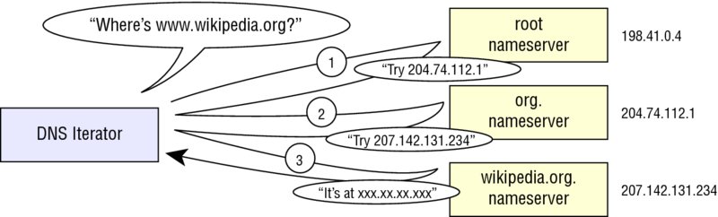

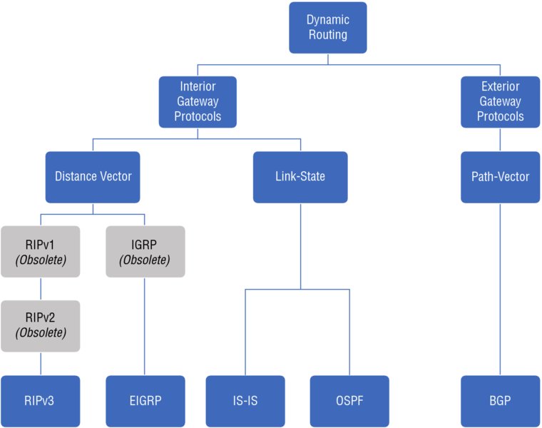


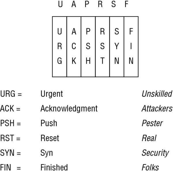
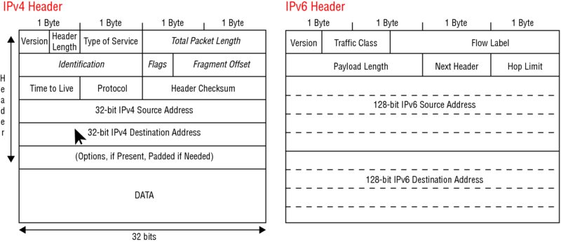

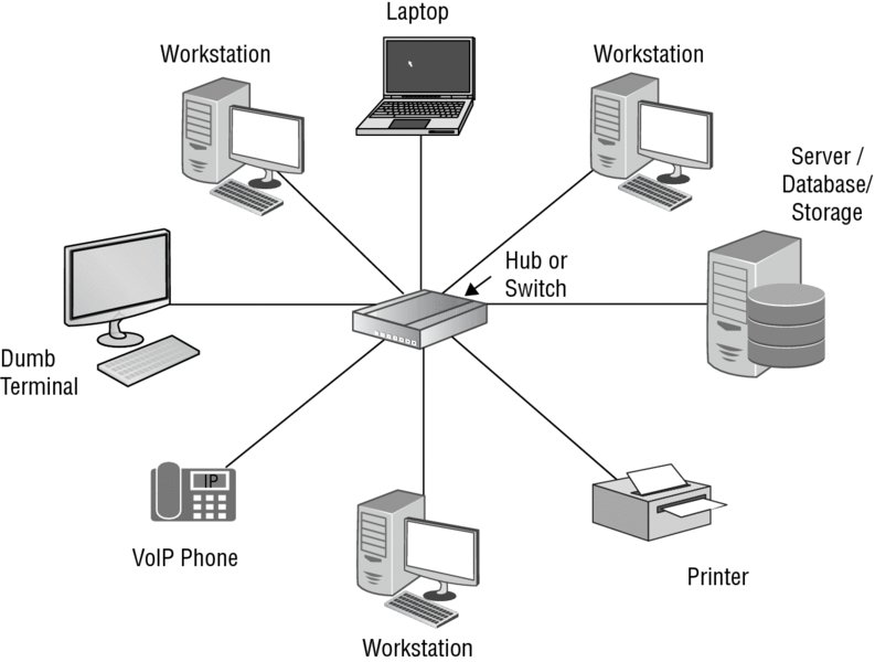
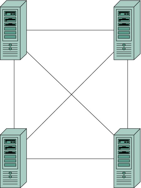


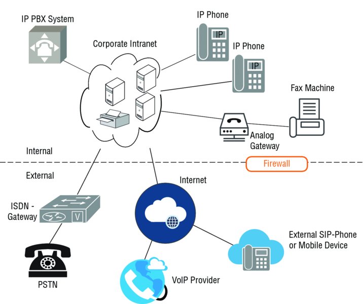


#/media/File:Geographies_of_Tor.png)