Building-integrated photovoltaics (BIPV)
C. Ferrara; H.R. Wilson; W. Sprenger Fraunhofer Institute for Solar Energy Systems, Freiburg, Germany
Abstract
This chapter presents best practice for the design and operation of building-integrated PV systems and performance issues arising from the building application, multifunctionality and shading. Requirements on BIPV installations as part of a future energy system are discussed with respect of regulations and standardization. Recommendations are made on approaches to monitor and validate meteorological and electrical data to ensure BIPV system output. Finally, an outlook is given on new approaches to define and design BIPV systems.
Keywords
Building-integrated photovoltaics (BIPV); Design; Electricity yield simulation; Electrical and meteorological measurements; Electric performance assesment; Monitoring; Building applications; PV building products
8.1 Introduction
8.1.1 Future energy system and building-integrated photovoltaics
In the near to mid-term future, our energy demand will be met by an energy system based on 100% renewable energy sources such as wind, hydroelectricity, biomass and solar energy [solar thermal and photovoltaic (PV)]. PV, including building-integrated PV (BIPV), will be one part of this future energy system.
Worldwide energy systems are currently undergoing a transition from highly centralized, large fossil and nuclear power plants to decentralized, small and medium-sized renewable power plants. For example, in Germany in 2014, 25.8% of the total electricity supply was provided by renewable sources (wind 3.4%, biomass 7.0%, solar 5.8%, hydroelectric power 8.6% and domestic waste 1.0%) [1]. This 5.8% of 610 TWh is generated by an installed PV power capacity of 38 GWp.1 Recent studies by Fraunhofer ISE [2] show that for the reduction of carbon dioxide (CO2) emissions by 80–95% of the complete energy system, we need among other measures up to 122–290 GWp installed PV power in Germany, corresponding to ~ 1200–2900 km2 (with a total area of 360,000 km2 equal to 0.78%, in comparison to 13.4% settlement and transport-related areas [3]). With roughly 80 million inhabitants in Germany, the area needed for PV installations results in 25–31 m2/capita, compared to ~ 300 m2/capita for settlement. To minimize further sealing of land, it seems obvious to use existing built-up areas for the installation of PV systems. In Germany, between 1500 and 3000 km2 of roof and façade area is available on existing buildings. An obvious option is to install PV systems on buildings.
8.1.2 BIPV – requirements and definition
When a PV module is designed as a BIPV module and integrated in to a building envelope, it is converted from a purely electrical device to a construction product that generates electricity, among other features. Thus, BIPV modules are subject to all local conditions (relating to climate, building code, construction, etc.), and national and international regulations regarding construction products. In this function, they replace traditional construction elements like roof and façade cladding, windows, blinds and static or dynamic shading elements. When a BIPV module replaces traditional construction elements, it assumes the function of the replaced building element (definition of BIPV, source: EN 50583 [4]). Taking the European Construction Product Regulation [5] as a guide, the building element's functions in the context of BIPV are one or more of the following:
• mechanical rigidity or structural integrity
• primary weather impact protection: rain, snow, wind and hail
• energy economy, such as shading, daylighting and thermal insulation
• fire protection
• noise protection
• separation between indoor and outdoor environments
• security, shelter or safety.
8.1.3 Costs of BIPV
According to Renken [6], the costs per square metre of BIPV modules replacing façade elements are similar to common cladding materials. Frontini et al. [7] published similar results for façades but found a difference of roughly 200 €/m2 compared to conventional roofing materials (Table 8.1).
Table 8.1
Comparison of prices of cladding materials for facades in Switzerland 2015
| Example | Cladding materials | Price per m2 [CHF]/[Euro]a |
| 1 | Wood | 220.00/198.00 |
| 2 | Fibre cement | 310.00/279.00 |
| 3 | Natural stone | 360.00/324.00 |
| 4 | Coloured glass | 145.00/130.50 |
| 5 | Aluminium | 130.00/117.00 |
| 6 | Acrylic glass | 155.00/139.50 |
| 7 | PV panel crystalline—glass/back sheet | 200.00/180.00 |
| 8 | PV panel crystalline—glass/glass translucent | 500.00/450.00 |
| 9 | Thin film PV panel—fixed dimensionsb | 80.00/72.00 |
a Original prices in CHF, conversion factor 0.90 (03 Feb. 2016) [6].
b Not suitable for BIPV.
8.1.4 Operation and maintenance
PV technology provides on-site renewable energy, it is silent, there are no hazardous emissions during operation and as it intrinsically has no moving parts, it needs little maintenance during its expected lifetime of 25–30 years, qualities that recommend it for building-integrated use. The need to clean BIPV systems is highly dependent on their geographical place of installation and the meteorological conditions (rain, humidity, wind, dust, etc.), the tilt angle of the system and the surface morphology. Studies on the impact of soiling and cleaning have been performed on field-mounted PV systems installed [8,9] comparably to roof-mounted BIPV systems. They find a maximum degradation in efficiency of approximately 6%. Depending on all these factors mentioned, cleaning can improve the overall efficiency of BIPV systems (Fig. 8.1).

8.1.5 Current obstacles
Although the mentioned facts are obvious, there is still no consistent market for BIPV. Several obstacles are causing this status quo. The planning and construction process is currently greatly complicated by the use of BIPV, because the recently approved BIPV standard EN 50583 is not yet widely known, there are only a few certified BIPV construction products and no easy installation methods (plug and play, plug and function) for BIPV. BIPV construction products are not yet integrated into widely available construction product catalogues and planning tools. As a result, the planning and installation effort is high and for many projects, specialists are needed for the electrical design and wiring of the BIPV systems. Only a small number of architects, engineers and planners are aware of the different technologies, their potential and advantages when installed on a building. During the design and construction process, BIPV is not part of the early design phase, because of the reasons mentioned here, and because of a lack of awareness by architects and planners. This finally leads to higher costs and limited application of BIPV.
8.2 Best practice for design
PV is, in a diluted form, already ubiquitous, starting from mW on watches, calculators, bags, etc. and extending to GW-scale PV power plants (eg, Solar Star Project, Capacity: 579 MW, USA [15]). BIPV, starting with some kWp on free-standing houses (≥ 5 m2) and reaching MWp scale on industrial and administrative buildings (≥ 5000 m2), is in the middle of this range. As buildings are very heterogeneous regarding size, usage, construction, etc., there will be a variety of BIPV modules for all buildings. In the medium term, we will see mainly customized BIPV in many locations. Alternatively, it can be camouflaged by new materials and still generate electricity on roofs and façades.
As we have seen in the previous subsection, there are several requirements coming from the construction of the building itself and from building regulations addressing mechanical stability, residual load capacity, fire safety, etc., as well as design issues. These requirements lead to the definition of the following construction classification.
8.2.1 Mechanical properties
Rigid BIPV modules
Rigid BIPV modules can be constructed using all PV technologies available on the market by including a rigid substructure or back sheet, such as sheets of glass or metal plates. They differ in module electrical efficiency, depending on the technology used (see Table 8.2). Based on their mechanical properties, rigid BIPV modules can easily replace conventional cladding materials for façades and roofs. It is important to note here that they have to fulfil the same requirements defined by national building codes (see the next section) and constructional requirements (Fig. 8.2).
Table 8.2
Maximum efficiency of photovoltaic technologies achieved in lab dimensions [10] and efficiency of PV modules from production lines [11]
| Technology | Max. efficiency (%) | Module efficiency (%) | Required area (m2/kWp) |
| c-Si | 25.0 | 22.9 | 4.4 |
| CIGS | 22.3 | 17.5 | 5.7 |
| CdTe | 21.5 | 17.5 | 5.7 |
| a-Si | 13.6 | 10.9 | 9.2 |
| DSC | 11.9 | n.a. | n.a. |
| OPV | 11.5 | n.a. | n.a. |

The required area is the active area of a module on the building envelope plus 10% for construction and safety issues. n.a., data not available.

Flexible BIPV modules
Flexible BIPV modules can be constructed with all so-called new technologies such as organic PV (OPV), dye-sensitized solar cells (DSC), perovskite solar cells (PSC) and all thin-film technologies, including amorphous silicon (a-Si), microcrystalline silicon (μ-Si), a combination of a-Si/μ-Si, copper indium gallium selenide (CIGS) and cadmium telluride (CdTe). The substructure can be based on polymer films or metal sheeting (Fig. 8.3).

8.2.2 Optical properties
Coloured BIPV modules
All so-called new technologies (DSC, OPV and PSC) have intrinsic potential for different colours. The materials of thin-film and crystalline technologies can be coloured to a limited extent or the appearance changed by the use of coloured front covers, either polymer sheets or glass. Adding coloured layers in front of the PV-active components of a module will reduce efficiency of the module (Fig. 8.4).
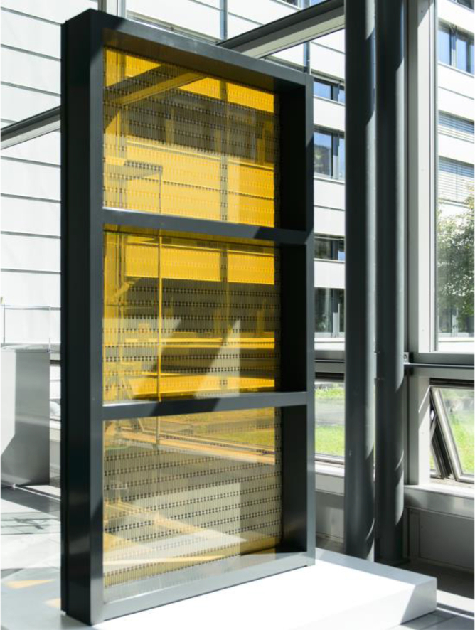
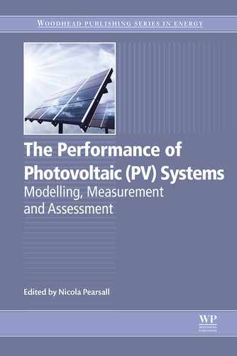
Transparent BIPV modules
Physical principles determine that it is not possible to make a 100% transparent BIPV module, because the PV active layer has to absorb some of the incident irradiation to convert it into electricity. There are examples of thin-film based BIPV modules [a-Si (ASI THRU by SCHOTT), CIGS] that have a semitransparent appearance, because they apply transparent conductive oxides instead of metals for the electrodes and are coloured in a neutral grey tone. Another possibility is to vary the distance between the PV-active areas and so enhance the transparency of the BIPV module and simultaneously reduce the area-specific efficiency. With windows, one can find different approaches, eg, angle-selective systems such as PVShade® (Fig. 8.5) (https://www.ise.fraunhofer.de/en/press-and-media/press-releases/presseinformationen-2013/fraunhofer-ise-inaugurates-new-energy-efficient-laboratory-building) or nearly invisible ones like Pythagoras Solar (http://www.glasswebsite.com/divisions/energy/profiles/pythagoras.asp), where the PV-active layer is inserted horizontally into the space between two panes attached to a special prism.
Due to the limited area on roof and façade areas, the BIPV system efficiency should be as high as possible. To optimize the energy yield of BIPV systems in mostly heterogeneous irradiation situations, a detailed electrical design is needed (see next subsection).
From this broad range of technologies, it is possible to define a wide variety of BIPV systems. In future, BIPV will be a commodity building product, including new technologies with advanced design possibilities and clearly defined multifunctionality (colouring, patterns, advertising, etc.). Most of the new technologies allow inherently different colours and semitransparency, so they have a large design potential. The use of this large design potential will open and boost new market segments for BIPV products, with its main focus on design requirements.
8.2.3 Electrical design of BIPV systems
The installation of BIPV systems needs a lot of electrical planning. Until now, the electrical design of BIPV systems has to be defined by (expensive) specialists. In a BIM implementation in the future, these calculations may be automated to a large extent.
There are several differences between a free-standing PV plant or a rooftop PV application and a BIPV system. First, the irradiation on the PV cells is inhomogeneous in almost all cases. There may be parts of the building that cause partial shading, there may be different orientations of the involved BIPV modules, and shading and even reflections from surrounding objects (buildings) can cause inhomogeneous irradiation on the PV cells. If this is the case, the problem of electrical mismatch arises. Any electrical connection of PV cells in series will lead to the situation that the PV cell with the lowest irradiation defines the current of all other PV cells connected in series to it. If the BIPV elements involved have different orientations and are connected in series with each other, the BIPV elements receiving lower irradiation values will define the current of the whole PV module string, leading to serious power losses (Fig. 8.6).

Most BIPV systems are connected to the grid. This makes it necessary to convert the DC power to AC, which is done with an inverter. These inverters again have limited ranges of acceptable electrical DC specifications. If the power of a PV system drops to a value significantly below the nominal MPP power, the inverter may change its operation mode to constant-voltage, leading to an additional power loss. However, if the DC quantities exceed the inverter specifications, the inverter may be damaged. For this reason, it is very important to understand the electrical details of the BIPV electricity production. The electric circuit of the BIPV system (especially combining the PV modules in series and parallel circuits; the choice of the appropriate inverter specifications) needs to be calculated in advance. Automating this procedure within the BIM context will not only simplify the planning process dramatically, but it will also simplify the procedures that are necessary if any BIPV-relevant changes in the construction process occur. Last, but not least, the measured power generated by the PV system can be compared with simulations to check whether the BIPV system is working properly.
8.3 BIPV requirements and constraints
8.3.1 BIPV regulations and standardization efforts
When applying PV as a construction product, two worlds have to be combined. On the one hand, the cost-effective production of a PV module requires a highly automated, technical process. For this reason, PV manufacturing companies need to be involved. Their main market, however, is the production of PV modules that are used for free-standing PV plants or rooftop PV applications. On the other hand, every construction product in the EU needs to comply with the Construction Products Regulation (CPR), leading to many additional requirements for the PV modules, such as higher demands on fire safety or post-breakage behaviour. Furthermore, some basic properties of PV modules, especially the dimensions, need to be adapted to the situation of the building.
Not many manufacturers of PV modules are able to produce PV modules with customized dimensions. Due to their main market, the automated processes that are needed for the production of PV modules do not allow the size of the PV modules to be changed arbitrarily. Furthermore, their automation process does not always allow PV modules to be manufactured with the appropriate mechanical specifications that construction products need to have.
There are several companies worldwide that have specialized their manufacturing process for BIPV applications. They are based on a number of different technological approaches. Similar to the main PV market of free-standing and rooftop PV applications, the wafer-based PV technologies (monocrystalline and polycrystalline silicon, heterojunction technology, etc.) are the leading PV technologies for building products, although the aesthetic options that these PV technologies provide are limited. Besides the high efficiency of the wafer-based PV technologies and their status of development, it is the strong similarity of glass–glass modules to laminated glass panes that simplifies their application as a construction product. Large parts of the already existing standardization procedures for glass-based construction products can be easily adapted for glass-glass PV modules.
For BIPV manufacturers, it is of major importance that standardized testing procedures are developed to judge the suitability of their products to defined applications. In Europe, each country still has its own legal procedures for building products. For BIPV, this is a serious constraint due to the limited demand for BIPV products within the limited market of a country. In 2015, the EU member states agreed on the European standard EN 50583 with the title ‘Photovoltaics in buildings’. Due to legal procedures, it will take several additional years until the European standard will be valid within the EU member states.
The standard EN 50583 is the furthest developed standardization effort worldwide on the topic of PV in buildings to date. Besides listing the standardized procedures for electrical testing of the PV modules, it summarizes a long list of relevant mechanical testing procedures that have to be taken into account when using PV modules as construction products.
The EN standard defines five different categories of BIPV (Fig. 8.7).

The aforementioned BIPV standard lists all the building standards that need to be taken into account for PV modules that are used as a construction product, depending on the intended category of application.
On an international level, there are standardization efforts from ISO (eg, BS ISO 18178) as well as from IEC (IEC 62980). Both standards, however, are still under development and do not reach the degree of detail of EN 50583 at the moment.
8.3.2 Photovoltaics in the construction sector
Until now, building projects with BIPV elements installed are within a niche market and do not necessarily comply with common procedures of the building sector. Especially for large building projects, the involved companies are used to working with a 3D object-based representation of the whole building project. Companies already offer commercially available software programs with databases of construction products, each with all the information that is necessary for the construction process of the building. On the basis of these objects, the software programs offer a wide range of automated calculations from cost calculations to earthquake stability. Building elements that are not part of the available databases only have a very limited chance to be considered in sophisticated construction projects.
As soon as BIPV modules are available as database objects, including all the information that is needed in the construction process, BIPV systems will be able to take the step from niche market to standardized commodity product. With the development of BIPV standards and the availability of corresponding BIPV products, the next step to be taken is to create IT representations of these BIPV products for the building sector. Unfortunately, the number of PV researchers that are simultaneously aware of the needs and common procedures of the building industry is very limited.
When using PV modules as building elements, the effort for planning is very large. The electrical design of the BIPV system often needs time-consuming simulations. However, BIPV is not the only challenging topic in the building sector. The larger a building project is, the larger is the number of different companies involved, and different simulation programs are applied. During the last decade, there has been widespread discussion on how to simplify the IT procedures when topological representation formats of different simulation programs have to be combined.
The solution, called BIM (building information modelling), arises from agreement on a software-independent data structure that includes all the relevant information for the construction process and can be extended by all kinds of proprietary software programs. This independent data structure is mainly developed by the buildingSMART organization (http://www.buildingsmart.org). The IFC format that has been codified in ISO 16739 has already been incorporated into many commercial CAD programs.
The general development of BIM is also a huge opportunity for the BIPV topic. The development of a standard procedure to define the relevant mechanical, electrical or economic properties of BIPV products can decide whether they will be implemented in the IT representation of the construction process or not. It will be decided by the efforts of the PV community whether building integration will become a relevant PV application or if it will be limited to a niche market in the future as well.
For smaller building projects, the communication between people involved in the planning and installation of BIPV systems can be optimized without the generation of a general data structure. All planning and exchange of information should always include the period of operation and maintenance of the building and the installed BIPV system.
8.4 Measurement and assessment
8.4.1 Monitoring of electricity yield
As for conventional PV systems, continuous monitoring of BIPV systems is valuable as a prerequisite for determining whether the installation is generating the amount of electricity anticipated during the planning process. In the building context, not only is the return on investment resulting from the generated electricity of interest, but also the detection of performance deviation that may indicate safety or service lifetime-relevant issues such as hot-spot formation.
Recommended electrical and meteorological quantities for monitoring
The primary electrical quantity to be monitored is the output AC power from each inverter. Measurement of the DC current and voltage of each module string allows the system performance to be analysed in greater detail and enables better localization of faults, should they occur.
The solar irradiance in the module plane and the ambient temperature are the most important meteorological quantities to be monitored. If the BIPV system combines modules with many different orientations, an alternative concept is to measure the global irradiance in a horizontal plane and either the diffuse irradiance on a horizontal plane or the direct irradiance, and use these measured quantities as input data to sky luminance models, from which the irradiance on differently oriented planes can be calculated in turn. Direct measurement of the module temperature, using sensors attached to the back surface of the modules, is recommended if accurate performance analysis is intended. Because cooling of the BIPV modules by wind has only a second-order effect on the generated power, the wind speed and direction would generally be monitored only in systems that are to be analysed at a very detailed level.
A 10 s sampling interval and recording of 1 or 5 min averages of the monitored quantities with data loggers have proved to provide a good data basis for further analysis in most cases.
Presentation and analysis of monitored data
For a quick visual check that the BIPV is performing within plausible limits, a numerical or graphical display of the instantaneous irradiance on the module plane and the generated AC power may be adequate. Time series of the same two quantities or their hourly, daily, monthly and annual averages or time-integrated values also allow quick plausibility checks.
To assess the electrical performance in more detail, time series of the performance ratio (PR) for periods of a day, a month or a year are widely used, as the PR is defined to compensate the first-order effect of the varying solar irradiance in the module plane on the electricity yield. As the irradiance in the module plane is a fundamental parameter for calculating the PR, it should be calculated separately for each significantly different module orientation in the BIPV system, using the relevant irradiance value. A PR of 100% indicates that the analysed system is generating the same amount of electricity as the installed modules would under STC (STC: irradiance of 1000 Wm− 2; solar spectral distribution corresponding to AM 1.5, global; ambient temperature of 25°C). The frequent occurrence in BIPV installations of significantly lower irradiance values, resulting from the orientation defined by the building envelope, and higher module temperatures in better thermally insulated positions than for STC, both having a negative effect on the module efficiency, mean that the PR is usually below 80%. In the BIPV context, time series of the PR are most useful to identify sudden changes, which may indicate significant component failures, or gradual changes, which may be caused by soiling or degradation.
At the most sophisticated level, time series of the monitored electrical yield can be compared with the results of simulations based on the monitored meteorological quantities, as described in Sprenger [12]. Due to the effect of shading, which is likely to be more frequent and more complex in BIPV installations than in ground-based PV systems, this type of detailed comparison is needed both to determine whether the system is performing according to expectations and to detect component failures. Otherwise, false alarms concerning the system output may be frequently triggered by partial shading of module arrays.
8.4.2 Practical aspects
It is worth explicitly noting that providing an accessible location for the inverters, being essential components of any PV system, should be part of the standard electrical planning for the building—just as for a fuse box.
In contrast to conventional PV systems, the positions for locating most of the meteorological sensors are no longer easily accessible once the BIPV modules have been installed (and the scaffolding removed). Thus, it is strongly recommended to take the monitoring system into account during the early phases of the planning process and to ensure that the required sensors and cabling are available for installation together with the BIPV system installation. As the sensors for the electrical quantities are usually located near the inverters, the problem of accessibility is usually not as acute as for the meteorological sensors, but space must still be planned for installation of additional junction boxes and electrical cabinets housing the data acquisition and transmission systems.
If a significant fault in a BIPV system is identified, deciding on the appropriate course of action is less straightforward than in ground-based systems. Not only the effect on the electrical yield but also aesthetic aspects (colour matching), accessibility and human safety will affect the decision. Thermographic images recorded with an IR camera may be useful in this context to localize hot spots and determine whether they present a fire risk.
8.4.3 Requirements for BIPV modules as building components
As construction products, BIPV modules in Europe must fulfil the so-called ‘essential requirements’ specified in the European Construction Product Regulation CPR 305/2011 [4].
The essential requirements defined in the CPR 305/2011 are:
1. mechanical resistance and stability,
2. safety in case of fire,
3. hygiene, health and the environment,
4. safety and accessibility in use,
5. protection against noise,
6. energy economy and heat retention and
7. sustainable use of natural resources.
The characteristics required of a specific BIPV module will depend on the function it assumes within the building envelope, replacing transparent or opaque building components for the walls or the roof, and the location of the building. Following the approach of the recently approved EN 50583, titled ‘Photovoltaics in Buildings’, BIPV modules can be classified as those including glass panes or those based on polymer or metal substrates. The characteristics specified for similar building products, eg, glass laminates, polymer-based waterproofing sheets or extruded metal roofing sheets, must then also be determined for BIPV modules that provide the same function within the building.
For example, if a semitransparent glass-glass PV module is to be used as the outer pane of a triple glazing unit, measurements of the transmittance and reflectance spectra and the thermal emissivity of that module will be needed, so that the light transmittance, the total solar energy transmittance (g value), the colour rendering and the thermal transmittance (U value) of the glazing unit can be calculated. If the same semitransparent glass-glass PV module is a component of overhead glazing for a bus shelter, its mechanical strength must comply with local authorization requirements based on specified snow, wind and hail loads.
The reader is referred to EN 50583 for a comprehensive (but not exhaustive) set of standards detailing the construction-related characteristics which must be determined for BIPV modules acting as different types of building components. These standards typically define characteristics which can be determined under stationary conditions in the laboratory. Although the transmittance characteristics listed here as examples are actually dynamic quantities which depend on the prevailing environmental conditions, long-term monitoring of their variation in the installed component requires rather more elaborate measurement technology than to determine the amount of electricity generated by a BIPV installation.
8.4.4 Economic assessment of BIPV systems
The life-cycle costing model developed at Fraunhofer ISE for BIPV systems considers three main phases of the system lifetime from the point of view of the system owner: the investment/installation phase, the operation phase and the demolition/disposal phase [13]. Throughout the system lifetime, which is typically assumed to be 20 or 25 years, the annual cash flows (income and expenditure) are determined, taking financing costs and inflation rates into account, to determine the net present value of the whole system at any given time.
The cash flows during the first phase are mainly outward, including the investment for system components (BIPV modules, cabling, inverters, mounting structure, monitoring equipment) and planning, authorization and installation costs. However, a bonus representing the cost of substituted building components may also be taken into account. In doing so, it is useful to define the system boundary to exclude components such as substructure that could equally well be used for mounting BIPV or the substituted, conventional building components.
During operation, ongoing expenses for cleaning, maintenance, monitoring and administration are accompanied by income resulting from the electricity generated by the system. This may be in the form of real income from feeding electricity into the public grid, or saved expenditure for externally generated electricity due to in-house usage of the electricity generated on site. Depending on their thermal and optical properties and their function within the building envelope, BIPV modules may also affect the building's thermal and lighting energy balance; the financial effect can also be included in the cash flows for the operation phase.
Finally, demolition and disposal will again incur expenses, but income may also be generated from selling the component materials (eg, copper cables) for recycling.
Depending on the relative value of the inward and outward cash flows, BIPV systems can amortise themselves within their system lifetime, a property not otherwise expected of or found in conventional, ‘passive’ building components.
8.5 Product development
8.5.1 Complementary technical approaches
Presently, two technical approaches are being applied to reduce costs and increase application of BIPV in renovation of existing buildings and new construction.
One is to produce customized BIPV modules in a highly automized production line that allows differences in size, colour and power output. For the electrical design of BIPV systems combining modules with such diverse parameters, including orientation and tilt angle, experts and expert systems are needed to simulate an optimized electrical configuration for a given geometrical configuration, taking the surroundings and neighbouring buildings into account. Currently, automated simulation systems that are directly linked to CAD and BIM systems are being developed.
Another approach is to identify building classes with standard constructions and dimensions by detailed analysis of the building stock. The resulting detailed data basis allows the definition of standardized modules that can be prefabricated indoors and are equipped with plug-and-play technology. These BIPV modules therefore feature a high-quality standard on the one hand and can be installed more quickly on the other.
8.5.2 BIPV applications
For existing buildings and new construction, there are several possibilities to integrate PV technologies into buildings, eg, as roofing material, in façade systems, in window systems (eg, the angle-selective PVShade® product), as horizontal and vertical shading systems, integrated into venetian blinds or window shutters (see Fig. 8.7). Many design possibilities are given by the range of possible colours, forms, patterns and flexible dimensions.
Some examples that are entering the market include:
• SBskin, a highly insulating glass block with integrated DSC, for roofs and façades.
• TIFAIN, adaptable shading system with DSC.
• SwissInso, new colour system for whole modules with minimal reduction of PV efficiency.
• Multiwire (SCHMID Group)/SmartWire Connection Technology (SWCT, Meyer Burger) concepts, making intercell connectors less visible.
A detailed product overview of market available BIPV systems for roofs and façades has been published by Frontini et al. [7].
For each application, it is important to understand, design and handle BIPV products as construction products, not only as PV modules. Combined roof and façade elements with additional layers and functions will increase the functionality and application of BIPV modules. Further business is stimulated by the return of investment resulting from the electricity generated by BIPV components, a unique property for building products.
Extended application and interpretation will be generated by the use of BIPV in the urban context as urban furniture such as bus shelters and roofs for parking lots.
Today, prices for BIPV are often calculated and published as €/Wp, or €/kWh; in future, €/m2 will be more important to concur with construction industry practice and the thinking of architects and planners. The objective prices for standard PV modules are helpful as a guide; they are expected to decrease from 0.53 €/Wp today to 0.20–0.30 €/Wp in 2030 [14]. Assuming the development of standardized BIPV modules for selected building categories, one can extrapolate additional costs for BIPV systems of approx. 100 €/m2 to the near future.