In Chapter 4 we briefly discussed the gears in the NXT 2.0 set. We noted that their general purpose is to transmit motion, and we outlined three subcategories: bevel gears, double bevel gears, and “other” gears. In this chapter we’ll expand our discussion of the gears and learn how to effectively transmit motion through a variety of gearing techniques. We’ll begin with a key gearing concept, the gear train, and establish some important terminology. Then we’ll explore how to properly control the performance and manage the assembly of systems of gears.
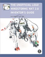
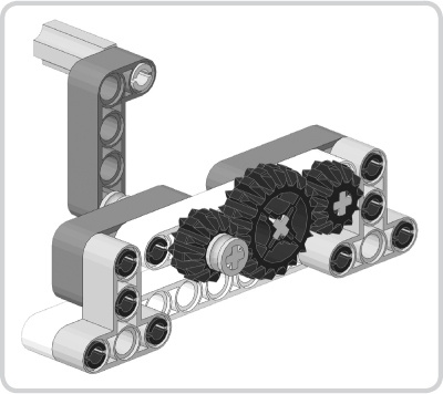
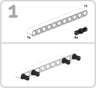
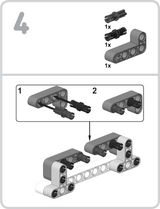
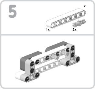
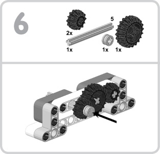
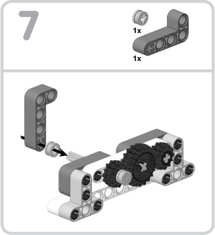
Whenever we use two or more gears to transmit motion, we call the series of gears a gear train. To help us understand some of the concepts surrounding the gear train, let’s build a simple mechanism (Figure 6-1) with a crank that can turn three gears. The following eight steps present the building instructions for this mechanism.

Note
Make sure that you do not push the 5M rightangled beam too tightly onto the 5M axle or else the crank will not turn smoothly.

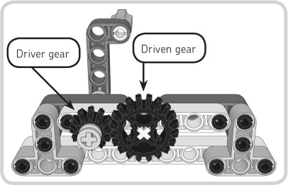
Now that you’ve built the mechanism, we can begin discussing the gear train. First, within a gear train, a gear can serve one of three roles: the driver gear, the driven gear, or an idler gear. Figure 6-2 shows which gears perform which roles in the mechanism you just built. The driver gear is the first gear in the gear train or, in other words, the first gear to transmit motion. The driven gear is the last gear in the gear train or, in other words, the last gear to transmit motion.

Figure 6-2. A gear can serve one of three roles in a gear train: the driver gear, the driven gear, or an idler gear.
Finally, an idler gear serves two purposes. The first purpose is to transmit motion from the driver gear to the driven gear when they’re too far apart for their teeth to mesh. The second purpose is to reverse the direction of rotation. A fundamental property of gears is that any two engaged gears revolve in opposite directions. Hence, we can control whether a driven gear rotates clockwise or counterclockwise by including an idler gear in the gear train.
Note
Although you can often successfully mount idler gears on smooth axle pegs, it is more common to mount driven gears on axles; you usually want to attach pieces to the driven gear’s rotating axle.
If you turn the crank on the mechanism, you can see the 20t double bevel idler gear perform both of its functions. First, it transmits motion from the 12t double bevel driver gear to the 12t double bevel driven gear. Second, it reverses the direction of rotation, causing the driven gear to revolve in the same direction as the driver gear. If the driver gear revolves clockwise, for example, the idler gear revolves counterclockwise, and then the driven gear revolves clockwise.
Note
In order for the driver gear and the driven gear to revolve in the same direction, the gear train must consist of an odd number of gears. Compound gear trains, which we’ll cover in Compound Gearing: Achieving Greater Torque or Speed, are an exception to this rule.
This gear train has only one idler gear, but you can theoretically have as many idler gears in a gear train as you want—or none at all. More gears introduce more friction, which is not desirable. In addition, more gears introduce more backlash, which is the gap between each pair of meshing gears. If you jiggle the crank on your mechanism—just barely—you’ll notice that the driver gear can move a little without turning the other gears. This gap is the backlash. When using many gears, backlash can become a problem. Thus, where possible, having fewer gears is better than having more gears.
Not every gear train performs the same. When referring to a gear train’s performance, we’re talking about the speed and torque of the driven gear’s axle. In simplified terms, speed is how fast the axle revolves, and torque is the strength or power with which the axle revolves. Using several techniques—gearing down, gearing up, and compound gearing—we can control a gear train’s performance, adjusting it for specific purposes. Before exploring these topics, however, we must discuss gear ratios.
We can measure or describe the performance of a gear train with a gear ratio, which is the number of rotations of the driver gear relative to the number of rotations of the driven gear. For example, a gear ratio of 1:3 (pronounced one to three) indicates that for every rotation of the driver gear, the driven gear rotates three times. You’ll learn how gear ratios relate to speed and torque in a moment when we discuss the techniques for controlling a gear train’s performance. Let’s first concentrate on how to calculate gear ratios themselves, beginning with two basic gearing principles.
First, each tooth on a gear can turn exactly one tooth on another gear. If a gear train consists of two gears, each with the same number of teeth, the gear ratio for that gear train would be 1:1. That is, for every rotation of the driver gear, the driven gear also completes one rotation. Therefore, by comparing the number of teeth on the driver gear to the number of teeth on the driven gear, we can determine how many rotations the gears will complete relative to each other.
Second, idler gears don’t affect performance except in regard to friction. We ignore any idler gears in a gear train when determining a gear ratio. The gear ratio of the mechanism we built earlier would be 1:1 because the driver gear and driven gear have the same number of teeth and the 20t double bevel gear is only an idler gear.
With these concepts in mind, we can follow a simple three-step method to determine the gear ratio of most LEGO gear trains. Let’s quickly modify our mechanism and then use this method to determine its gear ratio. Remove the driven gear and its smooth axle peg so that the mechanism looks like the one in Figure 6-3. The 12t double bevel gear is still the driver gear, but now the 20t double bevel gear is the driven gear. Follow these steps to determine the gear ratio:
Determine the number of teeth on the driver gear and driven gear. In our example, the driver gear has 12 teeth and the driven gear has 20 teeth.
Form a ratio with the driven gear’s teeth first and the driver gear’s teeth second. Continuing our example, we would have a ratio of 20:12.
Simplify the ratio to its lowest terms. In this case, 20:12 simplifies to 5:3. That is, for every five rotations of the driver gear, the driven gear rotates three times.
Gearing down a gear train increases its torque but decreases its speed. We can gear down by driving a larger gear with a smaller one. When we gear down, the resulting gear ratio will always consist of a larger number followed by a smaller number because the driver gear completes more rotations than the driven gear (e.g., 5:3 or 3:1). The gear train in Figure 6-4 shows a 12t double bevel gear driving a 36t double bevel gear. By following our three-step method, we are able to determine that the gear ratio is 3:1. This ratio tells us that the driver gear rotates three times for every one rotation of the driven gear; speed decreases by a factor of three, but torque increases by a factor of three.

Gearing up a gear train increases its speed but decreases its torque. We can gear up by driving a smaller gear with a larger one. When we gear up, the resulting gear ratio will always consist of a smaller number followed by a larger number because the driver gear has more teeth and completes fewer rotations than the driven gear (e.g., 1:3 or 3:5). The gear train in Figure 6-5 shows a 36t double bevel gear driving a 12t double bevel gear, which produces a gear ratio of 1:3. This ratio tells us that the driver gear completes one rotation for every three rotations of the driven gear; speed increases by a factor of three, but torque decreases by a factor of three.

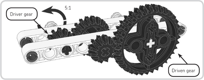
We just saw that a 12t double bevel gear and a 36t double bevel gear can produce ratios of either 1:3 or 3:1. What if you want to achieve gear ratios that provide even more torque or speed? We can implement a powerful technique known as compound gearing, which places two gears on the same axle. We call a gear train that uses this technique a compound gear train. Figure 6-6 shows a compound gear train with four gears: two 12t double bevel gears, a 20t double bevel gear, and a 36t double bevel gear. A 12t double bevel gear and a 20t double bevel gear share an axle in the middle of the gear train. What is the gear ratio of this compound gear train? Let’s calculate it.
Calculating the gear ratio of a compound gear train is a bit different than calculating the gear ratio of a regular gear train. Follow these steps:
Determine the number of teeth on the driver gear, the driven gear, and any gears that share an axle. In our example, we have to count the teeth on all the gears. The driver gear has 12 teeth, the driven gear has 36 teeth, and the two gears that share an axle in the middle of the gear train have 12 teeth and 20 teeth, respectively.
Calculate the gear ratios. Continuing our example, the first pair of gears is a 12t double bevel gear driving a 20t double bevel gear, which results in a ratio of 5:3. The next pair of gears is a 12t double bevel gear driving a 36t double bevel gear, which means it results in a gear ratio of 3:1.
Multiply the gear ratios like fractions. In this case, multiplying 5:3 and 3:1 produces a gear ratio of 15:3.
Simplify the ratio to its lowest terms. Simplifying the 15:3 gear ratio from step 3 results in our final gear ratio of 5:1.
For every five rotations of the driver gear, the driven gear rotates once; the speed decreases by a factor of five, but the torque increases by a factor of five. If the 36t gear were the driver gear instead of the driven gear, the gear ratio would be 1:5. This is a simple example of compound gearing—it’s possible to gear up or down much more significantly by using multiple stages of compound gearing.
With all of these options for controlling gear train performance, you may be wondering when you should gear up, gear down, or do neither (i.e., use a gear ratio of 1:1). The answer depends on what purpose the gear train serves. For example, if the gear train is part of a mechanism that works with relatively heavy objects, gearing down for more torque would probably be the best choice. If it’s not immediately obvious how you should configure a gear train’s performance, experimenting with different gear ratios will help you decide.
If you’ve chosen to gear up or down, your next question would be, “How much?” As you work with the NXT servo motors and different gear trains, you’ll develop a sense for the strengths and speeds of various gear ratios, and you’ll soon know which ratios are best for which projects. Nevertheless, in many cases, further experimentation will still be the solution.
Note
As a general rule, don’t gear down simply for the sake of decreasing speed. If you need to decrease speed but don’t necessarily need to increase torque, you can use programming to decrease the speed of the motor powering the gear train. You’ll learn how to do this in Chapter 7, the first programming chapter.
Keep in mind that you’ll usually have to make a compromise between speed and torque. For example, if you’re creating a racecar-style NXT robot, you would want the robot to go as fast as possible. Does this mean you should gear up enormously to achieve maximum speed? Not exactly. If you gear up too highly, the torque will decrease so drastically that there won’t be enough power to move the car itself! In this case, it would be better to experiment and then settle on a gear ratio that gives the robot sufficient speed while still giving it enough torque to efficiently move.
The primary challenge when assembling a gear train—apart from deciding which gears to use—is in properly spacing each pair of gears. If the gears are too far apart or too close together, their teeth can’t mesh and therefore can’t transmit motion. How you should space the gears generally depends on whether they are on parallel axles or perpendicular axles.
The mechanism we built earlier exhibits the most basic type of gear train, which consists of parallel gears mounted in the same row of round-holes. With this setup, spacing is in increments of 1M because the round-holes on beams are separated by a distance of 1M. But how many round-holes apart should we space a given pair of gears? The module itself provides the answer.[5]
If we use the module to measure the radius of each of the double bevel gears in the NXT 2.0 set—the radius being the distance from the center of a gear to the outermost part of its teeth—we’ll gather the data presented in Table 6-1. (I have excluded the bevel gear and knob wheels because of differences in their design.) Adding the radii of any two gears tells us how far apart the gears’ axles must be in order for the gears’ teeth to mesh. The sum of the radii must be a whole number (1, 2, 3, and so on) because the round-holes are 1M apart.
Table 6-1. Radii of Double Bevel Gears in the NXT 2.0 Set
gear name | radius |
|---|---|
12t double bevel gear | 0.75M |
20t double bevel gear | 1.25M |
36t double bevel gear | 2.25M |
As shown in Table 6-1, a 12t double bevel gear has a radius of 0.75M and a 20t double bevel gear has a radius of 1.25M. Now we know why each pair of gears meshes perfectly in the mechanism we built at the beginning of this chapter: The sum of their radii is 2M, which is a whole number.
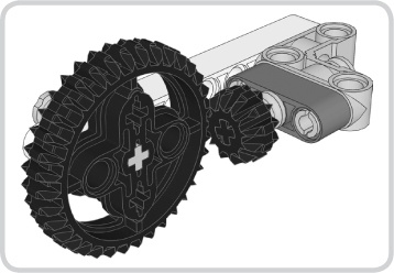
Let’s try another example. If you wanted to use a 12t double bevel gear (which has a radius of 0.75M) and a 36t double bevel gear (which has a radius of 2.25M), would this combination of gears work? Add up the radii of these gears, and you’ll get 3M. This is a whole number, so it will indeed work (Figure 6-7). How about using a 20t double bevel gear (1.25M) and an 36t double bevel gear (2.25M)? Add up the radii of these gears, and you’ll get 3.5M. This combination of gears won’t work because the sum of their radii is not a whole number.
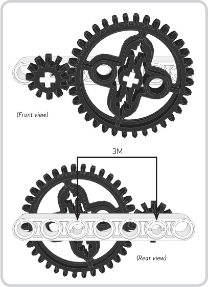
Figure 6-7. A 12t double bevel gear has a radius of 0.75M, and a 36t double bevel gear has a radius of 2.25M, so we must space the gears’ axles by 3M, the sum of the radii.
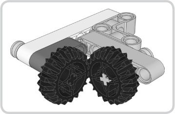
If you want to achieve an imperfect gear combination (i.e., a combination of gears in which the sum of the radii is not equal to a whole number), you can use clever techniques to approximate the necessary spacing. One method is to place the gears’ axles in round-holes on different levels (Figure 6-8). Another method is to position the gears on connector blocks rather than beams (Figure 6-9). You’ll simply need to experiment with these two techniques to find different ways of getting the gears’ teeth to mesh; just be aware that the teeth won’t ever mesh perfectly and, therefore, won’t perform completely effectively.
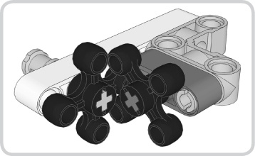
Also, how should you space knob wheels? Remember that you can only use a knob wheel with other knob wheels. When positioned on parallel axles, knob wheels should be spaced by 2M (Figure 6-10).

Figure 6-8. You can achieve imperfect gear combinations by positioning the gears in round-holes on different levels.
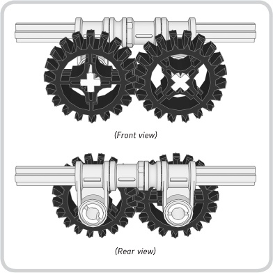
Figure 6-9. You can also achieve imperfect gear combinations by positioning the gears on connector blocks.
Figure 6-10. These two knob wheels demonstrate that spacing should be 2M when they are on parallel axles.
Don’t Forget the Spur Gears!
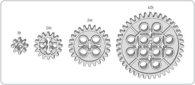
The simplest and most common LEGO gear in existence is the spur gear, which typically engages other gears positioned on parallel axles. The NXT 2.0 set doesn’t include any spur gears, but you should definitely plan on expanding your LEGO collection with at least the four basic spur gears: the 8t, 16t, 24t, and 40t gears (Figure 6-11). These gears are so common, in fact, that we actually drop the word spur from their name (e.g., 8t gear, not 8t spur gear). Table 6-2 lists the radii of these four spur gears.
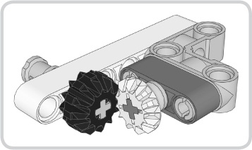
We can also use the gears in the NXT 2.0 set—the bevel gears, double bevel gears, and knob wheels—on perpendicular axles to transmit motion at right angles. With this type of gear train, we don’t add up the gears’ radii and try to calculate the necessary spacing. Instead, for any given combination of these gears, we simply experiment with the spacing until we find something that works. In fact, it is possible for any two gears from the NXT 2.0 set to successfully mesh at right angles. (Remember, though, that knob wheels can only mesh with other knob wheels.) Figure 6-12 through Figure 6-21 demonstrate a few of the ways gears can mesh at right angles. Try to build these simple gear trains to better understand how they function.
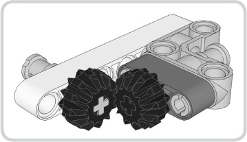
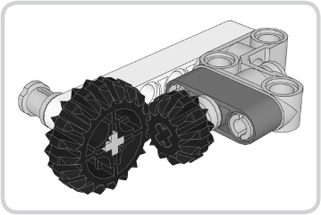
Figure 6-13. A 20t double bevel gear and a 12t double bevel gear engaging each other on perpendicular axles
Note
Some of these gear trains use one or more half-bushings to ensure that the gears mesh properly. However, the half-bushings are not visible in Figure 6-19, Figure 6-20, and Figure 6-21. In these particular figures, there is a half-bushing behind each gear.


After reading this chapter, you should have a solid understanding of the LEGO gears in the NXT 2.0 set—and perhaps a greater appreciation for them as well! We covered a number of gearing concepts, beginning with the gear train, which consists of two or more gears that transmit motion. We then moved on to controlling the performance of a gear train through techniques such as gearing up, gearing down, and compound gearing; and we also learned how to measure performance with the gear ratio. We then explored how to effectively assemble gear trains consisting of parallel gears or perpendicular gears, the two types of gear trains commonly found in NXT robots.
We’ve completed Part II, and after covering programming in Part III, you’ll learn even more about construction through the projects in Part IV.
[5] There are beams that have round-holes spaced differently than the round-holes on normal beams. The NXT 2.0 set doesn’t include any of these special beams, however.