While in the past few chapters we focused on using treads for mobility, this chapter presents the Jeep, a four-wheeled vehicle (Figure 14-1). The LEGO MINDSTORMS NXT 2.0 set includes four medium-sized wheels—and a matching set of tires, of course—which makes it incredibly fast, easy, and fun to build vehicles with wheels. But there are many possible ways to use wheels, as you’ll see in the Jeep’s front-wheel drive configuration.
You’ll begin by taking a brief look at how this front-wheel drive configuration works, and then we’ll build the Jeep. Next, you’ll program the Jeep to drive around a room while avoiding objects, and then you’ll create another program that enables it to follow a line using a color sensor. Finally, you’ll explore a few additional ideas for modifying the Jeep, including how to turn it into a self-parking car.
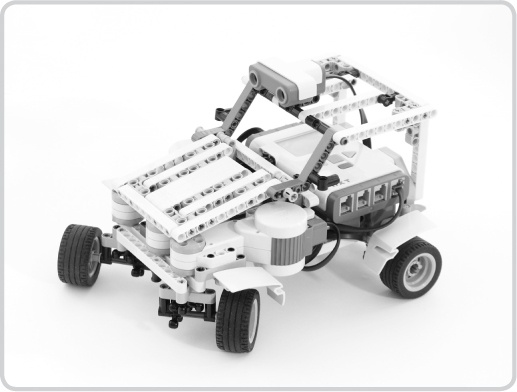
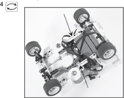
Like many real cars, the Jeep uses its front wheels to both drive and steer. As you can see in Figure 14-1, three motors provide this functionality. The outer two motors each power one front wheel, and the middle motor controls the steering of both front wheels. You’ll take a closer look at how both the steering and the driving work in this model.
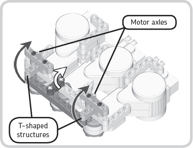
To understand how the Jeep steers, look at its underside with the wheels removed, as shown in Figure 14-2. First, when the middle motor turns (in the direction shown by the white arrow), the inverted cross block (the black piece) moves the 11M beam, shown here as a dark gray piece. This movement causes the T-shaped structures, each holding a wheel, to rotate (as shown by the black arrows). To steer in the opposite direction, the motor can simply rotate in that direction.
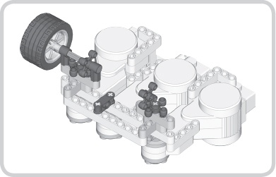
As you may have noticed in Figure 14-2, the T-shaped structures rotate around axles but are not fixed to the axles. The axles are connected to the outer two motors and can freely rotate to power the wheels without having any effect on the T-shaped compartments (Figure 14-3). Basically, each motor uses an axle to transfer its power, or rotating motion, to a set of knob wheels that then transfer the power to another axle that drives the wheel.
Simply powering the outer two motors at the same speed and controlling the middle motor to steer isn’t enough to make the Jeep drive around properly. Notice that when the vehicle steers as it drives, it drives in circles like a real car would (Figure 14-4). Imagine that each wheel leaves tracks as it drives in a counterclockwise circle so that two circles appear, one for each wheel. You’ll notice that the wheel on the left drives in a smaller circle than the one on the right. Consequently, once the vehicle has completed a full circle, the wheel on the left has traveled a shorter distance than the wheel on the right.
Because the left wheel travels a shorter distance, it should also turn slower relative to the other wheel so that it doesn’t slip. If the radius of the smaller circle is twice as small as the radius of the bigger circle, the distance traveled is also twice as small, meaning the wheel should turn twice as slowly.
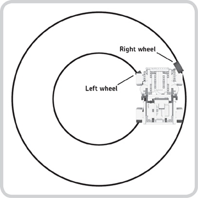
Figure 14-4. When a vehicle turns, the wheels should rotate at different speeds because they travel different distances during the turn. This is the case not only for a complete circle but also for any turn or curve. For example, in this turn to the left, the right wheel spins faster than the left one.
Note
The rear wheels of this car are not powered and can spin freely, so you won’t need to pay attention to them when adjusting speed. When you read “right wheel” or “left wheel,” we mean the front wheels only.
You can easily adjust the speed of each wheel by varying the power applied to its driving motor. As you’ll learn later, the NXT-G program you’ll create will do this for you. First, however, you need to know exactly how fast each wheel should spin in order to make the Jeep drive around without the wheels slipping.
As the middle motor rotates, the car makes an increasingly tighter turn requiring increasingly different speeds for the front wheels. So, in tight turns, the difference between the wheel speeds is greater than that in soft turns. However much the Jeep steers, the average of the two wheel speeds will be the actual speed of the car, which we’ll refer as the base speed. The base speed is also the speed of both driving motors if the car drives straight ahead with the middle motor in its centered position. When turning, you could say that one wheel should turn a bit faster than the base speed, and the other should turn a bit slower than the base speed. How much faster or how much slower is proportional to how much the middle motor rotates.
With the base speed as a starting point, you can use a formula to calculate the speed of each wheel during a turn. You’ll use this formula later in the chapter to allow the robot’s program to do continuous calculations.
The base speed is a constant number that you choose. It represents the desired overall speed of the car; for example, when driving straight ahead, a base speed of 50 would trans late to a power level of 50 percent in a Motor block in NXT-G. You measure the tightness of the car’s turn with the rotation sensor in the middle motor. When the middle motor is properly centered, the sensor should report 0 degrees. A maximum turn to the left will result in approximately 65 degrees, and a maximum turn to the right will read about -65 degrees. With the base speed and the tightness of the turn (measured in degrees), you can calculate the wheel speeds as follows:
base speed × (1 – degrees × 0.006) = left wheel speed
base speed × (1 + degrees × 0.006) = right wheel speed
The number 0.006 is a constant that depends on the vehicle’s length and width. Understanding these formulas may seem somewhat difficult at first, but we’ll explain them using two examples. First, say that your base speed is 50 and that the number of degrees is 0. Filling in the formula tells you that both wheel speeds are 50. You know from an actual trial that this is correct because the car drives forward in a straight line.
Now let’s assume that the base speed is still 50 but that you steer to the left by 30 degrees (as shown in Figure 14-4). Filling in the formulas results in a speed of 41 for the left wheel and 59 for the right one. As you can see, the right wheel spins faster to accommodate the turn, as shown in Figure 14-4. The formulas also work for negative numbers of degrees (turns to the right) and negative base speeds (the car drives backward).
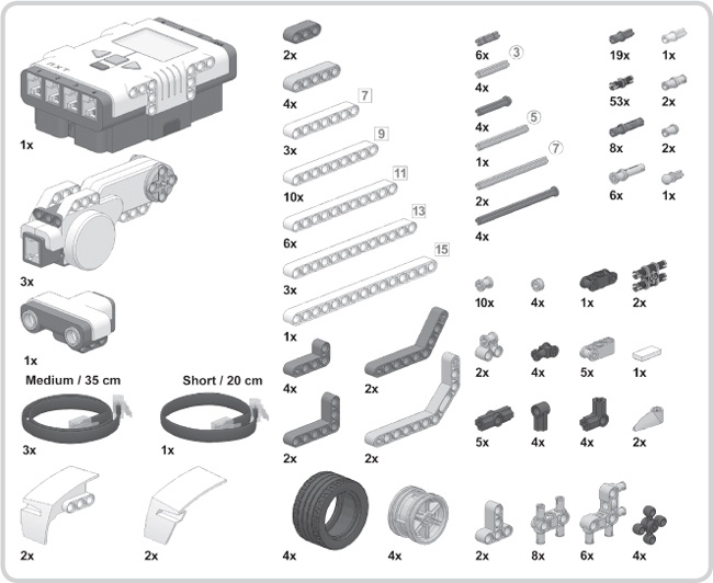
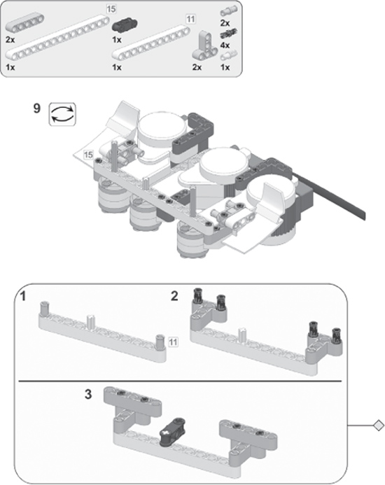
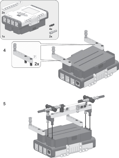
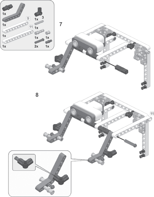
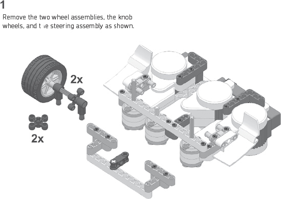
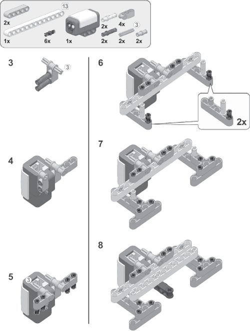
Now that you understand the Jeep’s design and how to control it, you’re ready to build it using the instructions on the following pages. You may find it helpful to pull out the required pieces beforehand using the Bill of Materials in Figure 14-5.

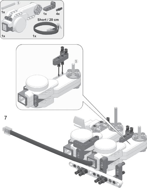
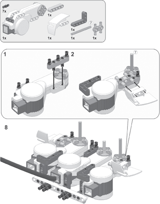


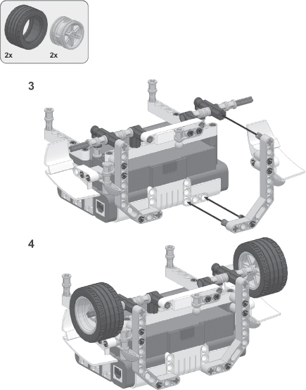
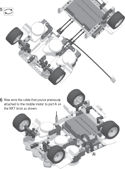


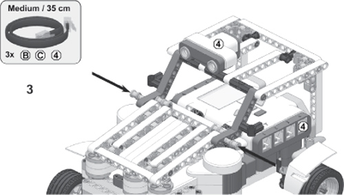
Wrap the cables around the beams as indicated by the arrows.
You don’t have to connect the cables exactly as shown. Just make sure you connect each motor to the correct motor port and guide the cables so that they do not interfere with the wheels or with the ground.

Once you’ve finished building the Jeep, you’re ready to program it. To get a better understanding of the program, read Moving Around with the Jeep’s Front-Wheel Drive.
Your first program will allow the Jeep to drive around a room while avoiding objects with its ultrasonic sensor. You created a similar program in Chapter 12, but this new program will let you control the Jeep’s movement differently. When you’re done creating the Jeep-Avoid program, you’ll program the Jeep to follow a line using a color sensor. Finally, we’ll present a few additional ideas for how to program the Jeep to park itself in an empty parking space.
You’ll include several essential aspects in every program that you write for your Jeep. First, you’ll center the middle motor (motor A) before any other action is taken. After centering, you’ll reset the rotation sensor in motor A, resulting in a reading of 0 degrees. Both steps are necessary in order to make sure that the formulas work in your programs.
Each program will also contain two sequences of programming blocks running in parallel. The blocks in the main sequence, the control sequence, define what happens in your program. Here you set the Jeep’s base speed and control its steering. The parallel sequence continuously controls the motors that power the wheels (motors B and C) using the formulas discussed earlier. The speeds are calculated based on the base speed and rotation sensor values managed by the main sequence. Figure 14-6 provides an overview of this setup.
You’ll create My Blocks to center the wheels in each of your programs for the Jeep and for the parallel sequence that powers the wheels.
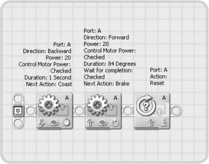
To center the steering, have the Jeep first steer all the way right and then left for precisely 84 degrees and then use a Rotation Sensor block to reset the rotation sensor in motor A. Configure the blocks that perform these actions as shown in Figure 14-7, and turn them into a My Block called Center Reset. Select appropriate icons to make it easy for you to remember the purpose of this block. (For details on creating My Blocks, see The Custom Palette.)
Here you’ll create a My Block to continuously control the front wheels. Basically, this My Block uses a series of blocks that execute the formulas for adjusting the speeds of the motors. All the blocks are in a Loop block configured to repeat forever. Follow the instructions in Figure 14-8 through Figure 14-11, and then turn the Loop block with all of its contents into a My Block called Wheel Control.
Create the program shown in Figure 14-12 to test your My Blocks. When you run the program, the Jeep should center the steering and then drive forward. Now use your hands to make the car steer left. Notice that the wheel to the right starts running faster than the other. If that’s not the case, check your program for errors. Also make sure to steer the Jeep to the right, which should cause the left wheel to run faster than the right wheel.
Note
If you make a new program for the Jeep, the basespeed variable might not be directly accessible in the Variable block. If it’s not there, redefine the variable.
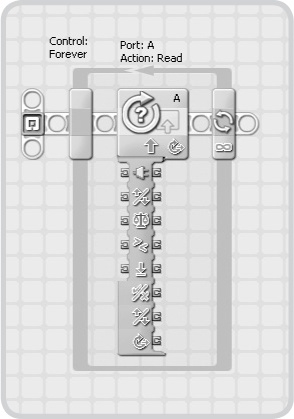
Figure 14-8. Step 1: Add a Loop block to the work area, and add a Rotation Sensor block into it. Click the tab under the block to open the complete data hub, which creates some extra space in the Loop block that you’ll use later.
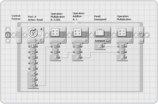
Figure 14-9. Step 2: Define a new number variable called basespeed, and then add several blocks as shown. These blocks calculate the wheel speed for the right wheel. The result plug on the rightmost Math block outputs this speed, which can be positive (wheel should turn forward) or negative (wheel should run backward).

Figure 14-10. Step 3: Now that you’ve calculated the wheel speed, you’ll add blocks that’ll make motor C turn to accomplish this wheel speed. To do so, use a Compare block to see whether the speed is positive or negative (less than 0). If it’s positive, this block outputs false, making the motor run backward, which will cause the wheel to turn forward. The calculated speed is wired into the power plug of the Motor block.

Figure 14-11. Step 4: Add the remaining blocks to the loop as shown. These blocks ensure that motor B (the left motor) will turn at the appropriate speed. Both formulas contain the multiplication of degrees by 0.006. Instead of using blocks to calculate this again, you just use an extra data wire to reuse the outcome in the formula for the second wheel.
Having programmed the Jeep’s basic controls, you’ll now expand the program to do something interesting. Instead of moving the steering with your hands, you’ll use Motor blocks to control the position of motor A. To change the Jeep’s speed, simply adjust the value of basespeed with a Variable block.
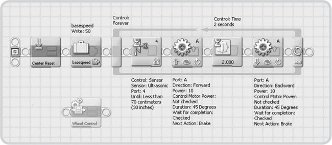
As shown in Figure 14-6, the main sequence controls the Jeep’s base speed and steering, and the Wheel Control My Block operates in the parallel sequence. In the Wall-Avoidance program that you’ll now create, the main sequence is similar to the Sentry-Avoid program (see Figure 12-2). When the ultrasonic sensor detects something, the car turns for two seconds and then continues to drive forward.
Create the Wall-Avoidance program by following the steps in Figure 14-13 and Figure 14-14. When you’re done, run the program. The Jeep should now drive around while avoiding objects.
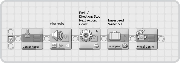
Figure 14-12. In this test program, the Jeep doesn’t control the steering, so you don’t need two parallel sequences.
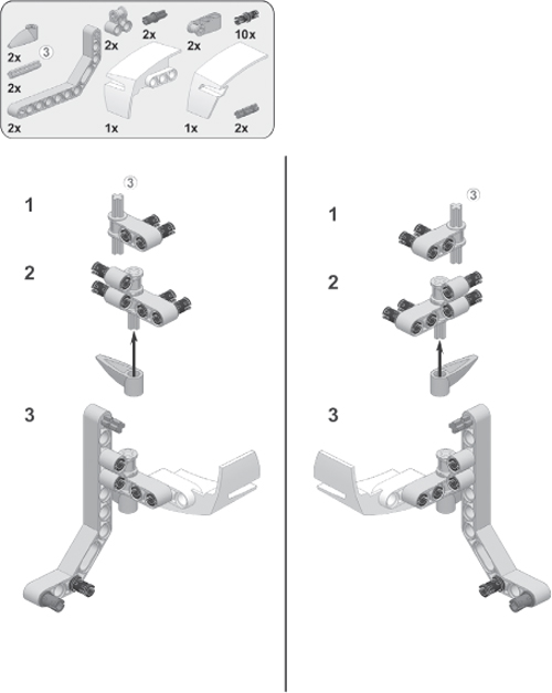
In this section, you’ll program the Jeep to follow the black line on the test pad. But first, you need to add a color sensor to the robot as shown in the following building instructions.

When following a black line on a white test pad, the robot is obviously sensing just two colors: black and white. The key to building a successful line-follower is to have the robot follow the edge of the line. If the robot senses black, it should go right until it senses white. If it senses white, it should go left until it senses black again. As long as the robot moves forward while turning left or right, it can successfully perform basic line following.
The previous description of a line-follower works well for a vehicle based on the Inventor-Bot as well as one like the Jeep. For the Jeep, however, turning left and right works a bit differently. The Jeep is turning not only when the middle motor rotates but also while the middle motor leaves the steering in any position other than centered. Also, the middle motor can turn only up to about 65 degrees in each direction.
In this program, you’ll rotate the middle motor a maximum of 60 degrees. Therefore, turning to the right until the color sensor detects white means that the middle motor should rotate until either the sensor detects white or until the maximum 60-degree limit is reached. Figure 14-15 provides an overview of the line-following program that uses this technique.
Now you’ll convert the program flow of Figure 14-15 into an NXT-G program. You’ll use the Center Reset and Wheel Control My Blocks in the same way that you used them earlier. Create the Line-Following program by referring to Figure 14-16 through Figure 14-18.
When you’re done creating the program, position the Jeep on the test pad as shown in step 11 in 10, and run the program. Once you’ve confirmed that the Jeep follows the line successfully, try modifying the program by changing the robot’s speed or adding sounds.
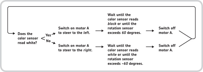
Figure 14-15. The Line-Following program repeatedly runs these commands while moving the robot forward.
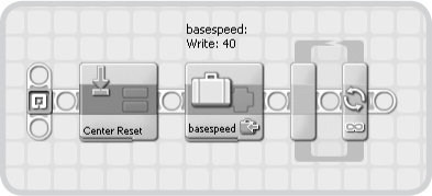
Figure 14-16. Step 1: Place the Center Reset My Block on the work area, set the base speed to 40, and add a Loop block. This loop will contain blocks that you use to follow the line.


Before you build the next robot, take some time to expand the Jeep’s design. The following are a few suggestions to get you started.
Note
If you choose to use both the ultrasonic sensor and the color sensor with your robot, remember that the color sensor’s cable may interfere with the ultrasonic sensor’s readings. To prevent this from happening, tuck the cable around the frame of the Jeep so that it won’t obstruct the ultrasonic sensor’s view.
You can make the Jeep more interactive by making it “talk” back to you with lights. To do so, remove the line-following attachment, and attach the color sensor to the car’s hood. Use the sensor as a headlight for your vehicle, showing different colors to indicate what the Jeep is seeing with the ultrasonic sensor.
Now try expanding the Wall-Avoidance program to make the color sensor emit different colors, depending on the robot’s proximity to objects. If the robot doesn’t see anything nearby, it could display a green light. Make the sensor show blue when it sees something nearby and red when the Jeep is about to crash into that something. This technique will look especially interesting when the car drives around in a dark room.
The two programs you’ve created in this chapter made the Jeep behave autonomously. Although this is certainly interesting, it’s sometimes more fun to manually control your robot with a remote control.
Connect two touch sensors to the NXT brick using long cables. Next, create a program that will make the Jeep respond to different combinations of button presses so that you can drive your Jeep around the room simply by pressing the touch sensor buttons.
Certain real cars have parking sensors, which aid drivers when parking their cars. You can use the MINDSTORMS ultrasonic sensor as a parking sensor for your Jeep to allow it to detect objects around it. You could even program the Jeep to drive into a parking lot autonomously.
To enable the Jeep to park by itself, remove the ultrasonic sensor from its current position, and add it to either the left or right side of your car, as shown in the following image. Next, create a parking lot for your robot to park in. For example, place two shoe boxes next to each other with a gap between them large enough for the Jeep to easily fit. Program the car to drive past the shoeboxes until it detects the gap, at which point it should attempt to park in the gap.
For more fun, add sounds and lights (see Idea #1: Headlights above) to tell the driver about the parking process.
You’ve just successfully built and programmed the Jeep—well done! In this chapter, you learned how to build a fourwheeled vehicle that uses its front wheels to both drive and steer. Because of the robot’s mechanical design, you didn’t simply make the robot move by powering the motors. Instead, you learned how to use simple math in an NXT-G program to effectively control and steer the robot.