So far, all the projects in this book have focused on mobile robots that use treads, wheels, or legs to get around. Now, in the final chapter, you’ll learn to build and program a stationary robot: the Printer (Figure 16-1). The Printer is a printing machine that uses a pen to write or draw on a sheet of paper. By drawing different combinations of lines, the Printer can produce basic shapes and letters.
The Printer draws lines on paper in much the same way that humans do. To draw a line, it presses a pen against a sheet of paper and moves the pen in different directions. To draw a new line in a different place, it simply lifts the pen and moves it and then repeats the process.

When drawing, the Printer can move the pen in only two possible directions, as shown in Figure 16-2: horizontally (line a) or vertically (line b). When drawing a tilted line, the Printer moves the pen both horizontally and vertically at the same time (line c). Further, when drawing vertically, the Printer actually moves the paper vertically, not the pen (that is, the paper moves vertically across the tip of the pen).
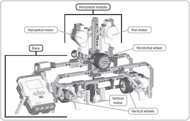
Now that you understand how the Printer can draw a line with a pen, let’s look at its components and how they work together. Figure 16-3 highlights several important sections of the machine. We’ll discuss the function of each section in turn.
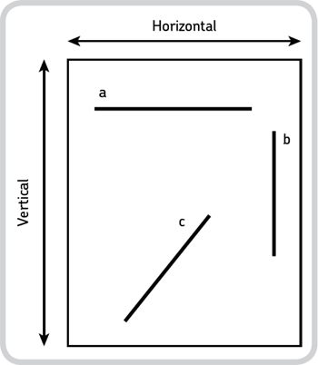
Figure 16-2. To draw a line, the Printer can move a pen horizontally (line a), vertically (line b), or in both directions (line c).
The Printer consists of two main components, or modules. The first is the base, which forms the main structure of the robot. The base holds the NXT and contains the vertical motor, which moves the paper vertically with the vertical wheels, drawing a vertical line if the motor moves when the pen touches the paper.
The base carries the second main component, the horizontal module, which moves over two racks that are part of the base. By using the horizontal motor to rotate the horizontal wheel, the complete module moves. If this motor moves when the pen touches the paper, the pen draws a horizontal line. The horizontal module also carries the pen motor, which raises and lowers the pen.
You can build the Printer with mostly the pieces from the LEGO MINDSTORMS NXT 2.0 set, but you’ll also need the following non-LEGO items. (You’ll probably have everything you need around your home.)
Paper. The Printer will work with both US letter paper (8.5 inches by 11 inches) and standard A4 paper (21 cm by 29.7 cm). If you live in North America, you’ll likely use US letter paper. If not, you’ll probably be using A4 paper. Measure your paper with a ruler to make sure you know what kind you’re using because paper size is important when building the Printer.
A pen. You can use many different kinds of writing tools with the Printer. For best results, use a marker, pen, or pencil that doesn’t require a lot of pressure to write with, such as a Sharpie fine-tip marker.
Tape. Find some tape about 1.5 cm (0.6 inches) in width, such as Scotch Magic tape (0.5 inches in width).
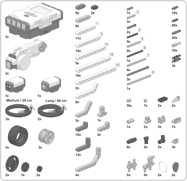
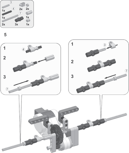
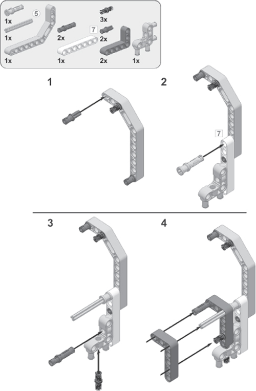
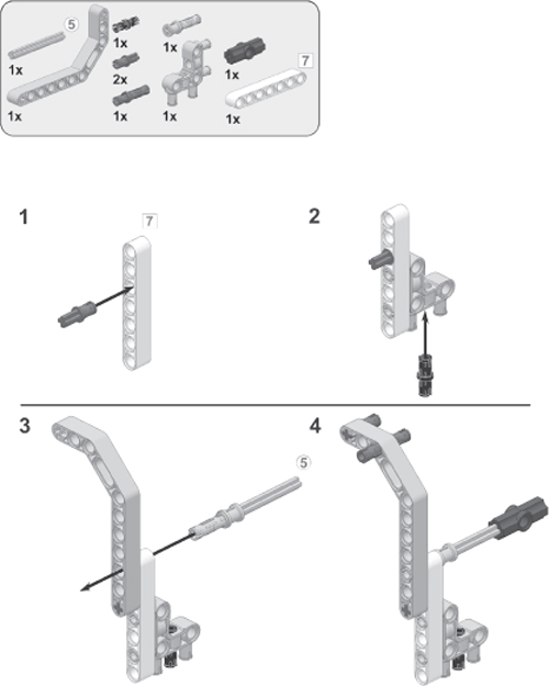
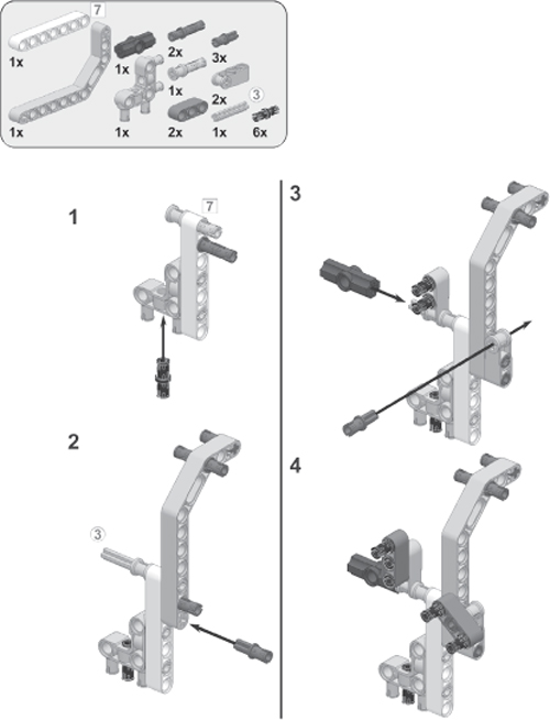
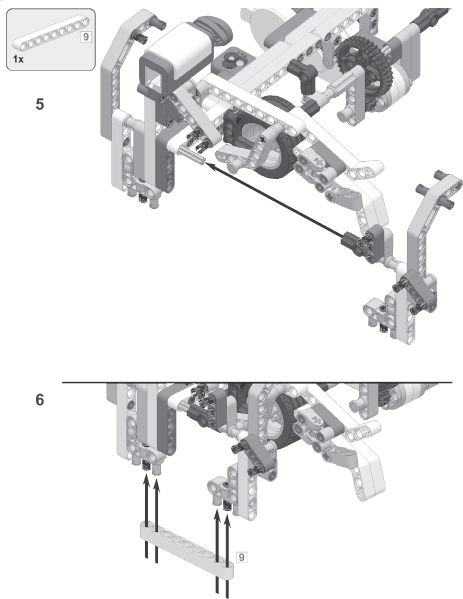
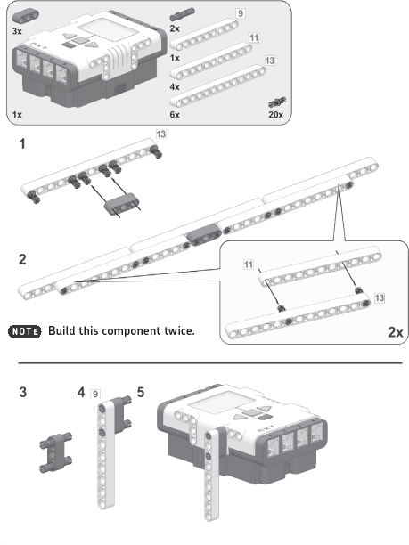
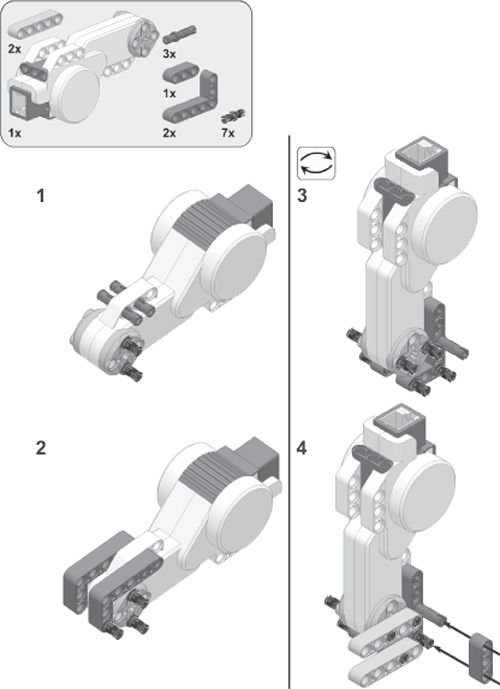
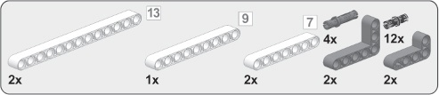
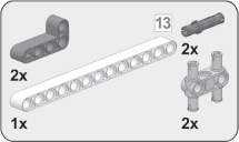
Build the Printer using the instructions on the following pages. Throughout the instructions, you’ll find comments about ways to customize your Printer. Read the notes carefully, or your robot may not work as expected. Before you begin building, select the required pieces, as shown in Figure 16-4.


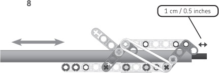
When there isn’t any paper in the Printer, the pen may accidentally write on the structure you’re currently building. To prevent this from happening, add a strip of tape as shown in step 8. The tape should be approximately 22 cm (8.5 inches) long and 1.3 to 1.5 cm (0.5 to 0.6 inches) wide. Make sure to place the tape precisely, leaving no dents in it or air bubbles under it.

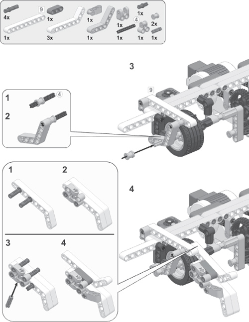
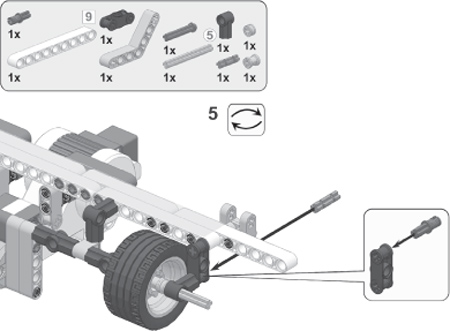
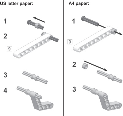
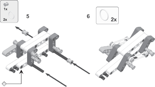
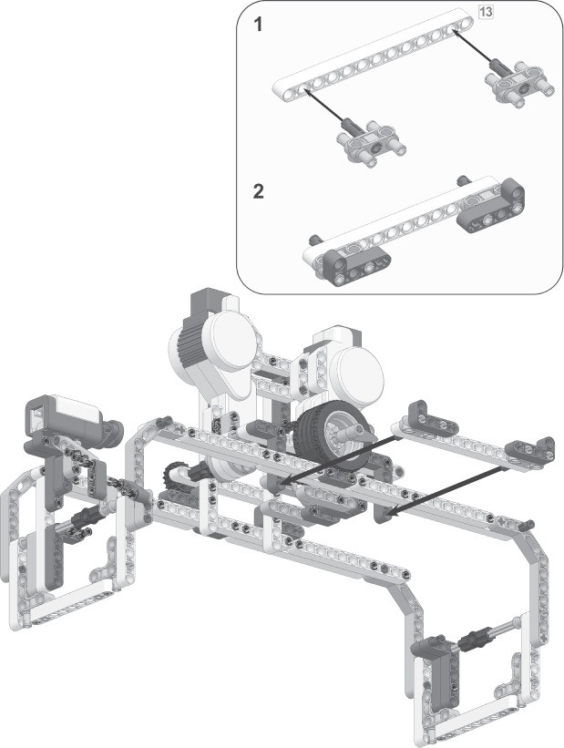
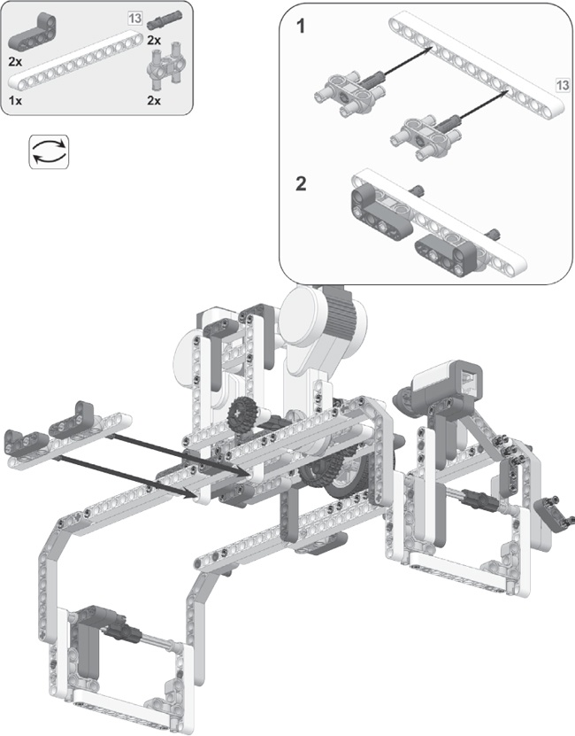
The following pieces comprise the part of the frame that will hold the paper in the Printer. Adjust your printer to the paper type you’ll be using: US letter paper or A4 paper. If you use US letter paper, follow the steps to the left, and then proceed to the next page. If you use A4 paper, follow the steps to the right, and then proceed to the next page.

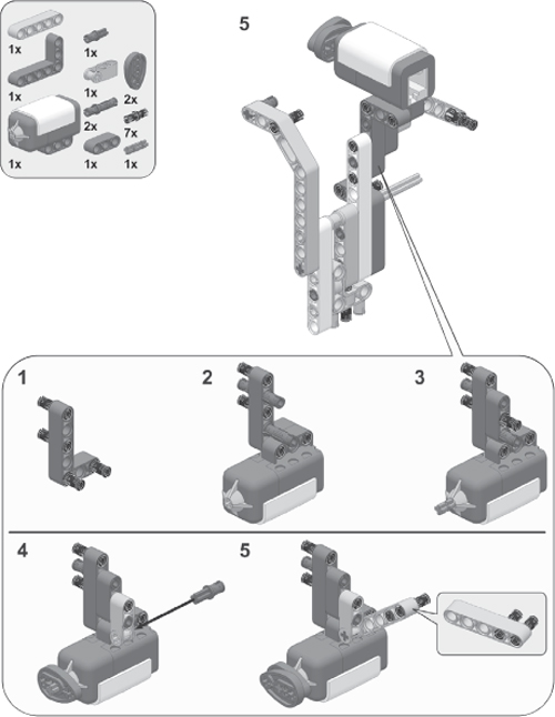


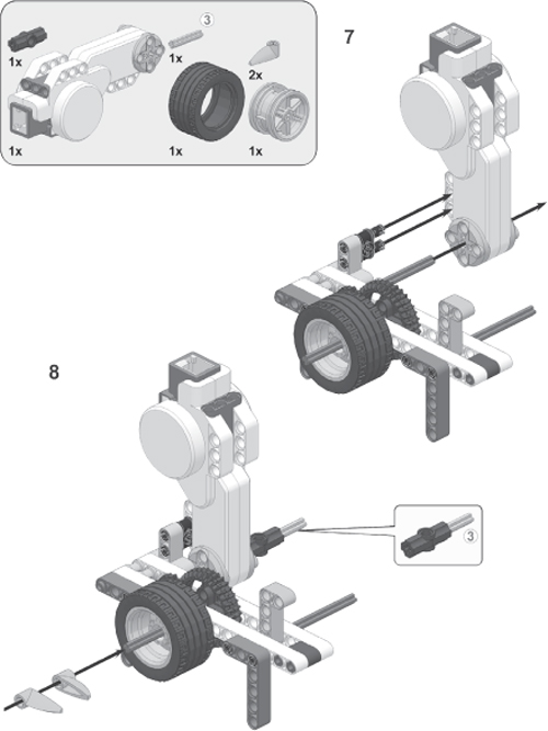

Now insert the pen that you’ve chosen into the pen holder that you just built. To do so, press the orange handle (see gray arrow), slide the pen in, and press the bushed friction pegs so that they press against the pen (see black arrows).

Next, adjust the position of the pen so that its tip sticks out of the holder by 1 cm (approximately 0.5 inches).

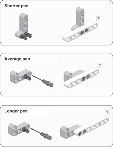
Finally, you’ll add a structure that ensures that the pen doesn’t slip out of its holder. Choose one of the three options shown here, or modify one of them to work with your pen. When you add this structure, make sure your pen tip still sticks out by approximately 1 cm (0.5 inches), as shown in step 8.


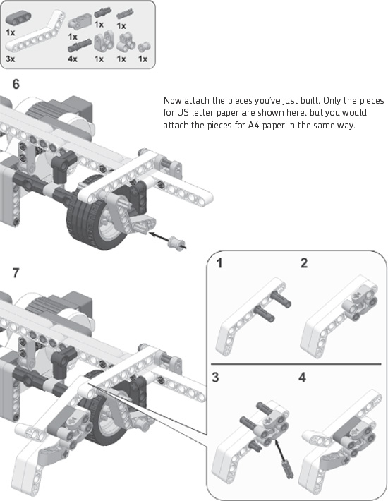
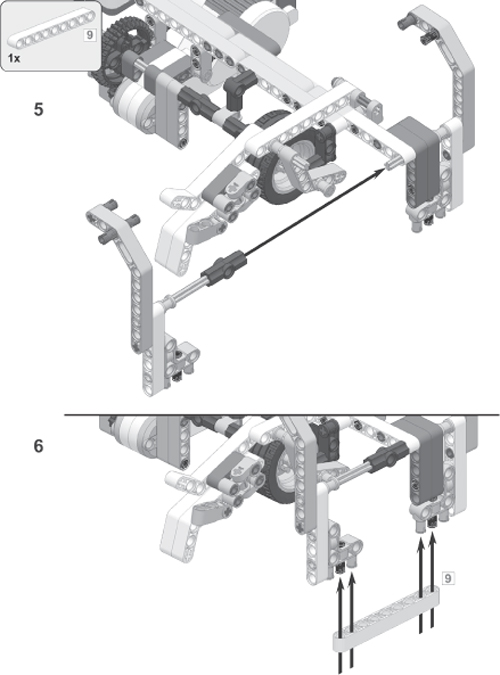
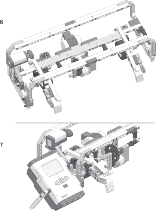
You have now completed the base and the horizontal modules. Position the horizontal module on top of the base. The two brackets that you’ll build on this page and the next will connect these two sections.
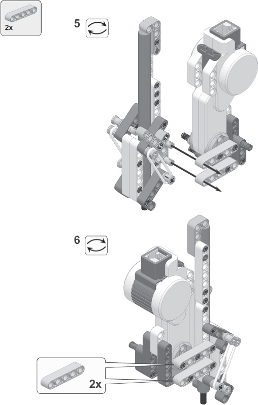
When you follow these steps, rest the base on the edge of a table so that you can easily look at the robot’s underside, as shown here. Some pieces have been hidden here to make these steps easier to follow, but you shouldn’t need to remove any pieces.
Once you’ve assembled the Printer, it’s time to connect the cables. Begin by connecting the touch sensor to input port 1 and the color sensor to input port 3 on the NXT using medium cables. Before you connect the cable to the color sensor, bend its end as shown in Figure 16-5, or your printer will lean on this cable and become unstable. Next, connect both cables as shown in Figure 16-6.
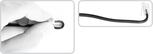

Figure 16-6. Plug the bent end into the color sensor as shown, and then plug the other end into input port 3. Next, connect the cable from the touch sensor to input port 1.
Connect the motors to the NXT as shown in Figure 16-7. Use a medium cable to connect the vertical motor to output port A, and then use the longest cables to connect the horizontal motor to port B and the pen motor to port C.

Congratulations on having built this complex machine. Next you’ll program the Printer. You’ll first create a series of My Blocks with basic functionality and then use them to create the complete program.
In Understanding How the Printer Works, you learned what actions the robot must perform in order to draw a line. In the following sections, you’ll create a My Block for each action as well as two blocks for resetting the Printer and one for ejecting the paper when the robot is finished drawing.
The first My Block, LiftPen, is a simple one. The Printer uses it to lift the pen from the paper so that it can move the pen to a different place on the paper without drawing a line as it moves. You need just one Motor block to accomplish this, but turning it into a My Block makes the action easier to perform frequently. Configure this Motor block as shown in Figure 16-8 (left side), and turn it into a My Block called LiftPen as shown in Figure 16-8 (right side). Be sure to select a few icons for this block to distinguish it from the LowerPen block you’ll make next.
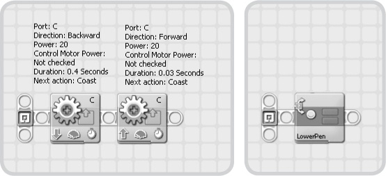
The LowerPen block lowers the pen so that it touches the paper. To do this, the block first instructs motor C to lower the pen for a certain amount of time. This action firmly presses the pen against the paper, deliberately applying too much pressure. The motor then reduces the pressure by raising the pen for a moment. Configure the blocks that perform this process as shown in Figure 16-9 (left side), and turn them into a My Block called LowerPen, selecting a few icons for the block as shown in Figure 16-9 (right side).


For accurate printing, the Printer should know where it is writing on the paper. To determine its position, the Printer always starts printing on the top left of the page and thereafter tracks its position relative to that starting point.
Now you’ll make two My Blocks that position the pen at the upper-left corner of the paper. Begin by creating the ResetHorizontal My Block, which moves the horizontal module with the pen all the way to the left of the page. The module stops moving left when it presses the touch sensor and then moves to the right slightly to release some pressure. The rotation sensor in the horizontal motor resets at this point so that the Printer knows the pen is in the starting horizontal position.
Configure the blocks to do this as shown on the left of Figure 16-10, turn them into a My Block called ResetHorizontal, and select a reset icon for it as shown on the right of Figure 16-10.
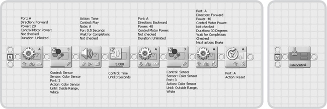
The ResetVertical My Block moves the paper in the machine so that the pen is at the top of the page. When you insert a sheet of paper into the Printer’s drawer, this My Block should move the paper into the machine until the color sensor detects white, at which point the machine knows that paper is present. Next, the block draws the paper further into the machine in order to release stress from the paper. Finally, the block pushes the paper back out a little so that the paper sits in the correct position. The rotation sensor in the vertical motor resets at this point so that the Printer knows that the sheet of paper is in the starting vertical position.
Configure the blocks to perform the previous action as shown on the left of Figure 16-11, turn them into a My Block called ResetVertical, and select a reset icon for your My Block as shown on the right of Figure 16-11.
The Eject My Block ejects the paper. It runs until the color sensor detects that the paper is no longer present, at which point the motor moves for another second to make sure that the paper is released and then stops. You place the LiftPen block inside the Eject block to make sure that the Printer won’t accidentally draw a line all the way across the paper.
Configure the blocks to perform this action as shown on the left of Figure 16-12, turn them into a My Block called Eject, and select the red stop sign for this My Block as shown on the right of Figure 16-12.

The last two My Blocks you’ll create move the pen on the paper. You can use these blocks while the pen is lowered (a line is drawn) or raised (no line is drawn).
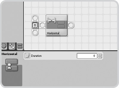
If the horizontal motor rotates forward a certain number of degrees, the horizontal module moves to the right. Running the motor in reverse will move the module to the left. You’ll create a special My Block for this action that can accept input values (an amount of degrees), allowing you to configure the block with a configuration panel. Positive values move the module to the right, and negative ones move it to the left. Create the Horizontal My Block by following the steps in Figure 16-13 to Figure 16-15.
Note
For the Motor blocks in the Horizontal and Vertical My Blocks, you’ll need to set the Duration setting to Degrees in order to configure the Wait for Completion setting.
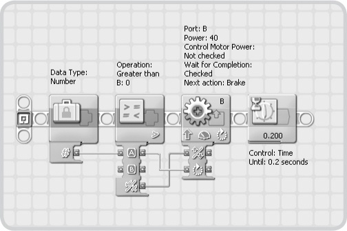
Figure 16-13. Use the Constant block to generate a data wire that acts as an input for the Compare block. The Compare block checks whether the value is greater than 0. If it is, the direction is forward; otherwise, the direction is backward. The Compare block also transfers the number of degrees to the Motor block. A Wait block at the end makes sure that the motor has fully stopped when the My Block finishes.
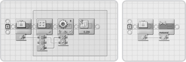
Figure 16-14. Select the latter three blocks as shown (left), and then convert them into a My Block called Horizontal. The result should be the figure shown on the right. Be sure to choose an appropriate icon for your My Block, such as the two horizontal arrows shown here (right).

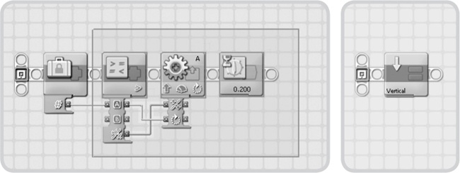
You’ll now repeat the steps from the Horizontal My Block to create a similar block called Vertical, which controls the position of the paper in the machine. A positive value pulls the paper into the Printer, and a negative one pushes the paper away from the Printer. Create the Vertical My Block now by following the steps in Figure 16-16 and Figure 16-17.
You’ve just completed the essential programming for the Printer. Before you begin drawing lines and figures, however, you should test and troubleshoot the My Blocks to be sure that you won’t run into unexpected problems.
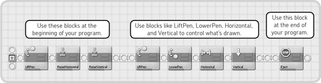
Figure 16-18 shows the basics of each program for the Printer. The first and last blocks will always be the same in your program. The blocks in the middle control what the Printer will eventually draw on paper.
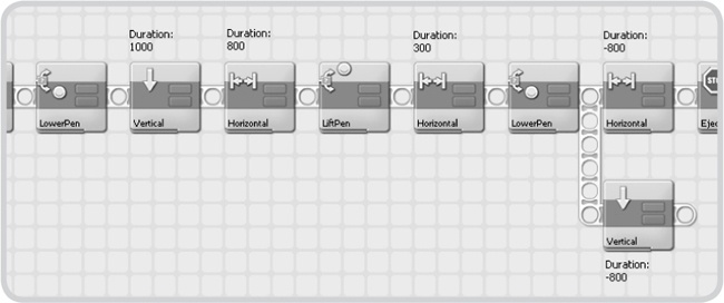
To test the My Blocks, you’ll create a program that uses each of them. See Figure 16-18 for the overall setup of your program, and see Figure 16-19 for the blocks you’ll place in the middle of your program.
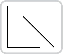
Run the program, and insert a sheet of paper into the Printer’s drawer (see Figure 16-1) when the vertical motor begins to turn. If running the test program gives a result like the one shown in Figure 16-20, skip to Creating the Final Program. If this is not the result, go to Troubleshooting the Printer.
For several reasons, the Printer may not work right the first time you use it. In fact, you will most likely need to make a few adjustments before the Printer works smoothly, so don’t be discouraged if the test program doesn’t work well. The point of the test program is to help you get the Printer running smoothly. The following are solutions to a few common problems.
Once you insert the paper into the machine and the ResetVertical My Block has finished running, the uppermost part of the sheet in the machine should lie completely flat, resting on the beam to which you’ve added a strip of tape. If the paper is not lying flat because it’s slightly crumpled or creased, the Printer won’t be able to draw properly. Use a fresh sheet of paper, or try using thinner, less stiff paper.
In some instances, the pen won’t write because not enough pressure is being applied or because it doesn’t touch the paper. If the pen sits above the paper by more than 0.5 cm (0.2 inches), check the building instructions in 7.
If the pen is close to the paper but not close enough or if not enough pressure is applied to the pen, the solution lies in the program. In the LowerPen My Block, modify the Duration setting in the first Motor block, which is currently set to 0.40 seconds. Try 0.45 seconds or longer if necessary.
The pen may press too hard on the paper, making it impossible to move the paper vertically. To fix this, see The Pen Doesn’t Write above, and change the Duration to a number less than 0.40, such as 0.35 seconds.
In areas of very bright sunlight, the color sensor cannot detect the paper sheet properly because it reads white even when no paper is present. When this occurs, the ResetVertical My Block will behave incorrectly. To fix this, move the Printer to an area with less light and try again.
Now that you’ve mastered the basic Printer controls (and ideally have it running smoothly), it’s easy to draw anything you like as long as the drawing consists of straight lines. For example, we’ll now make a drawing of the NXT logo and the text “NXT 2.0.” You can see an overview of the drawing in Figure 16-21.
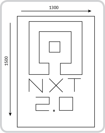
Figure 16-21. In this drawing of the NXT 2.0 logo, the arrows indicate the estimated printable area, and the numbers indicate the number of degrees required to move from one end of the printable area to the other.
The complete NXT Logo program that will print these figures is actually just a long list of My Blocks that you place one after the other. Table 16-1 lists all the blocks and their configurations. Where the table shows the words In parallel, you need to create a parallel sequence beam at that point with a single block on it (see Figure 16-19 for an example). If you’d rather not create this program manually, you can download it from this book’s companion website at http://www.nxtguide.davidjperdue.com/.
Table 16-1. The Complete List of My Blocks in the NXT Logo Program
My block Name | Duration | My block Name | Duration | ||||||
|---|---|---|---|---|---|---|---|---|---|
LiftPen | LiftPen | ||||||||
ResetHorizontal | Horizontal | -250 | |||||||
ResetVertical | LowerPen | ||||||||
Horizontal | 100 | Horizontal | 250 | In parallel: | Vertical | -250 | |||
Vertical | -100 | LiftPen | |||||||
LowerPen | Horizontal | 125 | |||||||
Horizontal | 1000 | LowerPen | |||||||
Vertical | 1000 | Horizontal | 250 | ||||||
Horizontal | -400 | Horizontal | -125 | ||||||
Vertical | -200 | Vertical | 250 | ||||||
Horizontal | 200 | LiftPen | |||||||
Vertical | -600 | ResetHorizontal | |||||||
Horizontal | -600 | Horizontal | 200 | ||||||
Vertical | 600 | Vertical | 50 | ||||||
Horizontal | 200 | LowerPen | |||||||
Vertical | 200 | Horizontal | 300 | ||||||
Horizontal | -400 | Vertical | 100 | ||||||
Vertical | -1000 | Horizontal | -300 | ||||||
LiftPen | Vertical | 100 | |||||||
Horizontal | 400 | Horizontal | 300 | ||||||
Vertical | 400 | LiftPen | |||||||
LowerPen | Horizontal | 100 | |||||||
Horizontal | 200 | LowerPen | |||||||
Vertical | 200 | Horizontal | 20 | ||||||
Horizontal | -200 | Vertical | -20 | ||||||
Vertical | -200 | Horizontal | -20 | ||||||
LiftPen | Vertical | 20 | |||||||
ResetHorizontal | LiftPen | ||||||||
Horizontal | 100 | Horizontal | 100 | ||||||
Vertical | 900 | LowerPen | |||||||
LowerPen | Vertical | -200 | |||||||
Vertical | -250 | Horizontal | 300 | ||||||
Horizontal | 250 | In parallel: | Vertical | 250 | Vertical | 200 | |||
Vertical | -250 | Horizontal | -300 | ||||||
LiftPen | Eject | ||||||||
Horizontal | 125 | ||||||||
LowerPen | |||||||||
Horizontal | 250 | In parallel: | Vertical | 250 |
Once you have your program, run it and insert a sheet of paper as you did with the test program earlier. Sit back and enjoy watching the artistic abilities of the Printer, and if you run into any problems, consult Troubleshooting the Printer.
So far, you’ve made the Printer perform preprogrammed actions. However, the machine can do much more. The following sections suggest ways to further explore this robot.
Modify the NXT Logo program to make the NXT display tell you about the printing process. Use different Display blocks throughout the program to do this, and add some sounds as well. For example, you can have the display tell you the following:
Pen’s current state: down (drawing) or up (not drawing)
Current direction of the pen’s movement
Picture/text being drawn
Time elapsed since the program started
Current percentage of the printing process completed
Expand the Printer to write pieces of Morse code. Have the horizontal motor move the pen from the left all the way to the right at a steady but slow speed. Connect a second touch sensor to the NXT, and program the robot to lower the pen as long as the sensor is pressed and to lift the pen when the touch sensor is released. Since the pen moves to the right slowly, this will create a pattern of lines. Control the touch sensor with your hand to create long and short lines.
Add an ultrasonic sensor to the Printer. Connect the sensor to the base so that it faces away from the machine. Can you create a program that will plot a graph of sensor readings over time? As with idea #2, you can make the pen move to the right at a constant slow speed. Next, all you have to do is control the position of the vertical motor based on the readings of the ultrasonic sensor.
In this chapter, you learned to build and program a stationary robot, and you saw how such a machine can mimic human movement (that is, writing or drawing) using relatively basic techniques. Although all the other projects in this book are mobile robots, this chapter demonstrates that stationary robots can be exciting and challenging as well.
You also learned how to construct a robot from several modules, each with its own function. When integrated into one design, the modules combine their functionality to accomplish a single complex function: writing. You used the modular concept not only while building the Printer but also while programming the Printer by combining various My Blocks to create a single, larger program.
You’ve reached the end of this book, but this doesn’t have to be the end of your journey in robotics. Use Appendix C to find many excellent online resources for further study, but as always, the best way to learn how to do something is to try it for yourself. You’ll definitely want to use the robots in this book for ideas, but eventually you’ll want to put everything away except the set and just dive in and start building something completely new. And really, that’s where the fun begins.