7
chains and pulleys
Transferring torque with LEGO pieces is possible not only with gears and axles but also with two additional systems: pulleys and chains. All of these systems work with similar principles.
LEGO pulleys are wheels that can be connected via strings or rubber bands, allowing for the transfer of drive and movement. You’ve seen similar pulleys in “belt” systems in real life. Pins without friction, bushes, and other circular elements can also be used as LEGO pulleys. A pulley system is particularly useful for lighter loads, transferring drive silently and over a long distance.
LEGO chains work similarly, though they’re better suited for higher torque than a pulley. A chain replaces the rubber band of a pulley system, and gears replace the pulleys. The driver gear in a chain is known as a sprocket, just as in a tracked vehicle. Instead of being held by the frictional force of a string or rubber band, a chain is held by meshing its links with gears. Figure 7-1 shows the pulley and chain systems side by side.
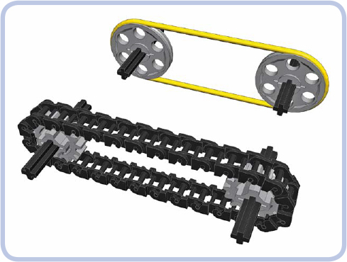
Figure 7-1: Two pulleys with a rubber band (yellow) and two gears with a chain (black). The two systems share the same working principles.
Since the chain system is less versatile and therefore simpler, we are going to discuss it first. Then we will move to pulley systems and configuration. Keep in mind that the same configurations are possible for chain and pulley systems, though they’re often more practical with pulleys.
chains
The LEGO chain system has been present in the Technic line since 1979, and despite its rarity, it’s unlikely to go out of use. The chain consists of small, rigid links that can be connected so that every link can be tilted relative to the next one (see Figure 7-2). In this way, we can create a flexible but rigid chain of any length, which can be wrapped around gears. Figure 7-3 shows the size of the LEGO chain compared to a 1×2 brick. You may also recognize the chain link as similar to the LEGO track link (see Figure 7-4), which is used for tracked vehicles.

Figure 7-2: A single chain link and a section of four connected links, shown with slots facing upward and downward. In theory, the chain is less likely to come apart when its slots face the gear, but in practice, the difference is negligible.

Figure 7-3: An individual chain link is very small and practically impossible to combine with any other type of LEGO piece.

Figure 7-4: The chain link (left) is similar to the LEGO track link (right) and can be combined with it. To learn more about tracks, see Chapter 18.

Figure 7-5: All the chain-compatible gears
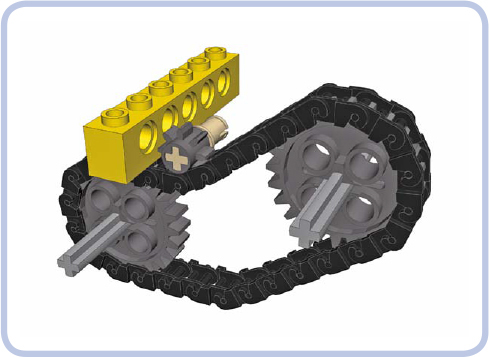
Figure 7-6: The 8-tooth gear also works with a chain but cannot drive it due to the gear’s small size. It can still be used as an idler gear, adapting the shape of the chain to the surrounding structure.
Five different gears work with the chain, as shown in Figure 7-5. While the 8-tooth gear can work with the chain, too, it cannot drive the chain as it’s simply too small (see Figure 7-6). Also note that by using the 24-tooth gear with clutch, you can make a chain slide when its output is stopped (for example, under load), meaning that the chain will behave just like a rubber band would over pulleys. Chains can also be wrapped around turntables to drive them, but they are rarely used this way as there are other, much less space-consuming methods of driving a turntable (for example, with a worm gear or an 8-tooth gear).
Even though the chain is rigid, it has a degree of elasticity because the links are made of thin material. This allows us to adjust the tension of the chain. In general, the chain should not be very tight, as a tight chain is more likely to come apart under torque. Some play in the chain is therefore desired. The section of the chain that makes contact with the gear has no play; rather, the play of a chain accumulates between the gears, usually in the lowest section of the chain due to gravity (see Figure 7-7). This play allows the system to withstand more force and becomes a problem only when it’s large enough to decrease the chain’s area of contact with the gears, increasing the risk of links skipping their teeth, or when it’s large enough to come in contact with the structure around the chain, where it can catch. When dealing with chains longer than 20 links, it’s a good idea to add 1 extra link just to lower the tension. Soft shock absorbers can be used to add a bit of tension.
The chain can be used to change the gear ratio by simply connecting two gears of different sizes. Linking two gears via a chain works exactly like directly meshing them: The gear ratio is equal to the number of follower gear’s teeth divided by the number of driver gear’s teeth. For instance, by using a chain to drive a 24-tooth gear with a 16-tooth gear, we obtain a 16:24 ratio, which can be reduced to 1:1.5, just as in a direct connection. And in the same way, the ratio of a chain system is not affected by idler gears. The only difference is that the chain keeps all the gears it’s wrapped around rotating in the same direction, with the exception of idler gears that are located outside the chain rather than inside it (see the idler gear in Figure 7-6). Note that you can use one chain to drive several follower gears of various sizes, creating a different ratio for each of them.
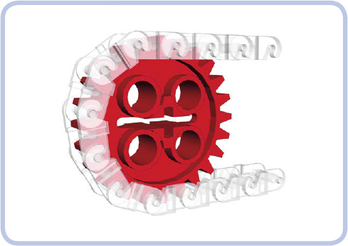
Figure 7-7: A close-up view of the chain wrapped around a gear shows that each link occupies two teeth. The section of the chain that has contact with the gear has no play in it, and its elasticity is minimized.
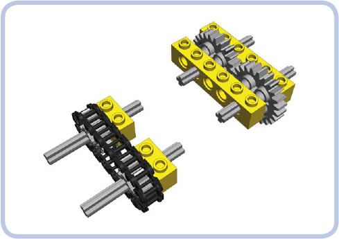
Figure 7-8: One major advantage of a chain (left) is that it does not require reinforced structure around it to handle high torque, unlike gears meshed directly (right).
The important characteristic of a chain is its behavior under torque. When a high torque is applied to gears meshed directly (shown at left in Figure 7-8), it pushes them apart, which may cause their teeth to skip. But when a high torque is applied to gears connected with a chain, it pulls them together. This means that a chain has an advantage in high-torque applications: Gears connected with a chain don’t need a reinforced housing—the chain is something of a structural reinforcement itself.
pulleys
Pulleys are circular LEGO pieces designed to work with rubber bands or strings. They are distinguished by a groove around the rim, and there are only four types, as shown in Figure 7-9. Other LEGO pieces can be used as pulleys, too, but without a groove, they don’t hold rubber bands or strings as securely. Note that many wheels without tires can also be used as pulleys.
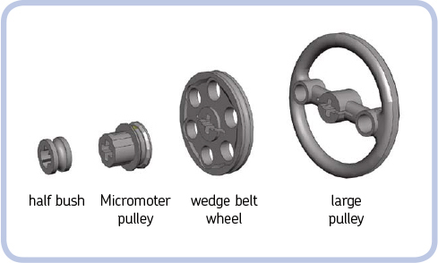
Figure 7-9: All four LEGO pulleys
The two most common pulleys are the regular half bush and the wedge belt wheel (so named because of its resemblance to real-life wheels designed to work with wedge belts, which we replace with rubber bands). The large pulley is less common, and the Micromotor pulley is the rarest, as it was originally meant to be used only with the LEGO Micromotor. When we connect two pulleys with a rubber band or a string, we create a gear ratio between them, just as we do in a chain system. The ratio depends on the proportion of their driver and follower diameters, which are shown in Figure 7-10. By driving a wedge belt wheel with a half bush, for example, we get a 21:5.8 ratio, which is equal to 3.6:1. And by driving a Micromotor pulley with a large pulley, we get a 9:32 ratio, which is equal to 1:3.55.
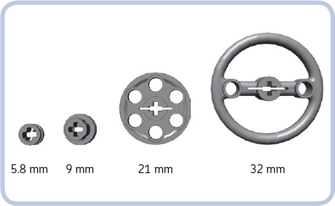
Figure 7-10: The diameters of the pulleys, which determine their ratios
However, ratios between pulleys are less reliable than ratios between gears because there is no solid connection between driver and follower, just an elastic rubber band or a string that can slip, extend, or retract under load, thus altering the ratio. We can actually use this lack of a solid connection to our advantage—for instance, such slippage could prevent a motor from stalling. The diameter-based calculation should, therefore, be considered just an approximate value. The effective ratio depends on a number of factors, including the torque transferred and the tension of the element connecting the pulleys, and it varies rather than staying at one fixed value.
Using pulleys with strings is the subject of the next section. For now, we will focus on rubber bands. It’s perfectly possible to use any kind of thin rubber band, but the LEGO Group actually produces its own rubber bands, which work noticeably better. The rubber bands found in Technic sets are made of a high-quality silicone that rarely breaks and stays elastic for years, and their round cross section fits pulleys’ grooves better than the square cross section of ordinary rubber bands.
The pulley-dedicated LEGO rubber bands come in five sizes, from a 2×2-stud band to a 7×7-stud band. Other than their size and color, the bands are identical, and each of them can be stretched to a larger size, with the bigger bands able to stretch more than the smaller ones. The various bands and their most popular colors are shown in Figure 7-11.
The general behavior of two pulleys connected with a rubber band is very similar to that of two gears connected with a chain: The rubber band acts as a belt, keeping all the pulleys inside it rotating in the same direction. Its shape can be changed with idler pulleys, and it pulls pulleys together when subjected to high torque. One band can also be used to drive several follower pulleys of various sizes by a single driver pulley, effectively creating a different ratio for each of them.
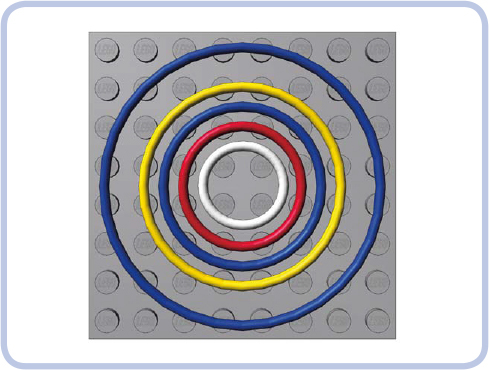
Figure 7-11: LEGO rubber bands come in five sizes, with diameters of 2, 3, 4, 5, and 7 studs. This figure also shows the most common color for each size.
The main difference between rubber band and chain drive systems is that the rubber band should be as tight as possible, because any play can stop it from transferring drive or even make it fall off the pulleys. Slippage in a pulley system isn’t entirely negative—the fact that a band can slip when the follower pulley is stopped or blocked eliminates the need for a clutch of any kind. Note that when tight enough, the LEGO rubber bands can transfer surprisingly high torque without slipping, although they are generally considered less reliable than gears in high-torque applications. One problem is that bands are more likely to break, which can be disastrous when dealing with high torque.
Another advantage of pulley systems is their small size and thickness. The two most common pulleys—the half bush and the wedge belt wheel—are only a half stud thick, allowing two pairs of pulleys to fit where only one pair of gears would, as shown in Figure 7-12. That makes them a better choice than gears when space is limited and torque is low. Moreover, as long as the bands don’t slip, they create practically no backlash, regardless of their number, which is a huge advantage over gears in mechanisms that need to react quickly and accurately. Finally, they are practically noiseless.
Also note that the band is more flexible than the chain and can be bent in any direction, allowing you to create mechanisms that are just not possible with a chain, such as pulleys that can be driven at an angle (see Figure 7-13).
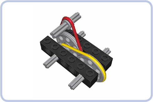
Figure 7-12: Two pairs of pulleys can fit into a 1-stud-wide space, which would be filled entirely by a single pair of gears.
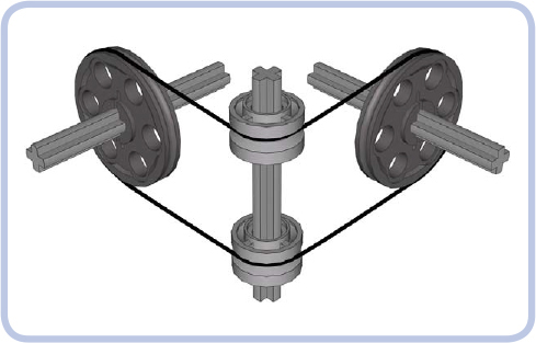
Figure 7-13: Two pulleys are connected by a rubber band at an angle, with two freely rotating rims on a vertical axle used as idlers to guide the band.
string and pulley systems
Using pulleys with strings is different from using pulleys with rubber bands. You can, of course, tie string into a loop and wrap it around two pulleys, but it won’t work as well because it won’t be as tight as a rubber band—string is simply less elastic and has much less grip. While rubber bands are used to transfer drive between two or more pulleys, string is best used to transfer the actual movement, that is, the displacement itself.
A perfect example of such a system is a winch in a crane, where string is wound on a reel and rotating the reel makes it pull loads up and down through a system of pulleys, as shown in Figure 7-14. In this case, the reel is the driver, and the movement is transferred to the hook at the end of the string. Without pulleys, the reel would have to be located on top of the crane, directly above the load. With pulleys, the string can be guided from the top of the crane to the back of it, where the reel is easily accessible and acts as the crane’s counterweight.
There are numerous examples of mechanisms using string to transfer movement, including drawbridges, window blinds, and even cable railcars (where a car literally attaches to and detaches from a moving cable to travel). However, pulleys can do more than guide movement.
Pulleys and string can be combined into systems that realize mechanical advantage. Mechanical advantage is a measure that shows how much a given mechanism amplifies the force we apply to it. For example, a mechanical advantage of 2 means that the force is amplified twice. This is exactly the kind of speed/torque transformation we have discussed when dealing with gears, and mechanical advantage is simply another way of describing a ratio. So, a mechanical advantage of 2 is simply a ratio of 2:1.
The idea of mechanical advantage is well illustrated by the crane example from Figure 7-14. Let’s assume that we have already installed in the crane a system of pulleys that grants us a mechanical advantage of 2. This simply means that we have to apply half the force for twice as long—and that’s because amplification of the force comes at the cost of the extra length of string to wind up. For example, to lift a 100 g load 1 m, we have to rotate the reel long enough to wind up 2 m of string using only enough force to lift 50 g. Trading torque for speed works to our advantage because how much we can lift is usually more important than how fast we can lift it. With enough mechanical advantage, we can lift or move any load, no matter how heavy—its weight affects only the amount of time it will take. (Obviously, it also requires a structure strong enough to support it.)

Figure 7-14: A simple crane uses a winch to pull a load on a hook up and down. The movement is transferred through a string, which is guided from the reel to the top of the crane by two half bushes acting as idler pulleys.
Pulley systems that realize mechanical advantage are usually installed just between the top of a crane and its hook. The invention of such pulley systems is attributed to ancient Greeks, and the systems were refined by ancient Romans. It is estimated today that the most advanced Roman cranes allowed a single person to lift up to 3 tons of load, which is quite impressive for simple machines made mostly of wood. This load capacity could be multiplied by using a number of cranes together to handle a single load. Many of the ancient buildings we admire today could not have been created without this invention that allowed human power to move extremely heavy objects.
A pulley system typically consists of at least one pulley that is fixed above the load and stays in place—for example, on the top of our crane—and at least one pulley that moves together with the load—for example, by being attached to the hook of our crane, as shown in Figure 7-15. So, there are two groups of pulleys, one fixed and another moving, and each can consist of many pulleys.
The way the two groups of pulleys are connected with string and how many times they are connected determines the mechanical advantage they provide. There are three categories of pulley systems, each with groups of pulleys connected in different ways, and we will discuss them starting with the simplest one.
simple pulley system
The simplest pulley system consists of two groups that are identical. The upper group is the fixed one. The string goes over the upper group’s first pulley and then comes down to the lower group, which is moving, and wraps around the lower group’s first pulley. Then it comes back to the upper group and is tied to it, or it can be wrapped around a second pulley and repeat the arrangement between the first two pulleys. This means that the string can’t be tied directly to the hook after it comes from the first upper pulley, which is the main difference between the simplest pulley system and the lack of any such system, as Figures 7-16 and 7-17 show.
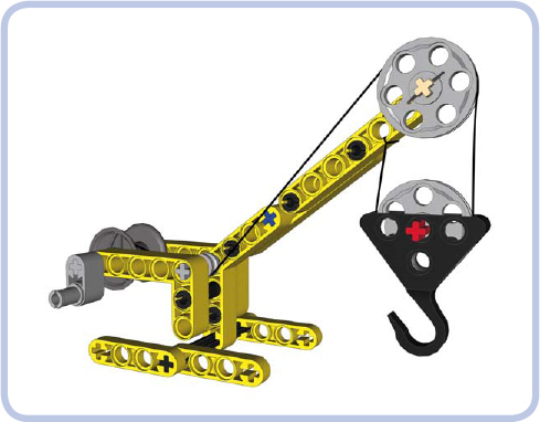
Figure 7-15: Our simple crane equipped with a pulley system. Two groups of pulleys are used, each consisting of a single pulley: The upper one stays on top of the crane, and the lower one moves up and down with the hook. This particular arrangement of string between the pulleys grants a mechanical advantage of 2.
As you can see in Figure 7-17, the simplest pulley system has two sections of string connecting the two groups. This means that in order to lift the load, we have to wind up twice as much string as without this system, but using only half the force. There’s no free lunch: We are trading time for work, having to do less work but over a longer period of time.
But let’s consider what happens if we add another section of string between the two groups. We will need one more pulley to prevent the sections from getting tangled up with one another, as shown in Figure 7-18.
As you see, the string is now tied to the lower group, but only after it goes through three pulleys: two upper ones and one lower one. Three sections of string connect the two groups, granting a mechanical advantage of 3. We need to wind up three times as much string but use only one third of the force. By now you have probably guessed that the number of sections of string connecting the groups determines the mechanical advantage they realize.
These simple pulley systems are commonly used in sailboats and have various names depending on how many sections of string connect the two blocks. The system with two sections is called a gun tackle, and the system with three sections is called a luff tackle. Other systems, shown in Figures 7-19 to 7-21, have up to six sections of string. As the number of sections increases, the whole system becomes less and less efficient, as each pulley creates additional friction and the significant length of string in the whole system is prone to stretching under load.
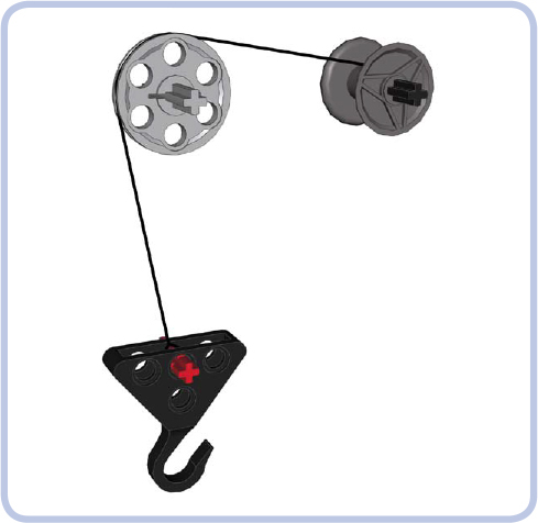
Figure 7-16: This arrangement has an upper group with a single pulley and no lower group. The string that comes off the pulley is tied directly to the hook. No pulley system is created, and no mechanical advantage is gained.
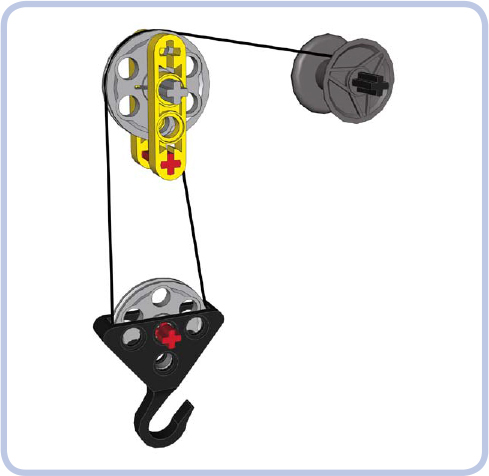
Figure 7-17: This arrangement, called a gun tackle, has two groups, each with a single pulley. The string comes off the upper pulley and around the lower pulley. It is then tied to the element that is part of the upper group and remains fixed to it. This is the simplest pulley system, with a mechanical advantage of 2.
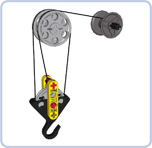
Figure 7-18: A pulley system with three sections of string between the groups, called a luff tackle. The upper group has string coming through it twice and hence two pulleys to prevent the string from getting tangled up. The string is then tied to the red axle in the lower group. This arrangement grants a mechanical advantage of 3.
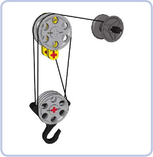
Figure 7-19: This system, called double tackle, grants a mechanical advantage of 4.
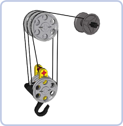
Figure 7-20: This system, called gyn tackle, grants a mechanical advantage of 5.
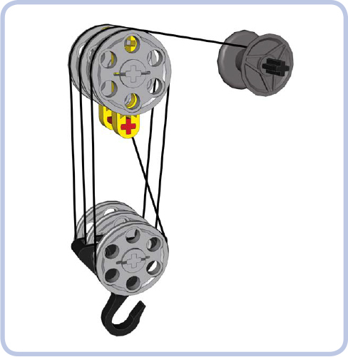
Figure 7-21: This system, called threefold purchase, grants a mechanical advantage of 6.
differential pulley system
Despite its name, the differential pulley system (also known as the Chinese windlass) does not use a differential gear. Instead, it uses an upper group with two different-sized pulleys rotating on the same axle, as shown in Figure 7-22. The string is arranged so the rotation unwinds it from one pulley while winding it on the other. The mechanical advantage is determined by the size difference of the pulleys and is greatest when the size difference is smallest. In fact, differential pulleys can achieve an extremely high mechanical advantage, far surpassing that of any other pulley systems. They are also safer to operate because the weight of the load can’t unwind the string from the upper pulley. When a regular pulley is released while the load is midair (for example, when you disconnect it from a motor or simply let go of its crank), the load will unwind the string from the upper pulley and drop down. In a differential pulley system, the load pulls on both ends of the string, which are wound onto two coaxial pulleys from opposite sides. Thus, if a differential pulley is released, the load stays right where it is.
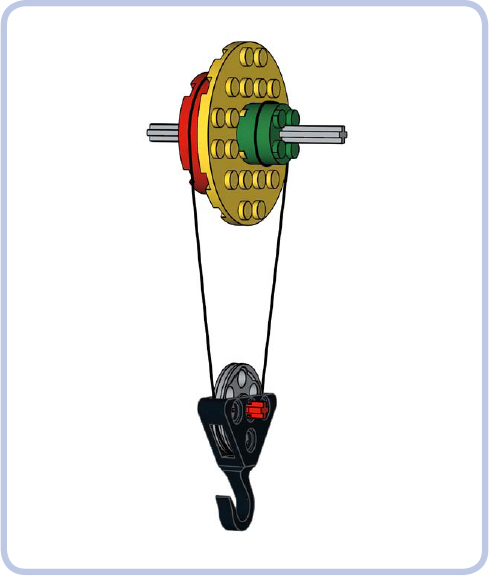
Figure 7-22: A differential pulley system producing a mechanical advantage equal to 4
If R is the radius of a large upper pulley and r is the radius of a small upper pulley, the mechanical advantage of the differential pulley is equal to (2 × R) / (R − r).
In Figure 7-22, R is 16 mm (2 studs) and r is 8 mm (1 stud), which gives a mechanical advantage equal to 32 / 8, which is 4. Using this formula, you can see that the mechanical advantage is bigger if the difference in the upper pulleys’ sizes is very small. For example, if the smaller pulley had a radius of 1.5 studs (12 mm), the entire system would produce an advantage of 32 / 4, which is 8.
Note that the formula remains true regardless of the unit of measure used. You can simply use studs, which in the example in Figure 7-22 would be (2 × 2) / (2 − 1) = 4 / 1 = 4.
Keep four details in mind when you’re building a differential pulley:
![]() Because you’re winding and unwinding a string, it’s best to use reels or drums rather than pulleys. Smooth, round pieces of a fixed diameter, such as round bricks, are the best choice because you can combine several of them to obtain a reel of your desired width. Just don’t forget to fasten the end of the string to them!
Because you’re winding and unwinding a string, it’s best to use reels or drums rather than pulleys. Smooth, round pieces of a fixed diameter, such as round bricks, are the best choice because you can combine several of them to obtain a reel of your desired width. Just don’t forget to fasten the end of the string to them!
![]() Make sure you store some reserve of the string on the reels. Because the string is wound and unwound at varying rates, the amount of string in reserve limits the reach of the differential pulley: At some point, you’ll simply run out of string.
Make sure you store some reserve of the string on the reels. Because the string is wound and unwound at varying rates, the amount of string in reserve limits the reach of the differential pulley: At some point, you’ll simply run out of string.
![]() It’s important to prevent the string from skipping from one reel onto the other. In Figure 7-22, the yellow round plate acts as a simple separator. The larger and smoother the separator, the lower the risk of the string winding up on it. In this example, the string could catch on one of the yellow plate’s studs.
It’s important to prevent the string from skipping from one reel onto the other. In Figure 7-22, the yellow round plate acts as a simple separator. The larger and smoother the separator, the lower the risk of the string winding up on it. In this example, the string could catch on one of the yellow plate’s studs.
![]() Because the mechanical advantage depends on the relative radius of the reels, it can be affected by the amount of string on the reels. Make sure the extra layers of string don’t make the reels equal in diameter, as this would effectively stop the pulley.
Because the mechanical advantage depends on the relative radius of the reels, it can be affected by the amount of string on the reels. Make sure the extra layers of string don’t make the reels equal in diameter, as this would effectively stop the pulley.
power pulley system
The power pulley system is the most complex and most effective of the three systems. It’s distinguished by having one upper group and several lower groups that are connected in series, with the hook attached to the last one, as shown in Figure 7-23.
As you see, this system starts with one section of the string (black) coming off the reel, going through the upper pulley, going through the pulley of the first lower group, and then being tied to part of the upper group. Then the lower group has another section of string (green) attached to it.
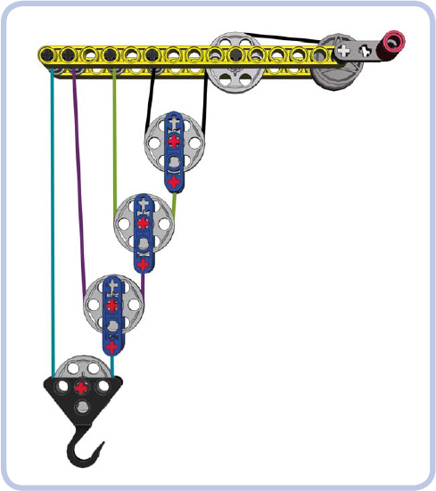
Figure 7-23: The power pulley system consists of one upper group and a number of moving lower groups connected in series. There are four lower groups here, granting a mechanical advantage of 16.
This string goes through the pulley of a second lower group and is then tied to part of the upper group, just like the first string’s section. This series can continue until the final lower group, which has a hook attached to it and handles the actual load. In Figure 7-23, the hook is present on the 4th lower group, but it could just as well be present on the 20th one. Note that by moving the points where strings are tied to the upper group away from its pulley (to the left in Figure 7-23), it’s possible to make the lower groups travel not only up and down but also forward and backward.
The mechanical advantage of the power pulley system is equal to 2n, where n is the total number of lower groups. This means that the mechanical advantage increases rapidly with the number of lower groups, starting with 2 for one group, 4 for two groups, 8 for three groups, 16 for four groups, and so on. This may not sound impressive compared to the 22 we achieved with the differential pulley system, until you realize that the advantage in the power system exceeds 1,000 with 10 lower groups and 1 million with 20. And there is no technical limit on how many lower groups can be used, although just like the other systems, this one becomes inefficient with many pulleys adding friction and a lot of string stretching under load.