19
transmissions
Just like their real-life counterparts, LEGO transmissions are mechanisms capable of changing their internal gear ratio. They can increase gear reduction in the drivetrain when more torque is needed and decrease it when speed is of greater importance. It’s the same principle at play when shifting gears in a car or in a bicycle, and this ability makes LEGO electric motors much more versatile.
A typical transmission has a number of fixed gear ratios, one of which can be selected at a time. Such a gear ratio is often simply called a speed or a gear: We can shift to lower gear (increasing the gear reduction) or to higher gear (decreasing the gear reduction). Therefore, a transmission must have at least 2 gears (as shown in Figure 19-1), while some of the most complex ones can have more than 10. Depending on their number of gear ratios, we call them 2-speed transmissions, 3-speed transmissions, and so on.
A transmission usually has a single input and a single output; the input is connected to the drive motor, and the output is connected to the final drive (wheels or tracks). A typical transmission also houses a number of gears, and each speed uses only a few of them. In other words, while some of the gears are used to transfer the drive and affect the current gear ratio, other gears just rotate unused. This makes them work like idler gears: driven but idle. In transmissions, they are called dead gears, and the fewer their number, the more efficient the transmission, as they add weight and therefore friction.
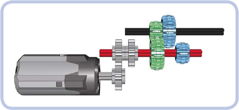
Figure 19-1: The inside of a simple 2-speed transmission. Consider what happens if we move the red axle 1 stud to the left and the green gears disengage and blue gears engage, changing the gear ratio between the motor and the output axle.
Lastly, we’ll consider a special type of transmission called a distribution or split transmission. This type of transmission has one input but several outputs. Such a transmission allows several mechanisms to be driven by a single motor without interfering with each other, as only one mechanism is driven at a time. We will discuss this particular type of transmission at the end of this chapter; for now, let’s focus on the simpler ones.
types of transmissions
When it comes to transmissions, we can organize our models into several categories. Firstly and most importantly, a transmission can be synchronized or nonsynchronized. This refers to how easy it is to make gears mesh while shifting gears. Whenever a gear is shifted, one pair of gears has to disengage, and another pair has to engage. In synchronized transmissions, gears can engage at any speed and any position; in nonsynchronized transmissions, engagement is a matter of making the gears’ teeth meet properly, which can succeed or fail, depending on the gears’ positions and on the difference of their speeds. If gears fail to engage properly, they grind their teeth, and we have to try to shift the gear again. We can assume that gears will always engage in synchronized transmissions; in nonsynchronized ones, successful shifting is a matter of the shape of the gears’ teeth, the speed of shifting, and a degree of luck. Some types of gears mesh more easily than others in nonsynchronized transmissions. For example, double-bevel gears, because they are beveled, engage more easily than typical spur gears. Naturally, it’s much easier to shift a nonsynchronized transmission while its input is stopped; in a synchronized transmission, it makes no difference.
Secondly, transmissions can be categorized as sequential or regular. Sequential (or linear) transmissions can only be shifted from one gear to the next closest one. That is, they can be shifted from 2nd to 3rd gear, but they can’t be shifted from 2nd to 4th gear directly; instead, they have to shift from 2nd to 3rd and then to 4th. Regular (or nonlinear) transmissions, on the other hand, are not bound by this restriction, and they often use elaborate shift sticks, like the one in Figure 19-2. They can shift even from 10th to 1st gear directly, even though it may be dangerous to change the gear ratio so much so quickly. In real life, sequential transmissions are common in bicycles and motorbikes, while regular ones are found in cars.
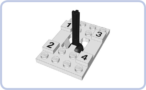
Figure 19-2: The unique shift stick from the 8880 set, the first LEGO set with a nonlinear and synchronized transmission. The transmission has 4 speeds, and the stick can move in an H pattern, allowing it to shift from one gear to any other.
how LEGO transmission driving rings work
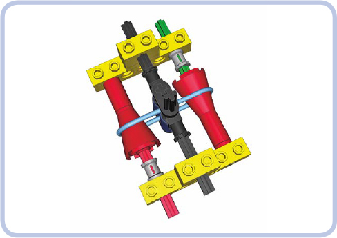
Building a synchronized transmission with regular pieces is quite difficult, but LEGO has developed a special piece just for this task. It’s called a transmission driving ring and is shown in Figure 19-3.
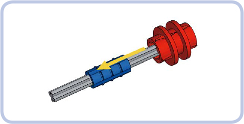
Figure 19-3: The transmission driving ring (red) must be placed over an axle joiner (blue). The axle joiner connects two axles that each go 1 stud deep inside it.
Once the transmission driving ring is placed on an axle joiner, the two pieces will rotate together; at the same time, the ring can slide forward or backward along the joiner. You can use a ribbed joiner if you want the ring to need some force to slide, thus preventing it from sliding accidentally, or a smooth joiner if you want it to slide easily (see Figure 19-4). Figure 19-5 shows what happens when you put two 16-tooth gears with clutches on the axle next to the ring. The gears rotate freely on the axle unless they’re engaged by the driving ring that slides into them.
The easiest way to control the transmission driving ring is to use another special piece called the transmission changeover catch, shown in Figure 19-6. It was developed specifically to move the ring back and forth, engaging and disengaging it with the adjacent gears. The catch should be located above the ring on a separate transverse axle.
Figure 19-7 shows a very simple 2-speed transmission that uses a driving ring controlled with a catch. If you engage the ring with the gear to its left (as shown in the middle), the resulting gear ratio will be 3:1. If you engage the ring with the gear to its right (as shown on the bottom), the resulting gear ratio will be 1:1. The key to understanding how this mechanism works is to remember that 16-tooth gears with clutches rotate freely on axles unless they’re engaged with the driving ring. Therefore, they can be used to transmit drive over the axle they sit on without driving that axle or any other gears on it.
The main advantage of the transmission driving ring is that it can engage at any moment, at any speed, and without needing to stop the input axle. The main disadvantage is that it works only with 16-tooth gears, so additional gears are needed just to achieve various gear ratios, resulting in a number of dead gears.
WARNING The transmission driving ring is also a torque-sensitive piece; it can disengage itself or even get physically damaged if a large torque is applied to it. This makes nonsynchronized transmissions a more common choice for high-torque applications.
Figure 19-4: A ribbed 2L axle joiner (blue) and a smooth 2L axle joiner (green) both work with a driving ring; the smooth joiner makes operating the driving ring easier, which may be helpful in remotely shifted transmissions.

Figure 19-5: The three positions possible for a transmission driving ring are engaged with left gear (top), neutral (middle, no gears engaged), and engaged with right gear (bottom). Note that only engaged gears rotate in unison with the axle.
Figure 19-6: The transmission driving ring and the transmission changeover catch. Note that the catch rotates together with the axle it sits on, but it can slide along it freely. Some transmissions use this property to let a single catch control several adjacent rings. To see an animation of this process, visit http://bricksafe.com/files/blakbird/Technicopedia/animations/driving.gif.

Figure 19-7: A simple 2-speed synchronized transmission set in neutral gear (top), low gear (middle), and high gear (bottom)
If you want to experiment with complex synchronized transmissions, it’s difficult to go beyond four speeds without using an extension driving ring, shown in Figure 19-8. It works like an overlay for the regular transmission driving ring, allowing it to engage placed gears 1 stud away from it, as shown in Figure 19-9.
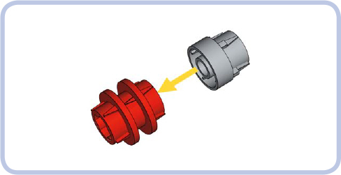
Figure 19-8: The extension driving ring (light grey) can be placed over the transmission driving ring (red) to extend it by 1 stud. Note that there is a large backlash between the driving ring and the gear it engages through extension.

Figure 19-9: The driving ring engaging a gear directly (top), disengaging (middle), and engaging a gear via the extension (bottom). Note that the extension doesn’t slide with the driving ring but acts like a part of the gear and rotates together with it.
Because it’s 2 studs long, the driving ring is poorly suited for studless constructions, which favor pieces in odd lengths. That’s the reason LEGO introduced a newer variant of the transmission driving ring in 2015, shown in Figure 19-10, which is 3 studs long instead of 2. Other than that, it’s nearly identical to the earlier ring. With it came two new 3L axle joiners: a smooth one and a ribbed one (also in Figure 19-10) and a double-sided 16-tooth gear with a clutch (see Figure 19-11). Note that the 3L axle joiner has 1-stud-deep axle holes on either end and a solid 1-stud-long section in the middle.

Figure 19-10: The old 2L (red) driving ring is meant to work with 2L axle joiners and the new 3L (dark grey) driving ring is meant to work with 3L axle joiners. You can swap the joiners, but the rings won’t work well with the wrong joiners. Note that both 2L and 3L axle joiners come in two variants: smooth (red, left) and ribbed (white, right).
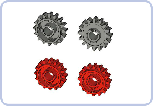
Figure 19-11: The old 16-tooth clutch gears (top) have one side with a clutch (top left) and one without a clutch (top right). The new 16-tooth clutch gears (bottom) have two identical sides with a clutch.

Figure 19-12: Two types of driving rings (2L on top, 3L on bottom) along with all the pieces they’re compatible with. Notably, the 2L driving ring won’t engage with double-sided 16-tooth gears with a clutch.
The new pieces are very similar to the old ones and were created to make things easier rather than to create new possibilities. The new 16-tooth gear with clutch no longer has a “right” and “wrong” side, for example. It will work no matter which side is facing the driving ring, whereas the older gear was a common source of building errors. Similarly, the 3L driving ring doesn’t make new transmission designs possible; it’s just much simpler to use with studless constructions (whereas the 2L driving ring is better suited for studded constructions). Note that the shape of the 3L ring’s teeth is different from that of the 2L ring and appears to be optimized to lower the risk of disengaging under stress.
However, there’s an interesting distinction between the rings: The 3L ring works with old 16-tooth gears, but the 2L ring can’t work with the new 16-tooth gears. It simply won’t engage with them. Figure 19-12 shows pieces compatible with each ring type.
transmission designs
This section lists a number of designs for complete transmissions. For each design, there is the type of transmission, a short description, and a scheme showing which gears are active at which speed. Building instructions for selected transmissions appear at the end of the chapter.
The following colors are used to mark pieces: green for the input axle, red for the output axle, and light blue for the active gears. The changeover catches are removed for clarity.
Keep in mind that it’s also possible to combine two or more transmissions of any type by making one transmission’s output another one’s input. The number of speeds will be effectively multiplied: For example, a 2-speed transmission combined with a 4-speed one will produce 8 speeds.
Some builders like to include a reverse gear in their transmissions. This is accurate in relation to real transmission systems but redundant when used with an electric motor that can be reversed at any moment. I have omitted such designs on purpose because I think they waste a potentially useful speed for no good reason.
Many builders consider a sequential synchronized transmission the best variant of all because it can be easily shifted remotely. While beyond the scope of this book, such a transmission relies on a control mechanism that is independent of the actual transmission and that can be used with many of the designs shown below. For ideas on creating remote-controlled transmissions, check out the website of Sheepo, one of the best LEGO transmission builders: http://www.sheepo.es/.
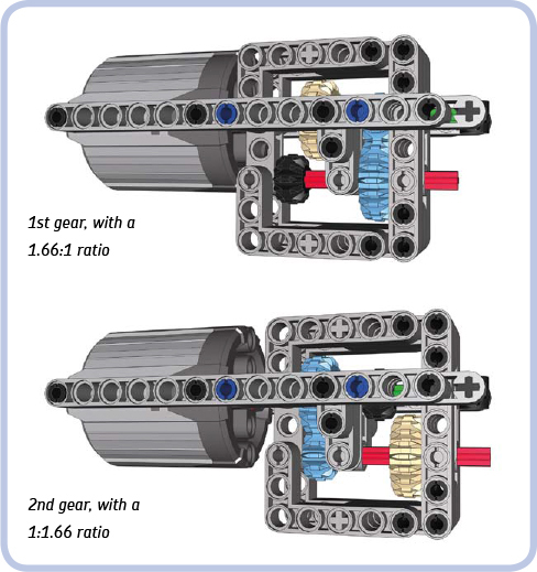
2-speed synchronized transmission
Type: sequential, synchronized

This is the simplest synchronized transmission possible. (Building instructions are on page 311.)
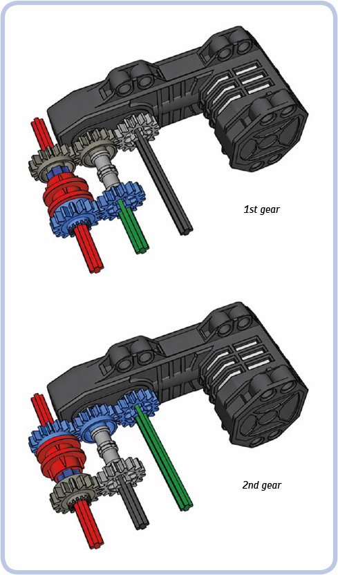
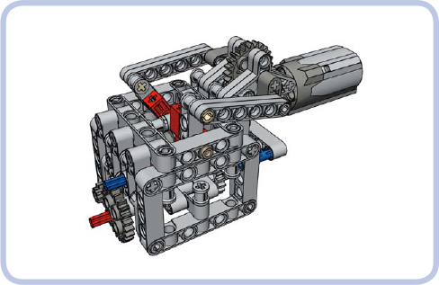
2-speed linear heavy-duty transmission
Type: sequential, nonsynchronized
A transmission designed specifically to handle high torque, shown here with the PF XL motor. Gears are shifted by sliding part of the transmission together with the motor attached to it. This makes the transmission simpler and reduces the number of gears.
Building instructions are on page 312.
2-speed RC motor transmission
Type: sequential, synchronized
This unusual transmission can be built with one or two RC motors. LEGO RC motors have two outputs instead of one, with the outer output having 26 percent more torque and less speed than the inner output. This transmission is connected to both of the motor’s outputs at the same time, allowing us to select which one drives it. This allows us to make use of the difference in the outputs’ properties, even though the gear ratio of the transmission itself is 1:1 at both speeds.
Building instructions are on page 314.
2-speed orbital transmission
Type: sequential, synchronized
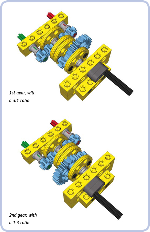
This transmission is placed between two gears and shifted by rotating it 180 degrees. In this example, rotation is done with a dark grey crank that should be blocked once rotated. You can use a worm gear to rotate and then block the transmission. The transmission is synchronized without using the transmission driving ring and provides a vast difference in gear ratios. Additionally, it has no dead gears.
Note the half bushes used to create a gap between the transmission and the bricks on its sides. The gap is intended to prevent the 4L axles on the sides of the transmission from getting into the holes in the bricks and blocking the transmission.
Building instructions are on page 316.
2-speed ratchet transmission
Type: sequential, synchronized

This transmission uses a ratchet to shift gears. It shifts when the direction of the motor that drives it changes. It’s small, simple, and synchronized without the use of the transmission driving ring. It can handle significant torque, but its output always rotates in the same direction, regardless of its input direction. So when it’s used in a car, it makes the car drive only forward or only backward.
The transmission works like this: The direction of the input tilts the ratchet left or right. A 16-tooth gear on top of the transmission meshes with one of two 12-tooth double-bevel gears when the ratchet is tilted. The 16-tooth gear sits on an axle pin with friction, and the resistance created this way makes the ratchet press hard against the 12-tooth double-bevel gears. The greater torque is handled by the transmission. The greater the resistance on the ratchet, the harder it presses, meshing its top gear more effectively. There is, of course, a limit to how much torque can be handled.
Building instructions are on page 317.
3-speed linear transmission
Type: sequential, nonsynchronized

This transmission is simple but large. It uses an extendable driveshaft to make the input driven and movable at the same time. The control lever is shown semitransparent for clarity.
Building instructions are on page 318.
4-speed double-lever transmission
Type: regular, nonsynchronized
This regular transmission is strong and useful. It’s very simple and relatively small, but it has two control levers, which is challenging when it comes to remote control. It consists of three shafts connecting input and output: one fixed and two that can slide by 1 stud. Due to its simplicity, no building instructions are provided, just the schemes of its speeds. The control levers are shown semitransparent for clarity.
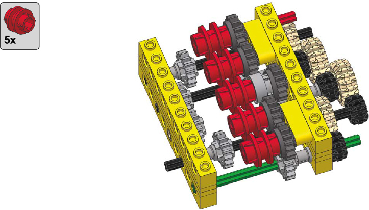
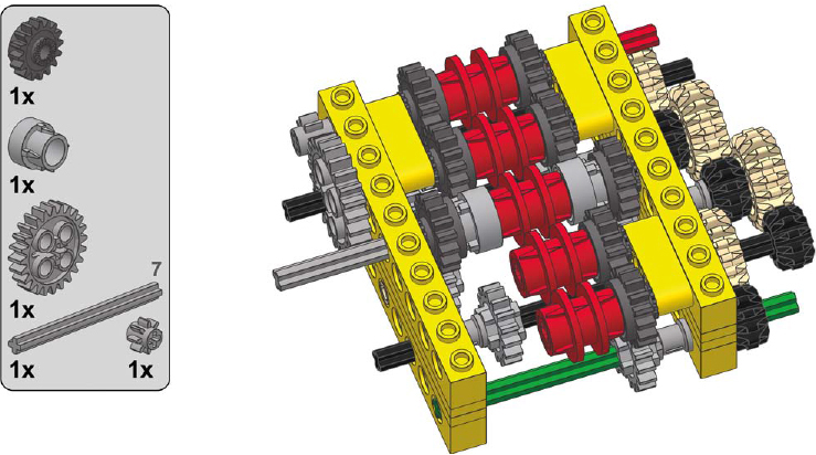
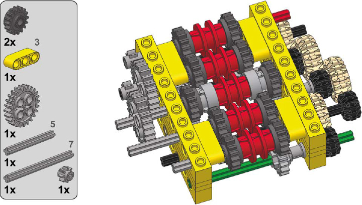
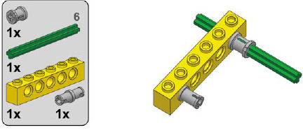
4-speed synchronized transmission
Type: regular, synchronized
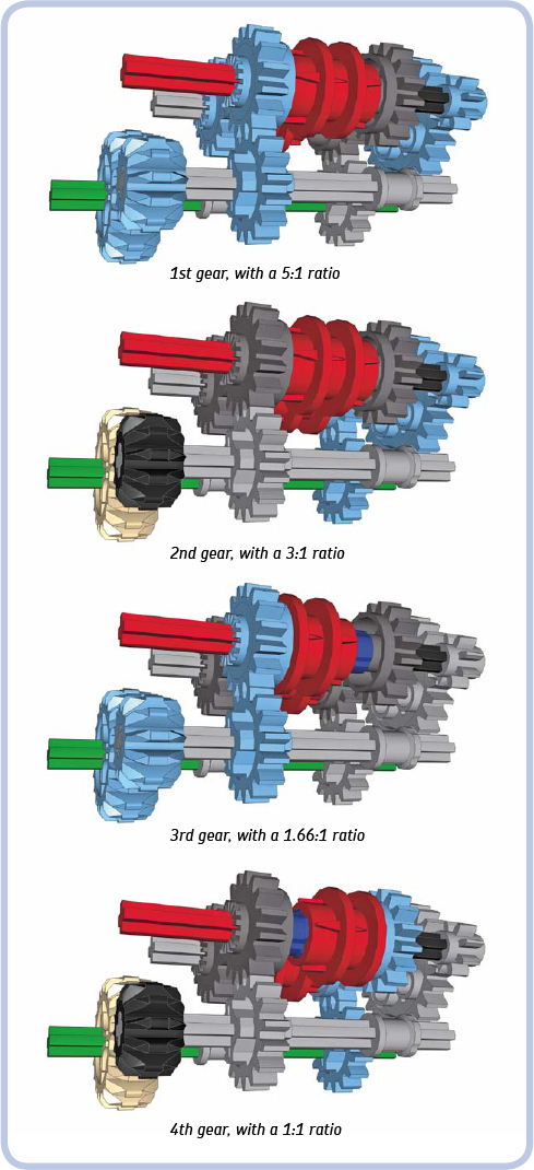
NOTE The structural parts and the control levers have been removed for clarity.
This synchronized transmission, shown in Figures 19-13 to 19-15, has two transmission driving rings, only one of which should be engaged at a time. Relatively small and providing a large difference in gear ratios, it can be controlled by a single lever moving in an H pattern or by two levers, one for each driving ring. It has a lot of dead and idler gears.
Building instructions are on page 320.
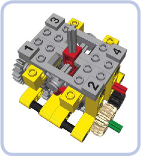
Figure 19-13: The 4-speed synchronized transmission with a single control lever moving in an H pattern. Note the special so-called “changeover plates” (light grey) used to control the shifting lever’s movement and to support the axle it moves along.
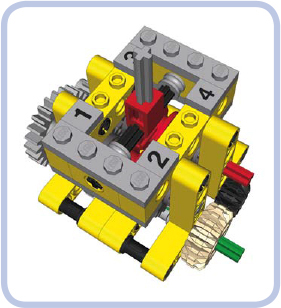
Figure 19-14: The 4-speed synchronized transmission with a single control lever moving in an H pattern. The lever is housed and supported by common LEGO pieces.
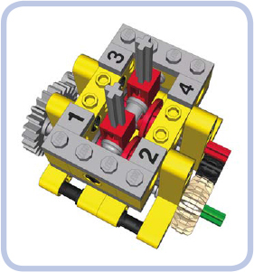
Figure 19-15: The 4-speed synchronized transmission with two control levers, each controlling a single transmission driving ring. Note that both rings can’t be engaged at the same time: one has to be set in neutral position before the other one is engaged.
4-speed sequential RC synchronized transmission
Type: sequential, synchronized
This variation of the regular 4-speed synchronized transmission includes a control mechanism that uses a single motor. This effectively turns it into a sequential transmission that can be shifted remotely and shifts in an endless loop from 1st to 4th gear and back again. For example, if you start at 1st and continue shifting up, you’ll go through 2nd, 3rd, and 4th gears and then back to 1st again. If you start at 1st and continue shifting down, you’ll go through 4th, 3rd, and 2nd gears and then back to 1st again. Because one of the two driving rings is always engaged, this transmission has no neutral gear.
This 4-speed synchronized transmission is heavily reinforced and can withstand significant torque due to the use of a worm gear, which keeps the driving rings engaged. In fact, it’s the most complete and practical transmission you’ll find in this book. Once I developed it, I pretty much stopped using any other designs.
But there’s one crucial requirement for using this transmission: For the transmission to shift, one driving ring must disengage and the other must engage. If both rings become engaged accidentally, the transmission will lock up. To avoid such an incident, use your ear while shifting: The driving rings produce a distinctive “click” sound while shifting. Therefore, you need to hear two clicks to know that the transmission has shifted properly. This is why it is not recommended to use this transmission with smooth axle joiners inside the rings, as that will eliminate any sounds while shifting.
This design was optimized for the new, 3L driving rings, but it can be easily converted for use with the older versions by adding half-stud-thick beams on the sides. Note that the blue axle marks the input and the red axle marks the output.
Building instructions are on page 321.
5-speed linear transmission
Type: sequential, nonsynchronized

This transmission has one central shaft that can slide by 4 studs. Its disadvantage is that the central shaft makes use of a rare 16L axle, which can bend and disengage gears under high torque. Due to its simplicity, no building instructions are provided here, just the schemes of its speeds. The control lever is shown semitransparent for clarity.
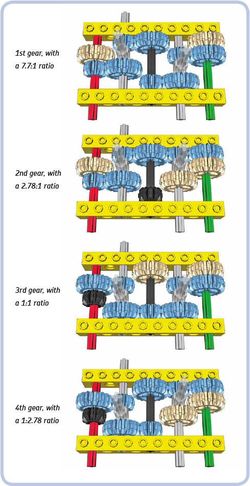
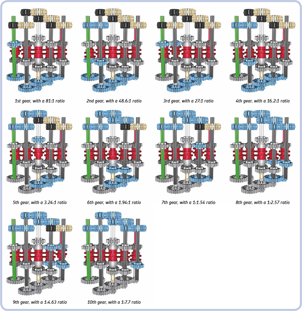
10-speed synchronized transmission
Type: regular, synchronized
NOTE This is the bottom view with the structural parts and the control levers removed for clarity.
This transmission has a 4-speed design that’s expanded further with the use of extension transmission driving rings. If you study it closely, you’ll notice that it can be expanded beyond 10 speeds by adding another pair of extensions and then four regular transmission driving rings. You can continue to expand it beyond this point by again adding two extension driving rings and so on. There’s no limit to how many speeds can be added this way, except that the number of dead gears in the transmission increases quickly and a 14-speed version generates enough resistance to stall a PF XL motor. (Building instructions are on page 326.)
continuously variable transmission
Type: sequential, synchronized
The continuously variable transmission (CVT) is a special type of a transmission. It doesn’t have a definite number of speeds with fixed gear ratios. Instead, it has a minimum and maximum ratio, and it can be shifted continuously between them.
Real-life CVTs are very useful, but at the same time, they are very complex and often based on hydraulics or magnets. The easiest way to build a CVT with LEGO pieces is by using cones and a rubber band.
As you see, the transmission consists of input and output shafts with opposing cones connected by a rubber band. The band can be moved left or right so that it’s wrapped around the broader portion of one cone and the narrower portion of the other. The circumference of the each cone is 22 mm at its narrowest and 50 mm at its broadest, which corresponds to a 1:2.27 ratio. This transmission can therefore be shifted smoothly between ratios 1:2.27 and 2.27:1.
The transmission can’t handle much torque, and the tension of the rubber band has to be adjusted carefully in order for it to work properly. Too little tension will make the rubber band slip; too much tension can displace the cones. The original LEGO rubber bands work best as they are sticky and have a round profile; they come in many variants of different lengths that can work better or worse depending on the distance between the shafts in the transmission. Also note that the control lever module is mounted between two 1×2 bricks with axle holes. Axle holes not only keep the control lever straight. They also add some resistance so that it takes force to move the lever and thus the lever can’t be moved by the rubber band’s tension.
Building instructions are on page 331.
distribution transmissions
One type of transmission’s primary function isn’t to change gear ratios but to change which output is driven at the moment. This transmission, the distribution transmission, can be synchronized or not, depending on whether transmission driving rings are used. Distribution transmissions are very useful whenever there is a need for one motor to control one of many functions at a time, and they are quite popular in LEGO Technic sets.
In most cases, the distribution transmissions themselves are fairly simple; it’s transferring the drive from them to several receiving mechanisms that can be tricky. Figures 19-16 to 19-20 present a few examples of such transmissions with various numbers of outputs, shown without housing for clarity. Note that the examples have a 1:1 ratio on all outputs for simplicity, but it’s possible to create various ratios on various outputs.
Figure 19-16: A nonsynchronized distribution transmission with two outputs
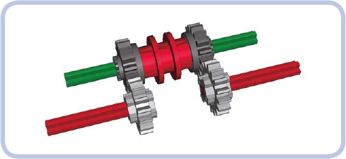
Figure 19-17: A synchronized distribution transmission with two outputs
Figure 19-18: A synchronized distribution transmission with four outputs
Figure 19-19: A synchronized distribution transmission with six outputs
Figure 19-20: A synchronized distribution transmission with eight outputs
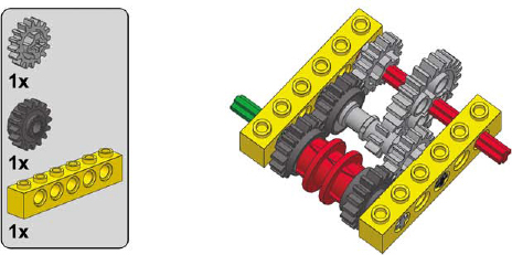
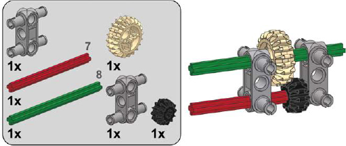
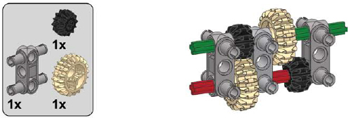
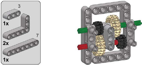
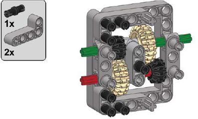
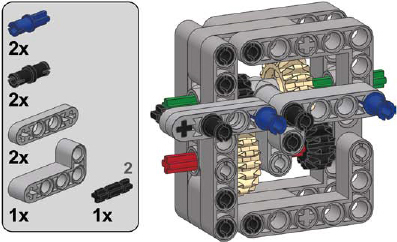
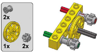
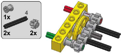
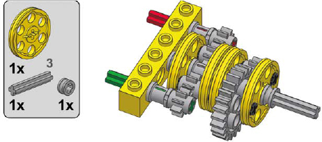
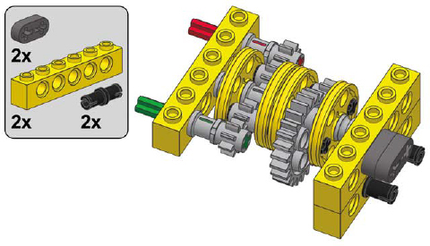
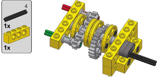
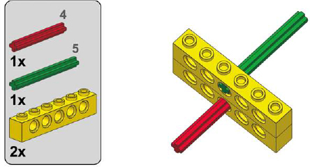
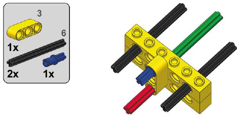
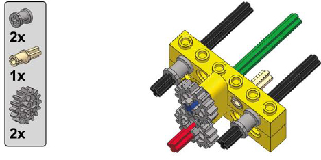
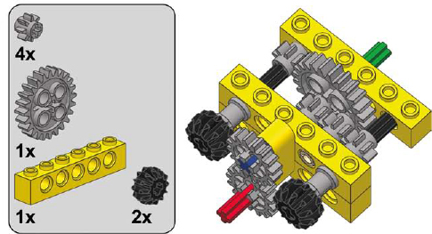
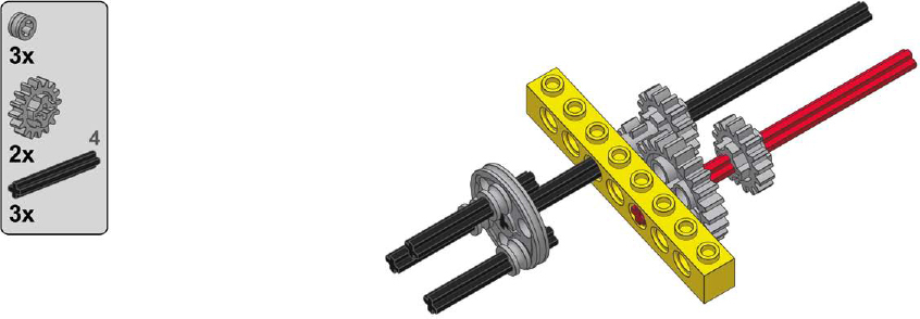
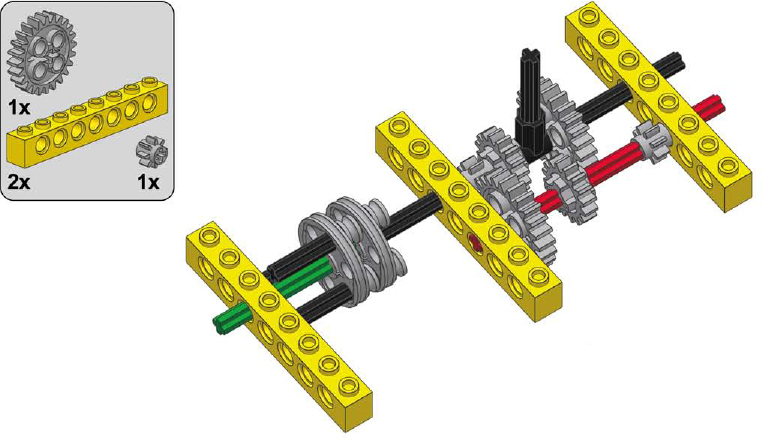
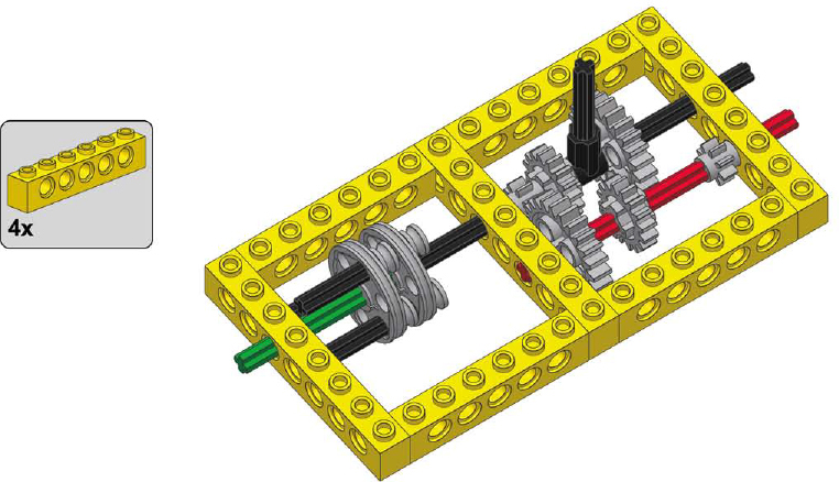
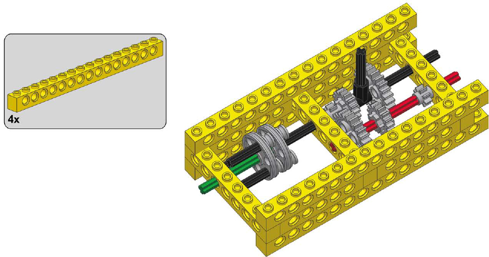
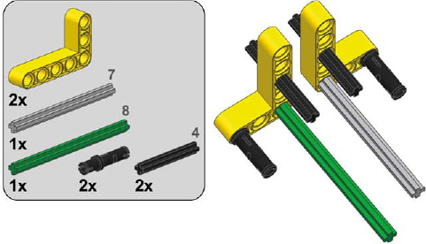
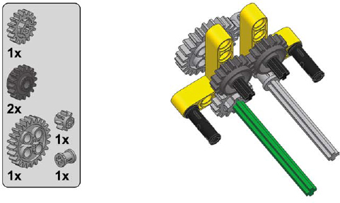
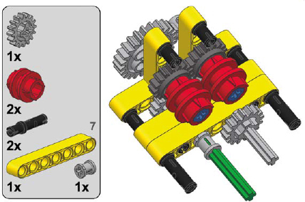
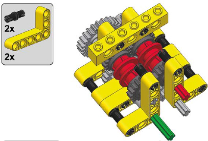
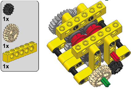
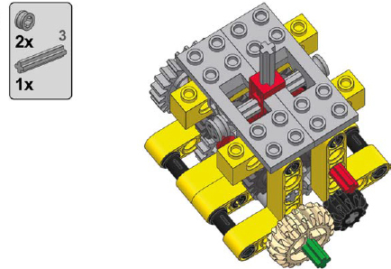
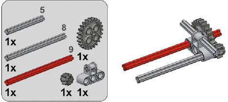
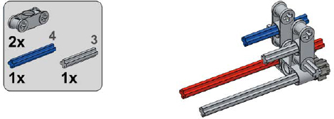
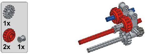
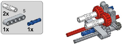
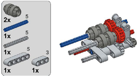
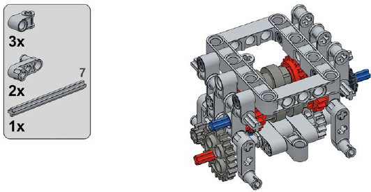
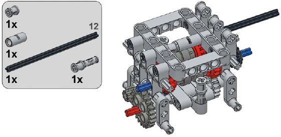
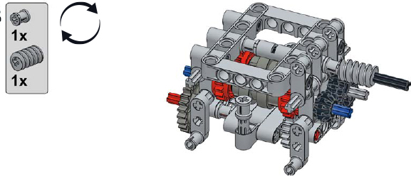
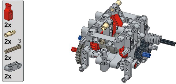
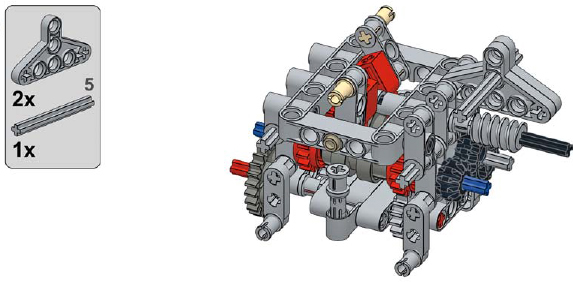
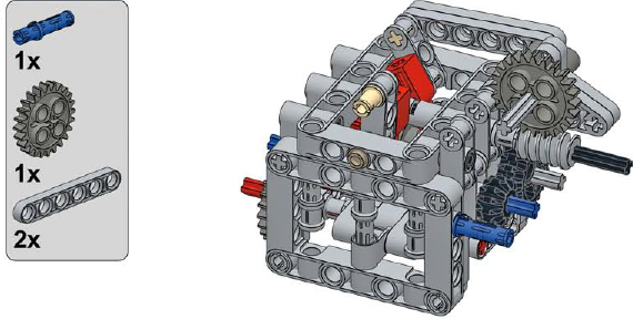
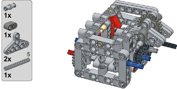
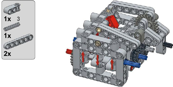
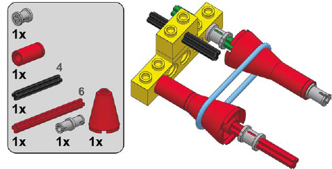
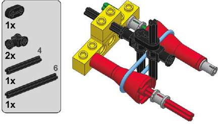
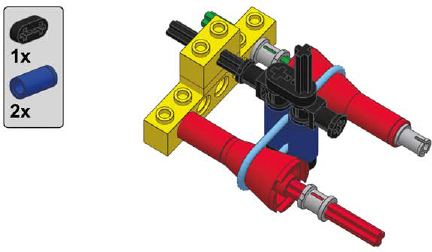
a 2-speed synchronized transmission
1
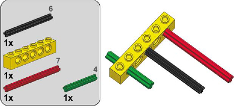
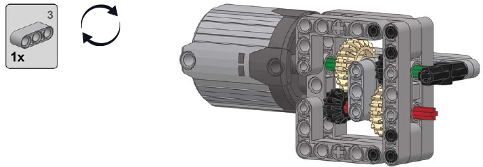
2
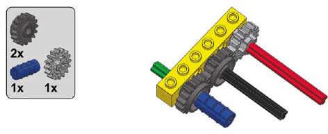
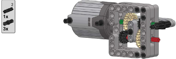
3

4
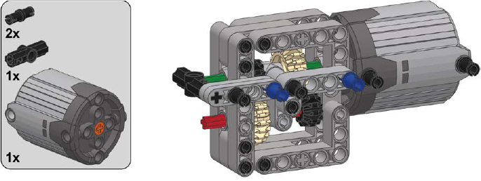
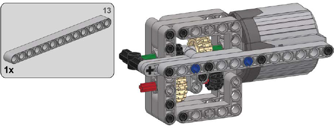
a 2-speed linear heavy-duty transmission
1
2
3
4

5
6

7
8
9
10
11
12
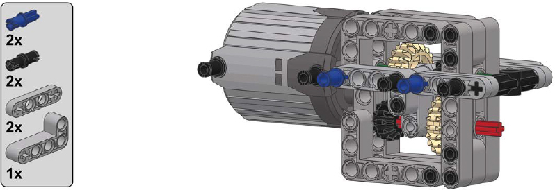
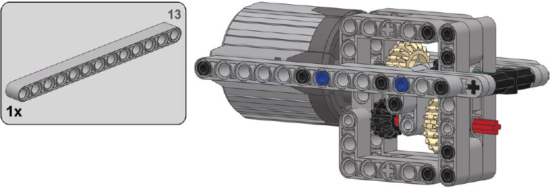
13
a 2-speed RC motor transmission
1
2

3

4

5

a 2-speed orbital transmission
1
2
3
4

5

6
7
8
a 2-speed ratchet transmission
1
2
3
4
a 3-speed linear transmission
1

2
3

4
5
6
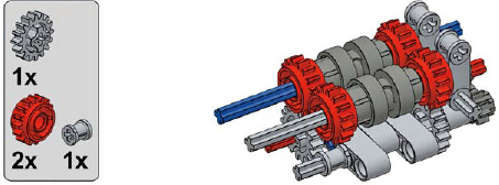
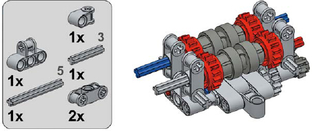
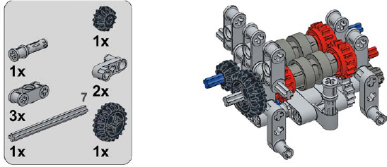
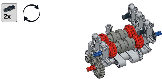
a 4-speed synchronized transmission
1
2
3

4
5

6
7
8

9
a 4-speed sequential RC synchronized transmission
1
2
3
4
5
6
7
8
9
10

11
12
13
14
15
16

17
18
19
20
21

22
a 10-speed synchronized transmission
1

2
3

4
5

6

7
8

9
10
11

12

a continuously variable transmission
1
2

3
4
5
6
