14
LEGO Power Functions system
The LEGO Power Functions system (or PF for short), introduced in 2007, is a combination of LEGO elements that allows you to motorize your constructions, equip them with lights, move them with linear actuators, and, above all, control them remotely. In this chapter, we will learn how this system works and how its elements can be combined.
The core parts of the Power Functions system can be divided into three groups: power supplies, control elements, and motors. There are several types of motors in the Power Functions system, and all of them are described in Chapter 13. The Power Functions system allows us to control motors with more flexibility, offering fine-grained control of speed and the ability to control multiple elements at once.
NOTE One of the novelties of the Power Functions system is that the majority of its elements have been released as stand-alone, separate LEGO sets. A list of these sets can be found at the end of this chapter.
manually controlling motors
To control a motor by hand with the Power Functions system, you need only two elements: a power supply and a motor, as shown in Figure 14-1. All Power Functions power supplies come with controls on them, some basic and some advanced, and these controls affect any and all motors directly connected to the power supply.
Note that the plugs of the Power Functions wires are stackable, and we can connect many wires to a single outlet, as shown in Figure 14-2.
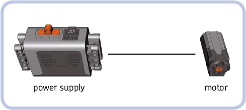
Figure 14-1: The simplest power Functions motor configuration
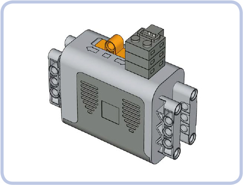
Figure 14-2: A regular power Functions battery box with three plugs stacked on its outlet. Three elements can now be powered and controlled from this box at the same time.
The simple power supply and motor configuration has one serious disadvantage: If many motors are connected to one power supply, they will all work as one. This is inevitable when using the power supply as a control mechanism, which is why the Power Functions system includes a separate group of control elements. The simplest element from this group is a switch, shown in Figure 14-3.
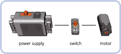
Figure 14-3: A slightly more complicated configuration for the power Functions system
Just like all control elements, the switch is connected between the power supply and the element we want to control. It has three positions—forward, stop, and reverse—and they affect all elements connected to the switch.
Note that in this configuration, the controls of a switch and the regular battery box can work at the same time, so either can be used to control the motor. (But if the power supply is set to off, obviously, the setting of the switch won’t affect the motor.)
remotely controlling motors
While direct manual control is a nice option, the key advantage of the Power Functions system is the ability to control motors remotely. This is done by a pair of elements: a remote and a receiver (see Figure 13-2 on page 184).
You can think of the remote and receiver as a switch split into two parts. One part, the receiver, is between the power supply and the elements we want to control, just like a switch. It also has a wire just as a switch does. The other part, the remote, has no wires and isn’t physically connected to anything. It sends commands to the receiver using an invisible infrared link, just as most TV remotes do. It also houses batteries, just as TV remotes do, so it needs no external power supply. Your construction, with the receiver integrated into it, can be controlled from a distance using the remote.
It’s important to remember that the infrared link between remote and receiver has its limitations. The black, semitransparent parts of both remote and receiver house infrared sensors that need to be exposed and within a line of sight of each other to maintain a link. The remote is actually sending out invisible light signals, and they won’t reach the receiver if something blocks their way or if they are sent in the wrong direction. They can, however, bounce off walls and ceilings; so as long as you remain indoors, pointing the remote in the receiver’s general direction is sufficient. You can also cover up the receiver almost entirely in constructions intended for indoor use, as Figure 14-4 shows. A 2×2 opening around or slightly above the receiver’s top will do the job. Outdoors, maintaining the link between remote and receiver is more difficult: The remote has to be aimed with good precision, and its range can drop to as little as 1 m if the receiver’s sensor is exposed to strong sunlight.

Figure 14-4: An ir receiver doesn’t have to make your construction ugly. You can cover it up almost completely, leaving only the 2×2 opening around the sensor. The cover can end up level with the sensor or even slightly above it and still work, as long as you hold the remote higher than the receiver.
As Figure 14-5 shows, a receiver has two levers, one blue and one red, along with two outlets colored the same way. The levers and outlets correspond—the blue lever controls everything connected to the blue outlet, while the red lever controls everything connected to the red outlet. The remote comes with two pole reversers, one for each outlet/lever. The reversers’ function is simple: They determine whether pushing a lever forward makes a motor connected to the corresponding outlet rotate forward or in reverse. The blue/red elements are independent and can work at the same time. In other words, the blue lever doesn’t interfere with the red lever, and the blue pole reverser doesn’t interfere with the red pole reverser.
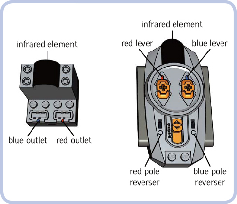
Figure 14-5: The receiver and basic remote

Figure 14-6: The channel selectors on a receiver and basic remote
There is a reason why we said that a lever controls everything connected to its corresponding outlet. Since the Power Functions plugs are stackable, you can connect as many motors or other elements to an outlet as you want—all of them will be controlled simultaneously by the corresponding lever. This means that you can control more than two motors using a single receiver, and the motors connected to the same outlet will work as one. For example, you can drive your vehicle with two motors together when one is too weak, or you can have the headlights in your vehicle turn on as it drives.
NOTE The actual number of elements that can run off a single power supply simultaneously is limited by their total power consumption. If it becomes too high, the power supply shuts down. This is most likely to happen with motors and least likely to happen with LEDs.
This limits us to controlling two functions independently per one individual receiver. We can, however, control more functions using many receivers and just a single remote. As Figure 14-6 shows, both receiver and remote come with a simple orange switch called a channel selector. It has four positions numbered from 1 to 4. With a channel selector, we can use a single remote with up to four receivers.
Imagine that we have four receivers, each set to a different channel: the first receiver set to channel 1, the second to channel 2, and so on. If you set the channel selector on the remote to 1, only the first receiver will react to the remote and the other three will not. Similarly, if you set the remote’s selector to 2, only the second receiver will react to it; if you set it to 3, only the third one will react; and if you set it to 4, only the fourth one will react. This way you can control up to eight functions independently with a single remote, but since the remote can only be set to one channel at a time, you can control only two functions at the same time. Controlling another two functions requires switching the remote’s channel selector to a different position. Figure 14-7 shows the 1 remote / 4 receivers / 8 motors arrangement.
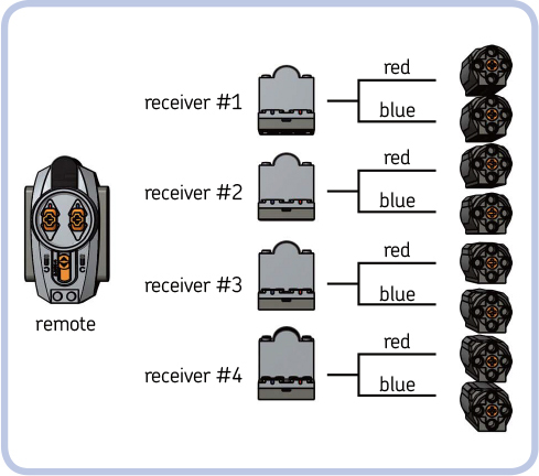
Figure 14-7: Each receiver is set to a different channel and has one motor connected to each of its outlets. In this way, eight motors can be controlled independently.
Controlling just two functions simultaneously is clearly a limitation—but one that can be overcome with additional remotes. You can use many remotes at the same time, even four, each tuned to a different channel. Many builders prefer to use several remotes at once rather than a single remote that needs switching between channels. It’s even possible to use many remotes set on the same channel with a single receiver, for example, to let several people control the same construction.
Note that when many remotes are sending commands at various channels at the same time, receivers react more slowly. This is because each receiver reads commands from all four channels all the time, and its channel selector tells it only which to ignore and which to accept. When there are many commands to read simultaneously, the receiver is slowed down.
Now that we know how the Power Functions system works, let’s take a look at its individual elements.
power supplies
The power supplies of the Power Functions system come in several variants, allowing us to choose between two types of batteries or even freeing us from the need for regular batteries at all. Every power supply can have many elements connected to it, but if too many elements are running off a single supply simultaneously, the electronic countermeasures in it will shut it down. This is most likely to happen with power-costly elements, such as motors. When it does, simply turn the supply off and on again.
AA battery box
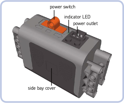
This simple box contains six AA batteries, with two side bays for three batteries each. The box is 11×4×7 studs, with an orange power switch protruding by 1 stud on top of it. The switch has three positions—forward, stop, and backward— and the indicator LED adjacent to the switch shines green on the first and last position. The box is completely studless and connects by pin holes on its sides.
AAA battery box
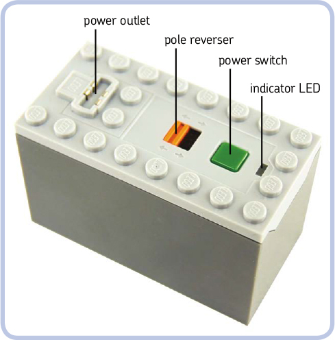
The box contains six AAA batteries, which are inserted by unscrewing the box’s bottom. The box is 8×4×5 studs, with a studfull bottom and top. Its power switch has the form of a simple green button. Pushing the button toggles the box between on and off. The box also has an indicator LED that shines green when the box is on and a simple orange pole reverser that determines whether turning the box on makes motors connected to it run forward or backward. The AAA batteries are smaller and lighter than AA ones; they can’t power as many elements simultaneously, and they last roughly a third as long.
NOTE This box comes with a timer: Once turned on, it will turn itself off after 2 hours. You can stop the timer by holding the power switch down for 3 seconds. Turning the box off and on again resets the timer. This feature, intended to prevent the batteries from running dry if you forget to turn the box off, can be mistaken for a malfunction or battery failure.
rechargeable battery
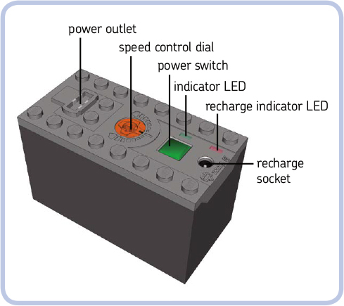
This self-contained battery with rechargeable power cells can be recharged using a transformer, without the need for replaceable batteries of any type. It’s 8×4×5 studs, with a studfull bottom and top. Unlike regular battery boxes, it does not open. Its power switch has the form of a simple green button, and pushing it toggles the battery between on and off. Next to the power switch, there is an indicator LED that shines green when the battery is on and an orange speed dial with 15 positions: 7 forward, 7 backward, and 1 stop position. Turning the dial controls the speed of all motors and the brightness of all lights connected to the battery. It does not affect receivers connected to it. On the other side of the power switch, there is a recharge socket for the transformer, and an adjacent indicator LED blinks red during recharging and shines red when recharging is complete.
The battery houses two lithium ion polymer cells with a total capacity of 1100 mAh, providing a constant voltage of 7.4 V. The LEGO Group recommends recharging it with a dedicated transformer, sold separately, and defines the full recharge time as 4 hours.
While costly, the battery can be attractive to builders who use plenty of standard batteries. It allows them to build lighter and simpler because it weighs under 80 g (the AA battery box can weigh over 200 g, depending on the batteries’ make). This battery can also be integrated into your construction permanently, with only a 2×2-stud opening to access its power switch and recharge socket. It provides lower voltage than standard batteries do (9 V) but higher voltage than rechargeable AA batteries do (7.2 V). Its capacity is smaller than that of most AA batteries, meaning that it runs dry more quickly, but it makes up for this by never needing a battery replacement. When empty, it can be recharged inside your construction by simply connecting the transformer to it, while the battery boxes usually need to be taken out of your construction to replace batteries.
NOTE This battery also comes with a timer: Once turned on, it will turn itself off after 2 hours. Unlike the timer in the aaa battery box, this timer can’t be stopped. Turning the battery off and on again resets the timer.
receiver
The Power Functions receiver, shown in Figure 14-8, is 4×4×5 studs and requires at least a half stud of space at the back for plugs connected to it. It has a studfull bottom and top and two pin holes in front. It also has a four-position channel selector in front and an indicator LED adjacent to it, which shines green when the receiver is under power and blinks when the receiver accepts commands from its selected channel.
In 2012, a version with upgraded electronic components was released. This version is distinguished by the V2 printed on the front (see Figure 14-9) and is otherwise identical externally. It delivers more power to the motors, meaning that it can fully power two PF L motors through a single outlet. You can connect two L motors to a single outlet of the older version, too—they just won’t run at full power. Note that using a V2 receiver with PF M motors is not recommended.
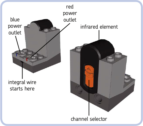
Figure 14-8: A front and back view of the power Functions receiver

Figure 14-9: The V2 power Functions receiver. Note the shining indicator led.
remotes
As shown in Figure 14-10, there are two types of Power Functions remotes: a basic remote and a less common speed control remote. They work in a slightly different ways:
basic remote The go command makes motors run until the go command is no longer received.
speed control remote The go command makes motors run until the stop command is received.
The key difference is that when the basic remote stops sending the go command, the motors stop. This means that we must maintain an infrared link between remote and receiver as long as we want the motors to go. Note that while moving the remote’s lever to the stop position stops motors immediately, breaking the infrared link means losing control over the motors. With the link broken, they carry on the last received command for 2 seconds and then stop—unless we manage to reestablish the link during these 2 seconds.
With a speed control remote, we just have to send the go command to start motors and the stop command to stop them. There is no need to maintain a constant infrared link between sending these two commands.
Another difference is how the remotes send commands. The basic remote keeps sending a command continuously for as long as you keep its lever in forward or reverse position. The speed control remote sends a command just once for every turn of a dial and once for pressing the stop button.
NOTE It’s not recommended to use both types of remotes with the same receiver simultaneously. They will interfere with each other, causing all motors connected to the receiver to stop or to behave erratically.
This limitation becomes complicated when we want to drive and steer a model with a speed control remote, which is well suited for controlling drive but ill suited for controlling steering (unless you’re using the Power Functions Servo motor, as explained in “The Speed Control Feature” on page 199). The best solution, then, is to control steering with the basic remote on another channel by connecting the steering and driving motors to two separate receivers set to two different channels. The steering can be controlled by one receiver set to channel 1, and the drive can be controlled by a second receiver set to channel 2. There will be no interference as long as the remotes are set on proper channels.

Figure 14-10: The power Functions remotes: basic (left) and speed control (right). Each is powered by three aaa batteries.
basic remote
The basic remote comes with two levers: red and blue, each with forward, stop, and reverse positions. The levers return to the stop position when released. The basic remote also has two pole reversers, one for each lever. The remote is 10×6×4 studs and has a channel selector and an indicator LED that shines green for as long as a command is being sent. The remote is powered by three AAA batteries inserted by unscrewing a cover on its bottom. Both its sides have seven pin holes each, allowing you to connect several remotes side to side with pins.
speed control remote
The speed control remote comes with two dials: red and blue. The dials have no definite positions and stay in place when released. This remote, too, has two pole reversers (one for each dial), two red stop buttons (one for each dial), a channel selector, and an indicator LED that blinks green when a command is sent. The remote is 10×12×4 studs and powered by three AAA batteries inserted by unscrewing a cover on its bottom. Both its sides have seven pin holes each, allowing you to connect several remotes side to side with pins.
Note that this remote works in a special way with the Power Functions Servo motor: Instead of controlling the motor’s speed, the speed control remote controls the angle of its output. So rotating the dial 30 degrees right makes the Servo motor’s output rotate 30 degrees right, too—or left, depending on how you set the remote’s pole reverser.
the speed control feature
There are 15 possible speeds in the Power Functions system: 7 forward, 7 reverse, and 1 “zero” speed, which stops the motors. Speed control is carried out by changing the voltage, meaning that speed control can affect not only a motor’s speed but also the brightness of the lights.
The basic Power Functions remote uses only three speeds: top speed forward, zero speed, and top speed reverse. The speed control Power Functions remote, on the other hand, comes with dials that can be rotated in one direction or another. Rotating a dial in one direction sends a speed +1 command; rotating it in another sends a speed -1 command, but the rotation has to stop for a moment for the remote to finish sending the command. This means that the dials’ rotation is intermittent, not continuous.
The following Power Functions elements have been released as separate LEGO sets:
![]() 8869: switch
8869: switch
![]() 8870: LED lights
8870: LED lights
![]() 8871: extension wire, long
8871: extension wire, long
![]() 8878: rechargeable battery
8878: rechargeable battery
![]() 8879: speed control remote
8879: speed control remote
![]() 8881: AA battery box
8881: AA battery box
![]() 8882: XL motor
8882: XL motor
![]() 8883: Medium motor
8883: Medium motor
![]() 8884: receiver
8884: receiver
![]() 8885: basic remote
8885: basic remote
![]() 8886: extension wire, short
8886: extension wire, short
![]() 8887: rechargeable battery transformer
8887: rechargeable battery transformer
![]() 88000: AAA battery box
88000: AAA battery box
You can rotate a dial through all speeds, from +7 to –7, but note that dials don’t stop even when maximum speed is reached. Since dials have no definite positions and can rotate infinitely, sending one command after another, it’s impossible to change speed very quickly or to tell the current speed from the dials’ position. This is why the speed control remote comes with separate stop buttons, one for each dial. While it’s possible to rotate a dial to stop a vehicle, it takes some time and precision; you have to watch the vehicle itself to know when you’re changing the speed to zero, for example, and not to -1. The stop buttons are the quick and sure way to go—you’ll see why when your model is heading fast toward the edge of a cliff!
Note that the rechargeable Power Functions battery has a dial that does have definite speed positions. This control affects all motors and lights connected to the battery directly or through a switch but not through a receiver, as the receiver ignores the battery’s dial.
modifying the remotes
Many possible modifications can make the remotes better suited for our needs. Let’s look at three of them.
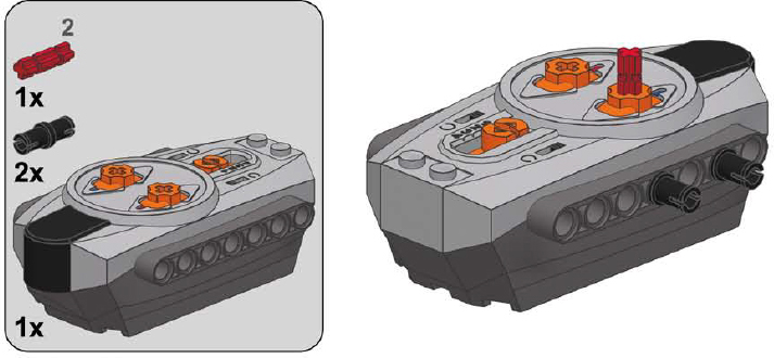
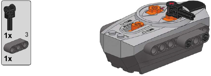
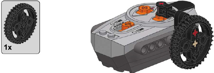
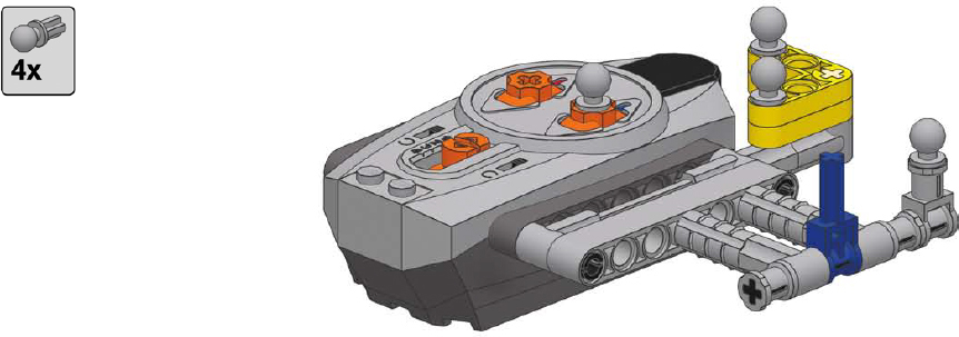
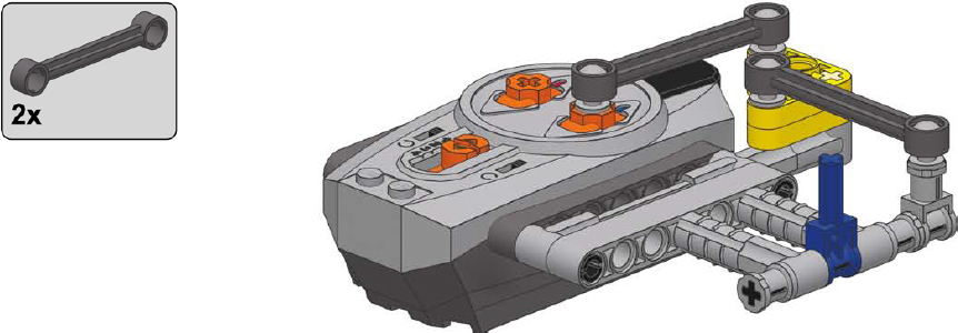
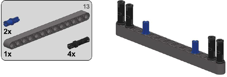
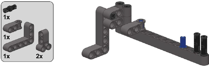
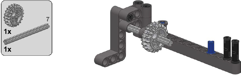
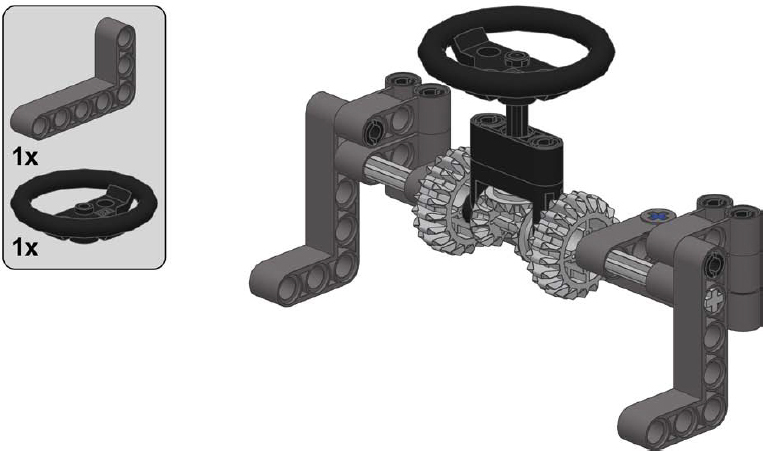
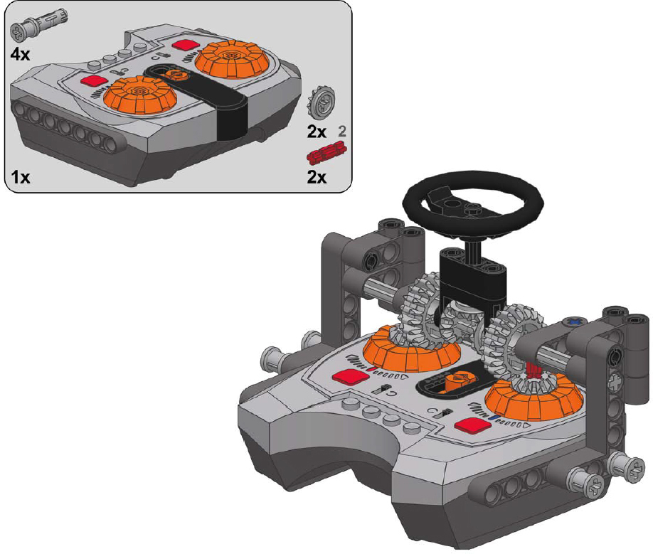
a basic remote with steering wheel
This simple, robust modification is suitable for driving and steering.
1
2
3
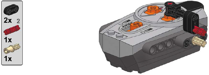
4
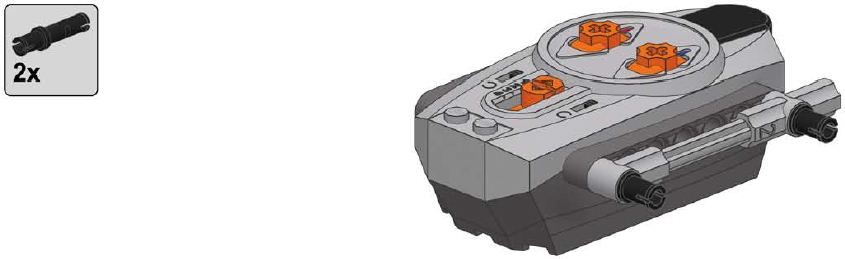
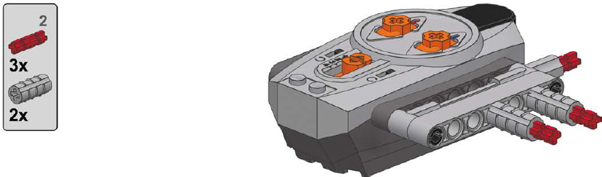
a basic remote with sideways lever
This more complex and less robust modification uses links.
1

2
3

4
5

6

7
8
a speed control remote with central steering wheel
This modification is designed to control tracked vehicles, with each speed dial controlling a single track. Two speed dials are connected by a central steering wheel, which can be rotated as well as tilted forward and backward. With properly switched pole reversers, the steering wheel tilt controls drive, and the steering wheel rotation controls steering. To make the vehicle drive forward and then turn right, for instance, you would tilt the steering wheel forward and then rotate it right.
Note that this modification is subject to the disadvantages of the speed control remote—that is, it is limited to sending no more than two commands per second. It works best when operated carefully and not too fast.
1
2
3
4

5

6

7
8
linear actuators
Linear actuators, designed as supplementary parts of the Power Functions system, are an interesting alternative to the LEGO pneumatics. They come in two variants, large and small, and both work thanks to inner screws. Each actuator has an input whose rotation makes the actuator extend or retract, depending on direction. When an actuator is extended or retracted to maximum, its inner clutch engages, allowing the input to continue rotating without damaging the actuator.
The actuators can thus be motorized without external clutches, and their inner gear ratio makes them work well with Power Functions motors without the need for external gearing. Their performance differs from that of LEGO pneumatics, so they can replace LEGO pneumatics in some applications and complement them in others. Let’s have a look at linear actuators and then compare them to pneumatics.
large linear actuator

A large linear actuator is 11 studs long when fully retracted and 16 studs long when fully extended. It has a diameter of 2 studs, and it comes with two types of brackets (shown in Figure 14-11) that increase the diameter to 3 studs. One bracket provides an articulated mounting for the actuator, and the other provides a fixed one. It takes one or two 2L axles to firmly attach a bracket to the actuator. Examples of driving an actuator are shown in Figures 14-12 and 14-13.
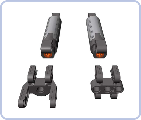
Figure 14-11: A large linear actuator plus bracket with articulated (left) and fixed (right) mounting
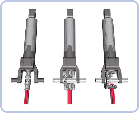
Figure 14-12: Three examples of transferring drive to the small linear actuator. Note that all three have a 1:1 gear ratio.

Figure 14-13: The bracket with fixed mounting can connect a motor and actuator as a single unit that can pivot around one of the mounting axles (light grey).
In 2010, LEGO announced that the actuators released earlier had a design flaw that could result in high friction occurring inside them when under load and lead to slow and coarse operation. A new design was introduced in September 2010. Actuators produced after this date are externally identical to the older ones, so the easiest way to distinguish them is by checking the production code on each actuator, shown in Figures 14-14 and 14-15.

Figure 14-14: The location of the production code on the actuator is shown by the red arrow. Look for three digits and the letter X minted on the flat dark grey surface.
The production code consists of three digits and the letter X—for example, 36X0. The first two digits mark the week of the actuator’s year of production, and the last digit is the ending digit of the year of production. So the 36X0 production code means the 36th week of 2010; this is exactly when the new design was introduced. Actuators produced before this date—for example, 29X0—are of earlier design; actuators produced after this date—for example, 40X0—are of improved design. Keep in mind that even if you have “flawed” actuators, it doesn’t necessarily mean that failure will occur.
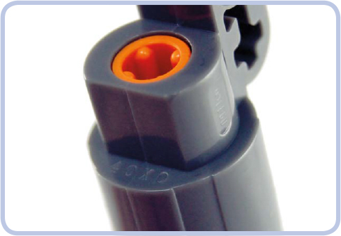
Figure 14-15: A close-up view of a linear actuator. The production code is 40X0, which means the 40th week of 2010, or 4 weeks after the improved design was introduced.
The large linear actuators can handle impressive loads. Their disadvantage, however, is their inner clutch, which creates significant noise and vibration when engaged.
small linear actuator
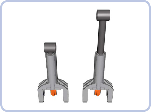
A small linear actuator is 7 studs long when fully retracted and 10 studs long when fully extended. It has a diameter of a single stud and a fixed bracket that is 3 studs wide. Instead of an axle hole, it has input in the form of a 1L axle. Figure 14-16 shows simple ways of driving a small linear actuator.

Figure 14-16: Three examples of transferring drive to the small linear actuator. Note that all three have a 1:1 gear ratio.
The load capacity of the small linear actuator is much smaller than that of its larger variant but still impressively useful given its size. Unlike the large actuator, the small one comes with a plastic internal shaft, which is less robust than the large actuator’s metal one. The clutch in the small linear actuator works very smoothly and engages almost seamlessly. The small actuator can be very space efficient when combined with the Medium motor.
linear actuators vs. pneumatics
Linear actuators can do most of the tasks that pneumatic cylinders can, but they were not designed to replace them. The two systems differ in many areas, and the best results can be achieved by combining them so that they complement each other’s advantages. Linear actuators have the following advantages when compared to pneumatics:
![]() Have a higher load capacity
Have a higher load capacity
![]() Can be motorized directly, without the need for compressors or valves
Can be motorized directly, without the need for compressors or valves
![]() Maintain better accuracy in all positions, as they don’t depend on air pressure
Maintain better accuracy in all positions, as they don’t depend on air pressure
![]() Maintain their position under any load; their inner screws lock them once stopped so they can’t be moved by the weight of the load
Maintain their position under any load; their inner screws lock them once stopped so they can’t be moved by the weight of the load
![]() Don’t have pneumatic hoses, just driveshafts
Don’t have pneumatic hoses, just driveshafts
But they also have the following disadvantages:
![]() Can be difficult to transfer drive to, as driveshafts are less versatile than pneumatic hoses; this disadvantage grows with more complex systems and with the number of actuators
Can be difficult to transfer drive to, as driveshafts are less versatile than pneumatic hoses; this disadvantage grows with more complex systems and with the number of actuators
![]() Move with constant speed, lacking the smoothness of movement that can be achieved with pressure-dependent pneumatics
Move with constant speed, lacking the smoothness of movement that can be achieved with pressure-dependent pneumatics
![]() Are generally larger in size
Are generally larger in size
![]() Large actuators can cause problems when their inner clutches engage, as they produce lots of vibrations
Large actuators can cause problems when their inner clutches engage, as they produce lots of vibrations
![]() Are much more difficult to pair
Are much more difficult to pair
![]() Resemble real-life hydraulic systems significantly less than pneumatics do
Resemble real-life hydraulic systems significantly less than pneumatics do
extension wires
We already know that the vast majority of the Power Functions electric components come with integral wires that are permanently attached to them on one end and have a plug on the other. These wires are obviously limited in length, which is why two kinds of extension wires were introduced: a 20 cm wire and a 50 cm wire (see Figure 14-17).
Beyond the obvious goal of adding extra length to any PF electrical connection, the extension wires have one very important feature: Each comes with one adapter plug. An adapter plug is a special variant of the Power Functions plug that can have regular PF plugs attached on top of it and old 9V system plugs attached to the bottom of it (see Figures 14-18 and 14-19). This way, each extension wire allows you to connect elements of the Power Functions and old 9V systems together.
A variety of 9V elements can be controlled with the Power Functions system, including all motors (the speed control feature works with them as well) and all types of lights. It is also possible to integrate PF elements into the 9V system to a limited degree. For example, the PF motors can be controlled with 9V battery boxes and switches, but PF receivers work only with PF power supplies.

Figure 14-17: Power Functions extension wires: 50 cm long (top) and 20 cm long (bottom)
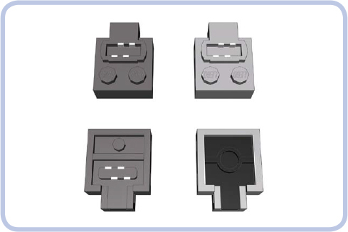
Figure 14-18: Top and bottom view of a regular Power Functions plug (left) and the adapter plug (right). Each extension wire comes with one plug of each type.
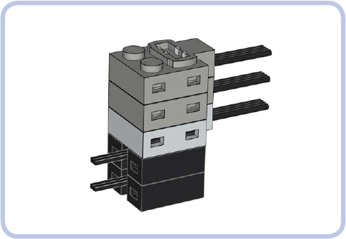
Figure 14-19: The Power Functions adapter plug (light grey) can have an unlimited number of Power Functions plugs (dark grey) attached on top of it and an unlimited number of 9V plugs (black) attached to its bottom.
miscellaneous elements
There are just a few more elements of the Power Functions system, and most of them are highly specialized—for example, train sets—so we will omit them here. That leaves just two elements so universal that they deserve to be described.
switch
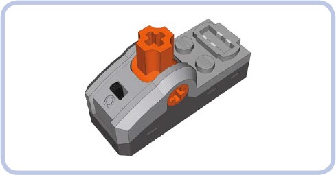
As mentioned earlier, the switch is the simplest control element. It is 5×2 studs and has a 1-brick-tall base, and it comes with an integral wire, one power outlet, one pole reverser, and an orange lever. The lever is identical to the one on the basic remote, with three positions—forward, stop, and backward—except that it doesn’t return to the central position. It also has an axle hole through which any axle can be put—this comes in handy, for example, when we want to motorize the switch.
LED lights
The PF system’s lights, shown in Figures 14-20 to 14-22, are a pair of LEDs with a piece of wire and a regular Power Functions plug. At half of its length, the wire enters a black 2×2×1 brick that separates in two, so the two LEDs can be placed relatively far from each other. Note that the black brick is not a plug of any kind: It’s fully closed, just like a standard LEGO brick. The LEDs are enclosed in transparent housings that are less than 2 studs tall and less than 1 stud wide and that have protruding tubes with LEDs inside that fit perfectly into a pin hole.
The LEDs provide bright white light, directed only forward. Their power consumption is minimal, and their brightness can be controlled with the Power Functions speed control feature. Note that the type of LEDs used by LEGO has changed over time: The glow of older batches is slightly yellowish, while the glow of newer batches is bluish.

Figure 14-20: The Power Functions LEDs with a hamster provided for scale
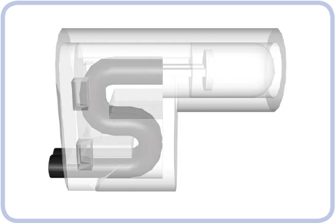
Figure 14-21: Side view of the LEGO LED. You can see part of the wire tucked in to prevent it from being ripped off. The actual LED is located in a protruding tube that fits into a pin hole and is slightly less than a single stud long.
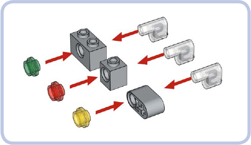
Figure 14-22: The most common examples of installing LEDs in other LEGO pieces. The LEDs fit perfectly into a pin hole. Since their protruding part is less than a stud long, there is still enough room to put in, for example, semitrans-parent round plates from the other side, creating lights in various colors.