16
wheeled steering systems
The steering of wheeled vehicles is a complex subject in automobile design. While some real-life issues are of lesser importance in LEGO models because of their limited size and weight, it still pays to understand the principles at play.
In this chapter, we’re going to learn how to build typical LEGO steering systems as well as how to implement optional features, such as return-to-center steering. We’ll also explore issues of steering geometry and multi-axle steering.
Note that this chapter omits vehicles with fewer than four wheels. Steering bikes or trikes is elementary, so we are moving straight to where the real challenges begin.
basic LEGO steering systems
The steering systems in LEGO constructions can be built with a number of specialized pieces, but it’s also perfectly possible to rely only on common pieces. Let’s start our exploration of steering by examining a typical steering mechanism, shown in Figure 16-1.
Note that we will be using colors consistently throughout this chapter: The black pieces are parts of the chassis, and the yellow one is obviously a steering wheel. That leaves four other important parts:
a steering shaft (red) This is an axle that connects a steering wheel or a motor to the pinion of the rack-and-pinion gearset.
a rack-and-pinion gearset (grey) This gearset consists of a pinion (here, an 8-tooth gear) and a rack, which is a toothed plate, below it (see Figure 16-4); when the pinion rotates left or right, it makes the rack slide.
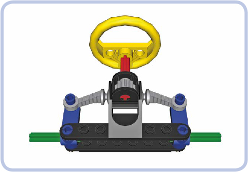
Figure 16-1: A typical LEGO steering mechanism
steering arms (blue) These arms rotate around the connection to the chassis, and their rotation is controlled by the rack.
spindles (green) These are the axles in the steering arms on which the wheels are mounted.
Figure 16-2 shows our mechanism in action. Rotating the steering arms makes the entire vehicle turn. And obviously, to turn, the vehicle needs at least one more axle, as Figure 16-3 shows.
In Figure 16-2, the rack gear is a specialized piece (#2791) that is slightly elastic, allowing it to bend to stay mated with the round pinion gear as the steering wheel turns. The pinion gear can be used with other gears, but we’d have to compensate for the rotation of the steering arms. Figure 16-4 illustrates the problem.
When the steering arms are turned, the pins that connect them to the rack actually trace part of a circle. This causes the rack to move in two dimensions: not only left and right but also forward and backward. Only the lateral movement is desired, as the forward-and-backward displacement can disengage the rack from the pinion. Figure 16-5 shows the simplest solution to the problem: adding an extra pinion.
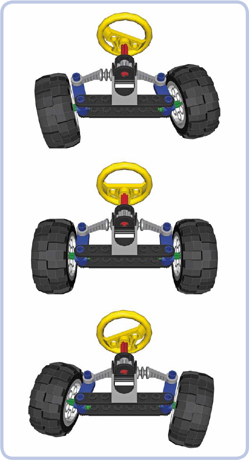
Figure 16-2: Our simple steering mechanism in extreme left, straight, and extreme right positions

Figure 16-3: A LEGO vehicle with two axles: one fixed and one steered
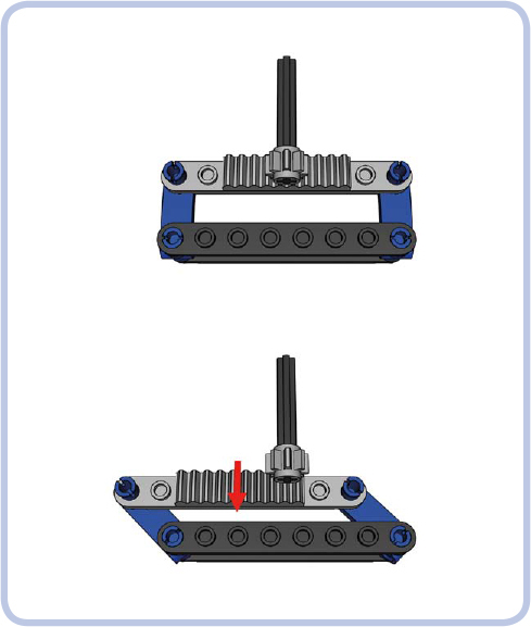
Figure 16-4: The rotation of the steering arms (blue) makes the rack (light grey) move not only side to side but also forward and backward.
Another solution is to place the pinion in the middle of the rack’s path of forward-and-backward motion, as shown in Figures 16-6 and 16-7.
These figures also introduce a new, simple element of the steering system. When we use nonspecialized pieces to build a steering system, we’ll use two pieces: a rack gear (shown in light grey under the pinion), which is a 1×4-stud plate with teeth on top of it, and a tie rod (shown in light blue). A tie rod connects the ends of the steering arms to the rack gear.
As you can see, the tie rod travels forward and backward, requiring a margin of free space—the 2-stud-wide gap around it. But we may not want to waste space for such a gap; another solution is to make the rod more complex, as shown in Figure 16-8.
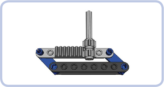
Figure 16-5: The simplest solution to an “escaping” rack is using two pinions so that when the rack moves away from one, it will be meshed with the other.
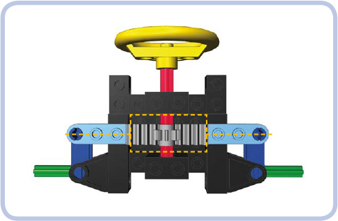
Figure 16-6: A steering mechanism in straight position. Note that the light blue tie rod is located in the center of the 2-stud-wide gap around the pinion.
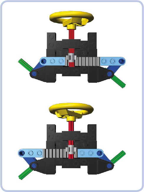
Figure 16-7: A steering mechanism in extreme right and extreme left positions. Note that the tie rod moves forward inside the 2-stud-wide gap around the pinion.
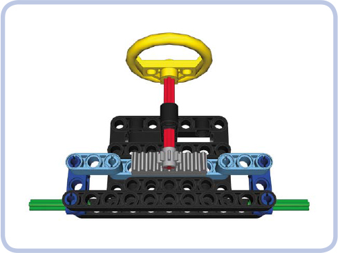
Figure 16-8: A steering mechanism with a three-piece tie rod. The short, articulated sections on the sides pivot to accommodate the rotation of the steering arms.
Here the tie rod consists of three sections: a long central one (with the rack) and two short ones on its sides, connected by pins. These short sections pivot to accommodate the rotation of the steering arms and reduce the central section’s forward-and-backward travel to zero, as Figure 16-9 shows.
The three-piece tie rod is a reliable and popular solution, but its side sections must be shorter than the central one. The whole assembly is rather wide and thus not suited for narrow vehicles. We can solve this by building a very simple steering system in which the rack gear is replaced by a lever, as Figure 16-10 shows.
You now know three solutions to the problem of a tie rod’s travel, and you have seen examples of simple steering systems built with a handful of common pieces. Now that your steering system is working, you may want to add features to it.

Figure 16-9: A steering mechanism with a three-piece tie rod in extreme left and right positions. Note that the longitudinal travel of the central section is zero.
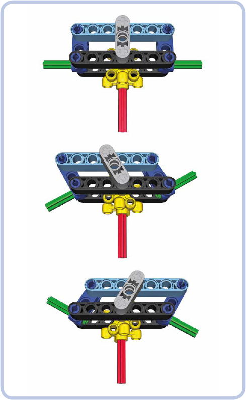
Figure 16-10: A steering mechanism without a rack. Instead, it uses two knob wheels and a short lever (grey) to transfer movement from the steering shaft to the tie rod.
return-to-center steering
Return-to-center steering is just what the name implies: a mechanism that returns the steering system to the center (straight) position when the system is released. Such a mechanism is best placed between the steering system and a motor controlling it, and such a “self-centering” design complements the use of remote controls. It allows you to build a steering system that steers to extreme left or extreme right when you push levers on your remote and that returns to center when you release it.
NOTE These mechanisms use the basic Power Functions remote and a regular motor. You can use the speed control PF remote and PF Servo motor instead, which together provide not only a return-to-center system but also proportional steering. See Chapter 13 for details.
The easiest way to build a self-centering steering system with LEGO pieces is to use a rare specialized piece, #x928cx1, often called a hockey spring. It comes with a spring inside and can be attached to a PF Medium motor (as shown in Figure 16-11). In such a configuration, it will backdrive the motor to the central position every time the motor stops.
If you cannot find this specialized piece, you can use a rubber band as a simple centering mechanism. Shown in Figure 16-12, the mechanism consists of the band (white), which squeezes two beams (yellow) together to the sides of a connector sitting on the steering shaft (red). As the motor starts to rotate the shaft, the connector pushes the beams apart. If the rubber band is strained enough, it will stop the connector quickly, and when the motor stops, it will squeeze the beams back together, returning the connector and the shaft to the central position. Note that you have to find a rubber band providing just the right tension for this mechanism to operate smoothly.
As with any mechanism, return-to-center steering has its pros and cons. It works fast and simplifies the control of a model, but it doesn’t allow accurate maneuvering because it only has three possible positions. This makes it better suited for fast models where a steering system has to react quickly, rather than for slower ones that benefit from a steering system that allows for greater accuracy. It’s also risky to use return-to-center steering with a large steering lock because rapid wide turns can make a vehicle unstable. (Steering lock is the maximum angle that wheels on a steered axle can be turned, as described in Chapter 1.) In my experience, any model that isn’t built specifically for speeding will be better off with a regular steering system that allows you to adjust the driving direction accurately. In most cases, the PF Medium motor geared down to a 9:1 gear ratio provides optimum speed/accuracy balance for a regular steering system.
Ackermann steering geometry
When a wheeled vehicle makes a turn, its inner and outer wheels follow circles of different radii because the width of the vehicle separates them. If the inner wheels follow a circle of radius r1, then the outer wheels follow a circle of radius r2 (equal to r1 plus the width of the vehicle), as Figure 16-13 shows.
A regular steered axle turns both left and right wheels at exactly the same angle, which means that none of the wheels follows exactly its proper radius. This creates additional friction and tire wear. Ackermann steering geometry corrects that by turning wheels at different angles. More specifically, it turns them so that they are perpendicular to the center of the vehicle’s turning radius, as shown in Figure 16-14.
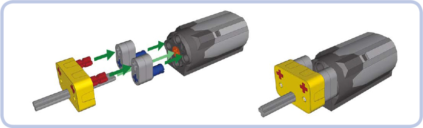
Figure 16-11: The hockey spring (yellow) and a schematic for attaching it to a PF Medium motor

Figure 16-12: The rubber band–based return-to-center steering attachment for a PF Medium motor
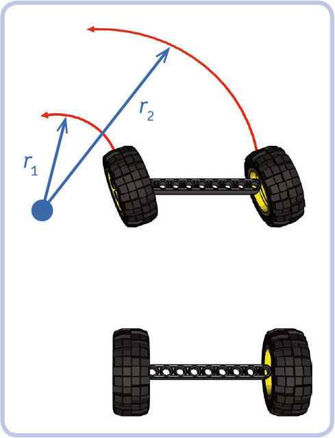
Figure 16-13: The inner and outer wheels of a steered vehicle follow circles of different radii: r2 is equal to r1 plus the width of the vehicle.
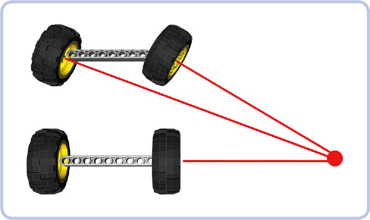
Figure 16-14: Ackermann steering geometry keeps the wheels on the steered axle perpendicular to the center of the turning radius when making a turn.
This geometry, which makes the wheels follow correct radii, is achieved by modifying the steering arms so that they point at the middle of the rear axle, as Figure 16-15 shows.
When it comes to LEGO vehicles, this additional friction and the tire wear are negligible, except for very heavy and large models. The improved handling that comes with Ackermann geometry is advantageous but only noticeable with large vehicles with significant steering lock. Ackermann geometry is important enough to be used in many high-end RC cars, and two official LEGO Technic supercars use it: the 8865 and 8880 sets (shown in Figure 16-16). Both use independent steered suspension, which is also driven in the 8880 set.
Both the 8865 and 8880 sets use special steering arms with shifted pivot points, shown in Figure 16-17. Both are rare pieces by now, but we can build our own custom steering arm using other pieces, as shown in the building instructions on page 226.
There is one more way to achieve Ackermann geometry: We can use a three-piece tie rod with a longer central section and with the two side sections set at an angle, as shown in Figure 16-18. Such a tie rod has little travel, and it should be placed in front of the front axle. Note that with this solution, the steering arms don’t point at the middle of the rear axle, so it’s difficult to see whether the proper geometry is achieved. This solution puts very high forces in the tie rods.

Figure 16-15: A proper Ackermann geometry: The front axle’s steering arms point at the center of the rear axle.

Figure 16-16: The 8865 and 8880 sets are designed with Ackermann geometry in mind.

Figure 16-17: Steering arms from the 8865 (left) and 8880 (right) sets, mounted in suspension arms (blue). Both have shifted pivot points to allow Ackermann geometry; the 8880 arm also allows the wheels to be driven.
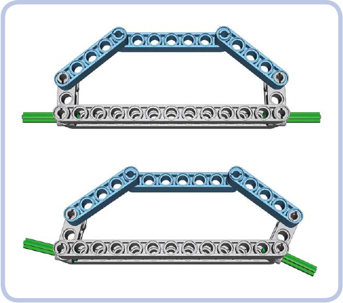
Figure 16-18: Ackermann steering geometry achieved by using a three-piece tie rod with a longer central section
Note that the central gear rack needs to be guided to keep it perpendicular to the chassis.
Ackermann steering geometry was included in the official LEGO sets as an additional technical highlight rather than for its actual advantages. Given the weights and sizes of most LEGO models, the benefits of such a sophisticated solution are negligible. Still, many builders consider including it in a model a great display of skill.
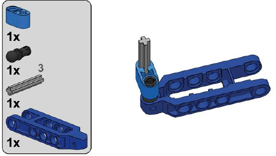
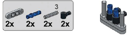
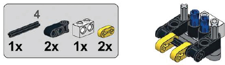
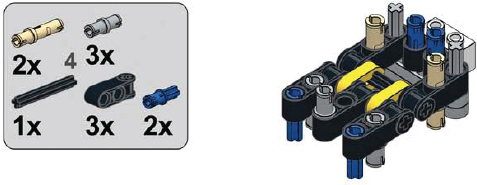
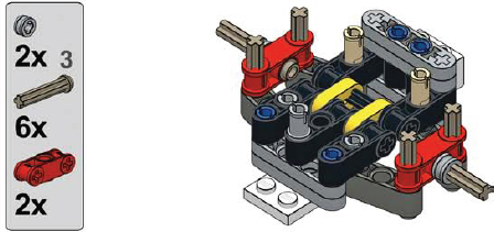
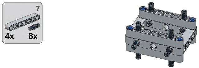
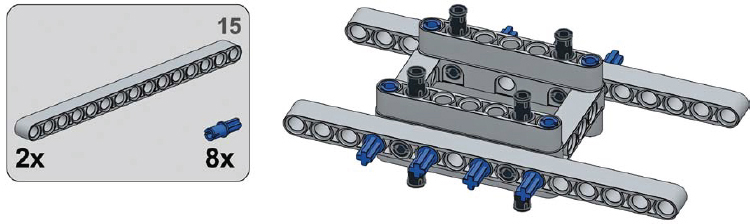
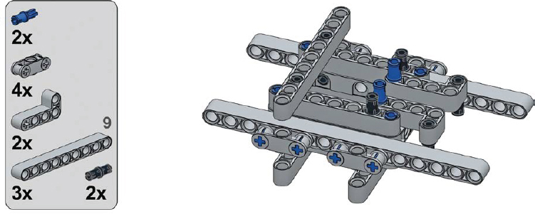
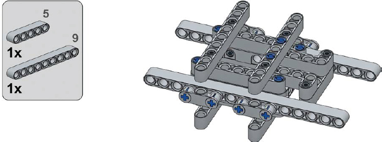
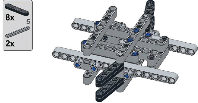
a simple steering arm with Ackermann geometry
1
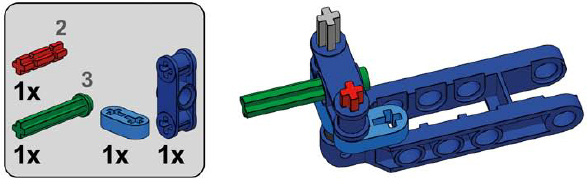
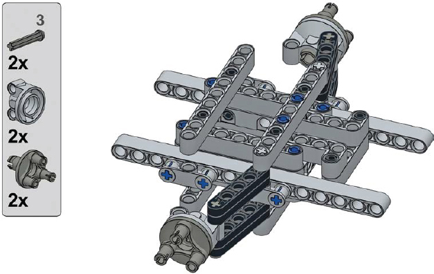
2
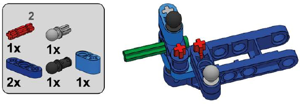
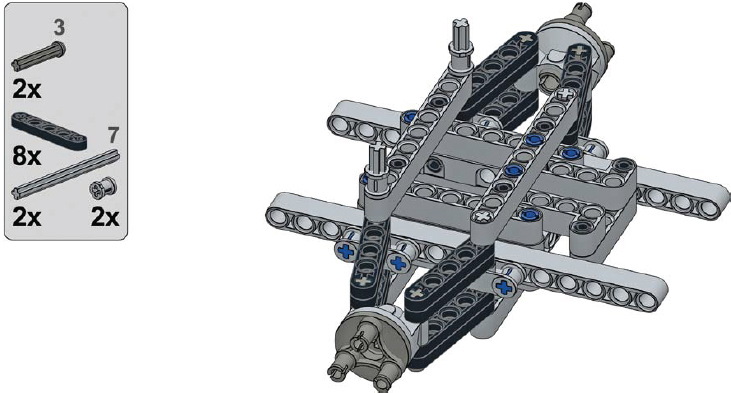
3
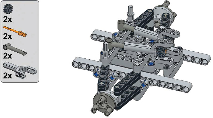
4

convergence of axles
While discussing Ackermann steering geometry, we learned that every vehicle has its center of turning radius. When the wheels are turned, the center is where lines perpendicular to each wheel meet (ignore the outer steered wheels if you use a regular steering geometry), as shown in Figures 16-19 and 16-20. The center can be closer or farther from the vehicle, depending on how much the wheels are turned.
Now, consider a line that points at the center and at the same time is perpendicular to the chassis of the vehicle. In Figure 16-21, that line goes exactly through the rear, fixed axle. No matter how much the steered wheels are turned, this line will always cross the chassis in the same place. We call it the convergence line.
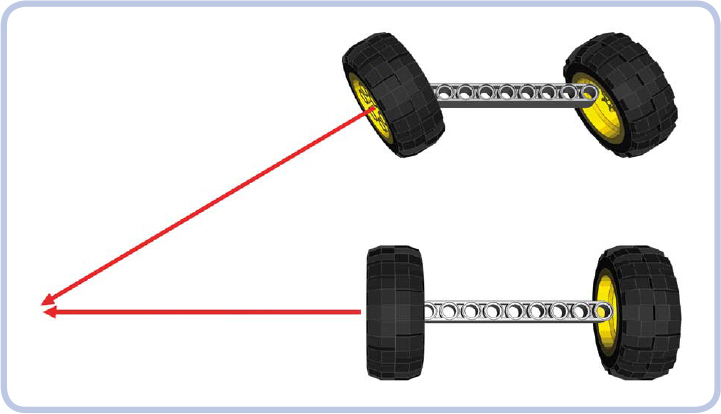
Figure 16-19: The center of turning for a vehicle with regular steering geometry: The outer steered wheel is ignored.
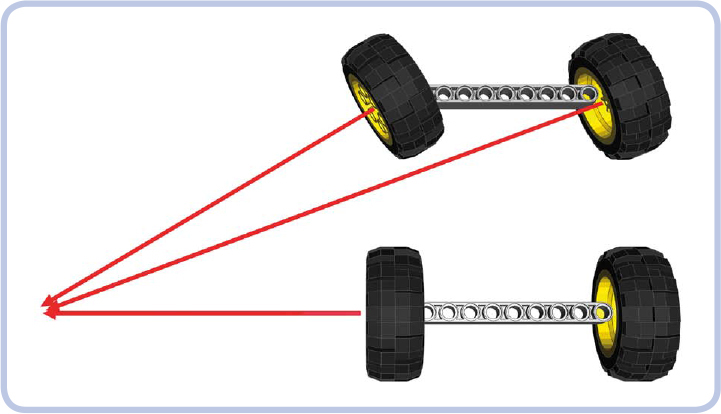
Figure 16-20: The center of turning for a vehicle with Ackermann steering geometry: All wheels “point” at it.
When the axles of a vehicle are convergent, the vehicle turns easily and with little friction. The exact placement of the convergence line depends on the nonsteered axles. For example, when there is one such axle, the convergence line agrees with it; when there are two such axles, the convergence line is exactly between them (as shown in Figure 16-22). When there are three such axles at equal intervals, the convergence line agrees with the middle one, and so on.
When we have more than one steered axle, the convergence line helps to determine the proper spacing between the axles and the difference in their steering locks. For example, if we have steered axles in the front and rear of the vehicle, they should be symmetrical to the convergence line, which means that the front axle should steer in the opposite direction of the rear axle, as shown in Figure 16-23.
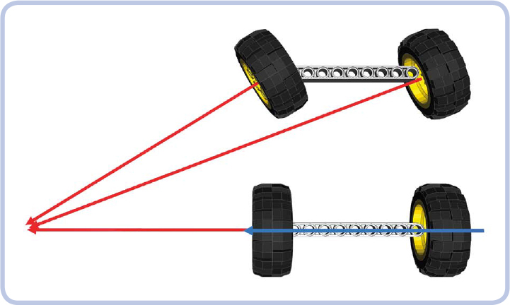
Figure 16-21: Blue marks the convergence line—the line that is perpendicular to the chassis while pointing at the center of turning.

Figure 16-22: For a chassis with a single steered axle and two rear nonsteered ones, the convergence line lies exactly between the rear axles. In this example, since the rear wheels do not point at the rotation center, they will scrub in a turn. This is a big problem for vehicles and trailers with many nonsteered axles. It’s also a big problem for airplanes, which turn very tightly.
The most complex case is when we have two or more steered axles next to one another; to maintain convergence, they need different steering locks. It is possible to calculate this difference, but it involves using trigonometry to calculate an inverse tangent.
Figure 16-24 shows a chassis with two steered axles and one nonsteered axle. We know that in this case, the convergence line agrees with the only nonsteered axle. We need to calculate the relationship between the angles of both steered axles, and to do this, we need to know these angles. This can be done by comparing distances between the steered axles and the convergence line for a given angle of the front wheels. In this example, let’s assume the angle is 45 degrees. As we can see, the front axle is 13 studs away and the middle one is 7 studs away from the convergence line. We need to calculate the relationship between the shorter and longer distances:
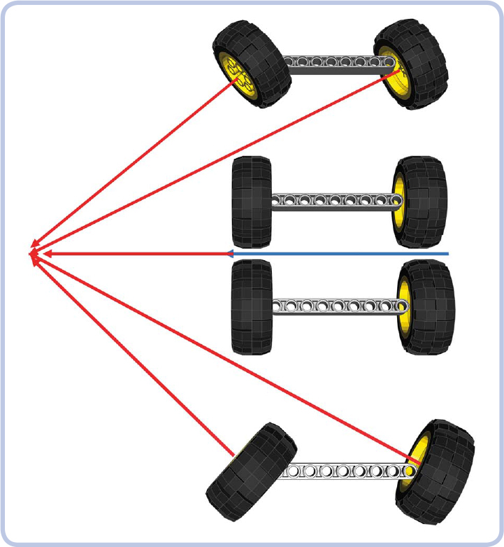
Figure 16-23: If there are steered axles in the front and rear, they should be symmetrical to the convergence line.
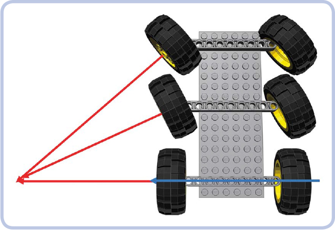
Figure 16-24: The steering locks of the two front axles of this chassis should differ to maintain convergence.
Next, we need to find the inverse tangent (arctangent) for this relationship.
We have just calculated the angle at which the middle axle should be steered, and we know that the angle of the front axle is 45 degrees. Now we need to compare these angles to know the difference between angles and translate it into gearing in the steering system.
We can round the result to 0.6. This means that the middle axle should steer at 0.6, or about 60 percent of the front axle’s angle. Therefore, the steering on the middle axle should be geared down to 0.6 as compared to the front axle. We can do this in two ways:
![]() Use a single steering shaft for both axles but with pinions of different sizes on each rack (see Figure 16-25).
Use a single steering shaft for both axles but with pinions of different sizes on each rack (see Figure 16-25).
![]() Use the same pinions on both axles but with two steering shafts with gearing between them (see Figure 16-26).
Use the same pinions on both axles but with two steering shafts with gearing between them (see Figure 16-26).

Figure 16-25: First method for two axles with different steering locks: a single steering shaft with two pinions of different size
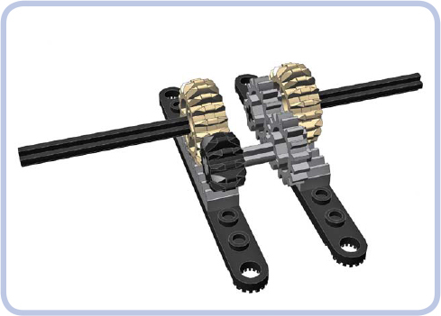
Figure 16-26: Second method for two axles with different steering locks: two identical pinions but two separate steering shafts with gearing between them
Whichever way we choose, it all comes down to the gear sizes. If we use a 20-tooth gear on the front axle, here’s how we calculate the middle one:
20 teeth×0.6 = 12 teeth
As you see from the calculation, we need a 12-tooth gear. When assembling the model, we also need to make sure that the two steered axles are aligned.
Finally, a simple (and math-free!) alternative is to make a simple mock-up of the chassis showing just the distances between axles. You place the mock-up on a sheet of paper, turn the wheels so that they point at the center of the turning radius, and physically draw the lines and measure the angles. If you find any of these methods troublesome, you can always ignore convergence completely. It won’t stop your models from driving or turning—they just won’t handle as well as they would with convergent axles.
steering with virtual pivots
When a wheel is steered, it turns around an axis called the wheel’s steering axis, or simply a pivot (see Chapter 25 for a more detailed explanation). Steering systems perform best when the pivot goes through the center of the wheel, but most LEGO wheels have pivots closer to the wheel’s inner side, which impairs the steering performance of the entire vehicle. This placement also means that LEGO wheels don’t fit under realistic, tight fenders because they need a large margin of free space surrounding them to be steered.
One solution to this problem is to employ a steering system with virtual pivots that use a linkage to turn the wheel as though the pivot were located close to its center, as shown in Figure 16-27. This system works with most wheels. The main disadvantage is that the linkage makes it extremely difficult to add suspension between the chassis and the wheels; however, you can add suspension between the steering system and the rest of the chassis.
Virtual pivots are particularly useful in small-scale models where there is little room between the front wheels and the vehicle’s body. Consider the model in Figure 16-28: It’s very small, and the front fenders almost touch the front wheels. Yet it’s fully remote controlled, and the front wheels can be steered without touching the fenders due to a small version of the virtual pivot steering system.
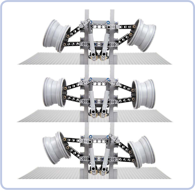
Figure 16-27: A top-down view of a steering system with virtual pivots. The tires have been removed from the rims for clarity.
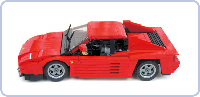
Figure 16-28: My Ferrari Testarossa model is small, at only 37 studs long, yet it has steered front wheels that fit under the front fenders because of the virtual pivot steering system.
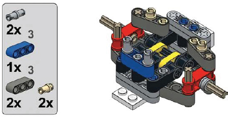
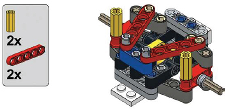
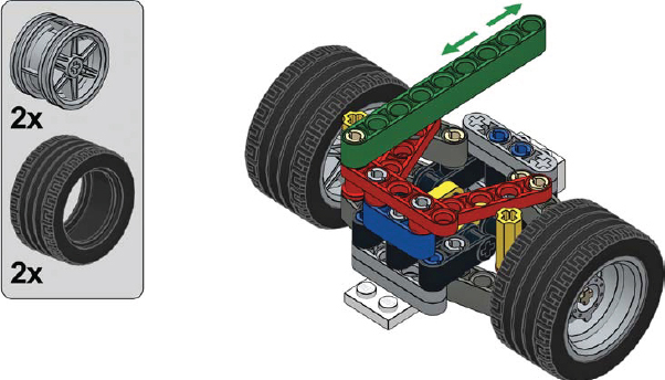
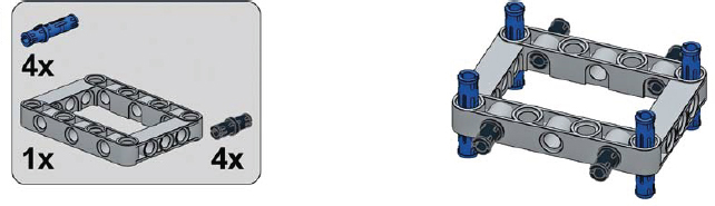
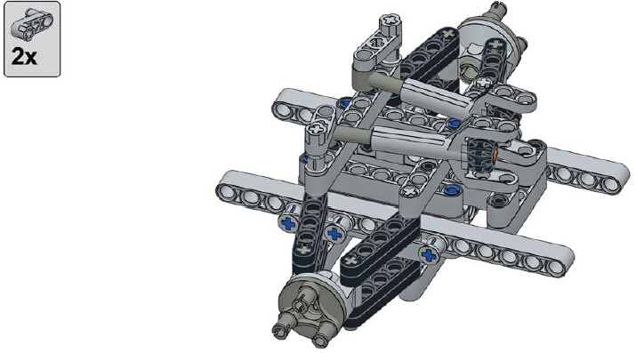
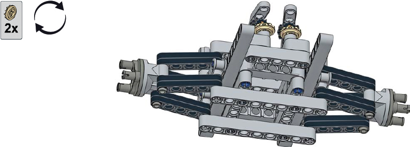
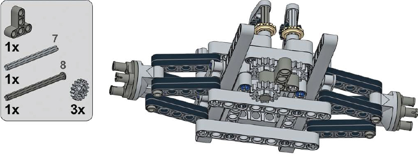
a small virtual pivot steering system
In a small virtual pivot steering system, the wheels are turned by pulling and pushing the green beam (step 8). The system can be used with a motorized linear actuator or directly with a PF Servo motor.
1
2
3
4

5
6
7
8

9
a large virtual pivot steering system
In a large virtual pivot steering system, the wheels are turned by two small linear actuators that are coupled and driven by a single motor. This system is best used with the PF M motor for light models and the PF L motor for heavy models.
1
2
3
4
5
6
7
8
9
10
11
12
13

14
