4
American and European Regulations on Ultrawideband Systems
James D. Taylor
CONTENTS
4.2 U.S. UWB Device Regulations
4.2.1 Source of American UWB Regulations
4.2.2 UWB Device Restrictions from 47 U.S.C
4.2.2.1 Extract of “FCC Regulations Part 15 Radio Frequency Devices”
4.2.2.2 Additional FCC Regulations
4.3 European Union UWB Regulations
4.3.2 History of EU Regulations
4.3.3 Extracts of the EU UWB-Related Regulations
4.3.3.1 EU Permission to Use UWB
4.3.3.2 EU Ground- and Wall-Probing Radar (GPR/WPR) Frequency Spectrum Allocations
4.3.3.3 UWB Low Duty Cycle (LDC) Devices to Ensure the Protection of FWA Systems
4.3.3.4 EU Requirements for Object Discrimination and Characterization of Devices
4.3.3.5 EU Restrictions for Material Sensing Devices
4.3.3.6 Supplementary Regulations for UWB Devices Using Mitigation Techniques
4.3.3.7 EU Requirements for LCD and DAA Devices below 10.6 GHz
4.3.3.8 European Technical Standards Institute UWB Systems Publications
4.1 Introduction
4.1.1 Background
Government regulations regarding the permissible spectra and power levels for ultra-wideband (UWB)-licensed devices aid widespread commercial development and applications. Development of UWB products for export requires reliable information about the permissible radiation limits in the intended market.
4.1.2 Chapter Objectives
This chapter presents the technical parts of American and European regulations on UWB sensors and devices as of January 2010. Government regulations appear verbatim enclosed in quotation marks and are shown in smaller font type.
4.1.3 Warning
Government regulations can change over time. The introduction of new narrowband systems operating in the 1-10-GHz band may cause changes in the permitted radiation power spectrum for UWB devices. Designers must consult the most recent complete relevant regulations to ensure compliance with local and export market restrictions. In most cases, you can find the regulations on Internet for downloading. Assume nothing and work with your country’s telecommunications agencies to ensure local and international compliance.
4.2 U.S. UWB Device Regulations
4.2.1 Source of American UWB Regulations
In 2000, the U.S. Federal Communications Commission (FCC) invited comments from the UWB community regarding usage, interference, and proposed regulation of UWB devices. The received comments resulted in 47 U.S.C. Sections 154, 302a, 303, 304, 307, 336, and 544A [1].
4.2.2 UWB Device Restrictions from 47 U.S.C
Subpart F—Ultra-Wideband Operation to Part 15, Radio Frequency Devices. This section presents the UWB device regulations and related materials regarding measurement procedures. Direct extracts appear in smaller font and quotations marks. Table 4.1 summarizes the sections presented. Note that the regulation numbering omits numbers, but all pertinent sections appear.
4.2.2.1 Extract of “FCC Regulations Part 15 Radio Frequency Devices”
The following Part 15 regulations contain all updates and changes adopted and released by the Commission as of September 20, 2007. However, changes to the rules do not become effective until at least 30 days after they are published in the Federal Register. It is possible that recent changes to these rules may not have been published in the Federal Register and may not yet be effective. In addition, this version contains some directional notes, not themselves contained in the regulations. These directional notes are enclosed by brackets ([]).
TABLE 4.1
Subpart F American UWB Operation Regulations Presented

4.2.2.1.1 Subpart F—Ultra-Wideband Operation (Unlicensed UWB Transmission Systems)
Section 15.501 Scope
This subpart sets out the regulations for unlicensed ultra-wideband transmission systems. Section 15.503 Definitions.
UWB Bandwidth. For the purpose of this subpart, the UWB bandwidth is the frequency band bounded by the points that are 10 dB below the highest radiated emission, as based on the complete transmission system including the antenna. The upper boundary is designated fH and the lower boundary is designated fL. The frequency at which the highest radiated emission occurs is designated fss.
Center frequency. The center frequency, fC, equals (fH - fL)/2.
Fractional bandwidth. The fractional bandwidth equals 2(fH - fL)/(fH + fL).
Ultra-wideband (UWB) transmitter. An intentional radiator that, at any point in time, has a fractional bandwidth equal to or greater than 0.20 or has a UWB bandwidth equal to or greater than 500 MHz, regardless of the fractional bandwidth.
Imaging system. A general category consisting of ground penetrating radar systems, medical imaging systems, wall imaging systems through-wall imaging systems and surveillance systems. As used in this subpart, imaging systems do not include systems designed to detect the location of tags or systems used to transfer voice or data information.
Ground penetrating radar (GPR) system. A field disturbance sensor that is designed to operate only when in contact with, or within one meter of, the ground for the purpose of detecting or obtaining the images of buried objects or determining the physical properties within the ground. The energy from the GPR is intentionally directed down into the ground for this purpose.
Medical imaging system. A field disturbance sensor that is designed to detect the location or movement of objects within the body of a person or animal.
Wall imaging system. A field disturbance sensor that is designed to detect the location of objects contained within a “wall” or to determine the physical properties within the “wall.” The “wall” is a concrete structure, the side of a bridge, the wall of a mine or another physical structure that is dense enough and thick enough to absorb the majority of the signal transmitted by the imaging system. This category of equipment does not include products such as “stud locators” that are designed to locate objects behind gypsum, plaster or similar walls that are not capable of absorbing the transmitted signal.
Through-wall imaging system. A field disturbance sensor that is designed to detect the location or movement of persons or objects that are located on the other side of an opaque structure such as a wall or a ceiling. This category of equipment may include products such as “stud locators” that are designed to locate objects behind gypsum, plaster or similar walls that are not thick enough or dense enough to absorb the transmitted signal.
Surveillance system. A field disturbance sensor used to establish a stationary RF perimeter field that is used for security purposes to detect the intrusion of persons or objects.
EIRP. Equivalent isotropically radiated power, i.e., the product of the power supplied to the antenna and the antenna gain in a given direction relative to an isotropic antenna. The EIRP, in terms of dBm, can be converted to field strength, in dBμV/m at 3 meters, by adding 95.2 dB. As used in this subpart, EIRP refers to the highest signal strength measured in any direction and at any frequency from the UWB device, as tested in accordance with the procedures specified in Sections 15.31(a) and 15.523 of this chapter.
Law enforcement, fire and emergency rescue organizations. As used in this subpart, this refers to those parties eligible to obtain a license from the FCC under the eligibility requirements specified in Section 90.20(a)(1) of this chapter.
Hand held. As used in this subpart, a hand held device is a portable device, such as a lap top computer or a PDA, that is, primarily hand held while being operated and that does not employ a fixed infrastructure.
Section 15.505 Cross Reference
Except where specifically stated otherwise within this subpart, the provisions of Subparts A and B and of Sections 15.201 through 15.204 and Section 15.207 of Subpart C of this part apply to unlicensed UWB intentional radiators. The provisions of Sections 15.35(c) and 15.205 do not apply to devices operated under this subpart. The provisions of Footnote US 246 to the Table of Frequency Allocations contained in Section 2.106 of this chapter does not apply to devices operated under this subpart.
The requirements of Subpart F apply only to the radio transmitter, i.e., the intentional radiator, contained in the UWB device. Other aspects of the operation of a UWB device may be subject to requirements contained elsewhere in this chapter. In particular, a UWB device that contains digital circuitry not directly associated with the operation of the transmitter also is subject to the requirements for unintentional radiators in Subpart B of this chapter. Similarly, an associated receiver that operates (tunes) within the frequency range 30 MHz to 960 MHz is subject to the requirements in Subpart B of this chapter.
Section 15.507 Marketing of UWB Equipment
In some cases, the operation of UWB devices is limited to specific parties, e.g., law enforcement, fire and rescue organizations operating under the auspices of a state or local government. The marketing of UWB devices must be directed solely to parties eligible to operate the equipment. The responsible party, as defined in Section 2.909 of this chapter, is responsible for ensuring that the equipment is marketed only to eligible parties. Marketing of the equipment in any other manner may be considered grounds for revocation of the grant of certification issued for the equipment.
4.2.2.1.2 Extract “Section 15.509 Technical Requirements for Ground Penetrating Radars and Wall Imaging Systems”
The UWB bandwidth of an imaging system operating under the provisions of this section must be below 10.6 GHz.
Operation under the provisions of this section is limited to GPRs and wall imaging systems operated for purposes associated with law enforcement, fire fighting, emergency rescue, scientific research, commercial mining, or construction.
Parties operating this equipment must be eligible for licensing under the provisions of Part 90 of this chapter.
The operation of imaging systems under this section requires coordination, as detailed in Section 15.525 of this part.
A GPR that is designed to be operated while being hand held and a wall imaging system shall contain a manually operated switch that causes the transmitter to cease operation within 10 seconds of being released by the operator. In lieu of a switch located on the imaging system, it is permissible to operate an imaging system by remote control provided the imaging system ceases transmission within 10 seconds of the remote switch being released by the operator.
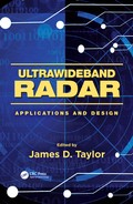
The radiated emissions at or below 960 MHz from a device operating under the provisions of this section shall not exceed the emission levels in Section 15.209. The radiated emissions above 960 MHz from a device operating under the provisions of this section shall not exceed the following average limits when measured using a resolution bandwidth of 1 MHz.
Editor’s Note: The Section 15.209 referenced in 4.2.2.1.2 (d) covers all transmitters operating above 9 kHz. Table 4.2 summarizes the requirements of Section 15.209, which states:
Section 15.209 contains general radiated emission (signal strength) limits that apply to all Part 15 transmitters using frequencies at 9 kHz and above. There are also a number of restricted bands in which low power, non-licensed transmitters are not allowed to operate because of potential interference to sensitive radio communications such as aircraft radionavigation, radio astronomy and search and rescue operations. If a particular transmitter can comply with the general radiated limits, and at the same time avoid operating in one of the restricted bands, then it can use any type of modulation (AM, FM, PCM, etc.) for any purpose. With the exception of intermittent and periodic transmissions, and biomedical telemetry devices, Part 15 transmitters are not permitted to operate in the TV broadcast band.
TABLE 4.2
Section 15.209 Transmitter Restrictions
| Frequency Band (kHz) | Type of Use | Emission Limit |
| 9-45 | Cable locating equipment | 10 Ws peak output power |
| 9-45 | Any | 2400/f(kHz) μV/m @ 300 m |
| 45-90 | Cable locating equipment | 1 W peak output power |
Source: Federal Communications Commission (FCC) 02–48. Revision of part 15 of the commission’s rules regarding ultra-wideband transmission systems. ET Docket 98-153. Released April 22, 2002.

FIGURE 4.1
Radiated power and spectrum limits of American FCC 15.509 regulations for UWB ground-penetrating and through-wall imaging radar. (Adapted from Federal Communications Commission (FCC) 02-48. Revision of part 15 of the commission’s rules regarding ultra-wideband transmission systems. ET Docket 98-153. Released April 22, 2002.)
Figure 4.1 summarizes the FCC restriction for GPR and WPR transmitters equivalent isotropically radiated power (EIRP) measured with a 1-MHz bandwidth:
For UWB devices where the frequency at which the highest radiated emission occurs, fM, is above 960 MHz, there is a limit on the peak level of the emissions contained within a 50 MHz bandwidth centered on fM. That limit is 0 dBm EIRP. It is acceptable to employ a different resolution bandwidth, and a correspondingly different peak emission limit, following the procedures described in Section 15.521.
4.2.2.1.3 Extract “Section 15.510 Technical Requirements for Through-Wall Imaging Systems”
The UWB bandwidth of an imaging system operating under the provisions of this section must be below 960 MHz or the center frequency, fC, and the frequency at which the highest radiated emission occurs, fM, must be contained between 1990 MHz and 10600 MHz.
Operation under the provisions of this section is limited to through-wall imaging systems operated by law enforcement, emergency rescue or firefighting organizations that are under the authority of a local or state government.
For through-wall imaging systems operating with the UWB bandwidth below 960 MHz:
Parties operating this equipment must be eligible for licensing under the provisions of Part 90 of this chapter.
The operation of these imaging systems requires coordination, as detailed in Section 15.525.
The imaging system shall contain a manually operated switch that causes the transmitter to cease operation within 10 seconds of being released by the operator. In lieu of a switch located on the imaging system, it is permissible to operate an imaging system by remote control provided the imaging system ceases transmission within 10 seconds of the remote switch being released by the operator.
The radiated emissions at or below 960 MHz shall not exceed the emission levels in Section 15.209. The radiated emissions above 960 MHz shall not exceed the following average limits when measured using a resolution bandwidth of 1 MHz:
Figure 4.2 summarizes the EIRP limits for the through-wall imaging systems.

FIGURE 4.2
Measured radiated power and spectrum limits of American FCC 15.510 regulations for through-wall UWB imaging systems. (Adapted from Federal Communications Commission (FCC) 02-48. Revision of part 15 of the commission’s rules regarding ultra-wideband transmission systems. ET Docket 98-153. Released April 22, 2002.)
For equipment operating with fC and fM between 1990 MHz and 10600 MHz:
Parties operating this equipment must hold a license issued by the Federal Communications Commission to operate a transmitter in the Public Safety Radio Pool under Part 90 of this chapter. The license may be held by the organization for which the UWB operator works on a paid or volunteer basis.
This equipment may be operated only for law enforcement applications, the providing of emergency services, and necessary training operations.
The radiated emissions at or below 960 MHz shall not exceed the emission levels in Section 15.209 of this chapter. The radiated emissions above 960 MHz shall not exceed the following average limits when measured using a resolution bandwidth of 1 MHz.
Figure 4.3 summarizes the spectrum requirements for special through-wall systems operating between 1990 and 10,600 MHz.
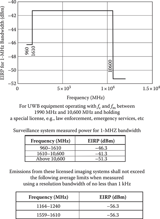
FIGURE 4.3
Measured radiated power and spectrum limits of American FCC 15.510 regulations for through-wall imaging systems UWB spectrum for systems operating between 1990 and 10,600 MHz. (Adapted from Federal Communications Commission (FCC) 02-48. Revision of part 15 of the commission’s rules regarding ultra-wideband transmission systems. ET Docket 98-153. Released April 22, 2002.)(4) There is a limit on the peak level of the emissions contained within a 50 MHz bandwidth centered on the frequency at which the highest radiated emission occurs, fM. That limit is 0 dBm EIRP. It is acceptable to employ a different resolution bandwidth, and a correspondingly different peak emission limit, following the procedures described in Section 15.521.
Through-wall imaging systems operating under the provisions of this section shall bear the following or similar statement in a conspicuous location on the device:
Operation of this device is restricted to law enforcement, emergency rescue and firefighter personnel. Operation by any other party is a violation of 47 U.S.C. 301 and could subject the operator to serious legal penalties.
4.2.2.1.4 Extract “Section 15.511 Technical Requirements for Surveillance Systems”
The UWB bandwidth of an imaging system operating under the provisions of this section must be contained between 1990 MHz and 10,600 MHz.
“Operation under the provisions of this section is limited to fixed surveillance systems operated by law enforcement, fire or emergency rescue organizations or by manufacturers licensees, petroleum licensees or power licensees as defined in Section 90.7 of this chapter.
Parties operating under the provisions of this section must be eligible for licensing under the provisions of Part 90 of this chapter.
The operation of imaging systems under this section requires coordination, as detailed in Section 15.525.
The radiated emissions at or below 960 MHz from a device operating under the provisions of this section shall not exceed the emission levels in Section 15.209. The radiated emissions above 960 MHz from a device operating under the provisions of this section shall not exceed the following average limits when measured using a resolution bandwidth of 1 MHz.
Figure 4.4 summarizes the requirements for UWB surveillance systems.
There is a limit on the peak level of the emissions contained within a 50 MHz bandwidth centered on the frequency at which the highest radiated emission occurs, fM. That limit is 0 dBm EIRP. It is acceptable to employ a different resolution bandwidth, and a correspondingly different peak emission limit, following the procedures described in Section 15.521.
Imaging systems operating under the provisions of this section shall bear the following or similar statement in a conspicuous location on the device:
Operation of this device is restricted to law enforcement, fire and rescue officials, public utilities, and industrial entities. Operation by any other party is a violation of 47 U.S.C. 301 and could subject the operator to serious legal penalties.
4.2.2.1.5 Extract “Section 15.513 Technical Requirements for Medical Imaging Systems”
The UWB bandwidth of an imaging system operating under the provisions of this section must be contained between 3100 MHz and 10,600 MHz.
Operation under the provisions of this section is limited to medical imaging systems used at the direction of, or under the supervision of, a licensed health care practitioner. The operation of imaging systems under this section requires coordination, as detailed in Section 15.525. A medical imaging system shall contain a manually operated switch that causes the transmitter to cease operation within 10 seconds of being released by the operator. In lieu of a switch located on the imaging system, it is permissible to operate an imaging system by remote control provided the imaging system ceases transmission within 10 seconds of the remote switch being released by the operator.

FIGURE 4.4
Measured radiated power and spectrum limits of American FCC 15.510 regulations for surveillance system’s UWB spectrum limits for special systems operated by law enforcement, fire, or emergency rescue organizations, or other special users including manufacturers, petroleum licensees, or power licensees. (Adapted from Federal Communications Commission (FCC) 02-48. Revision of part 15 of the commission’s rules regarding ultra-wideband transmission systems. ET Docket 98-153. Released April 22, 2002.)
The radiated emissions at or below 960 MHz from a device operating under the provisions of this section shall not exceed the emission levels in Section 15.209. The radiated emissions above 960 MHz from a device operating under the provisions of this section shall not exceed the following average limits when measured using a resolution bandwidth of 1 MHz.
Figure 4.5 summarizes the requirements for UWB medical imaging systems.
(c) There is a limit on the peak level of the emissions contained within a 50 MHz bandwidth centered on the frequency at which the highest radiated emission occurs, fM. That limit is 0 dBm EIRP. It is acceptable to employ a different resolution bandwidth, and a correspondingly different peak emission limit, following the procedures described in Section 15.521.
4.2.2.1.6 Extract “Section 15.515 Technical Requirements for Vehicular Radar Systems”
Operation under the provisions of this section is limited to UWB field disturbance sensors mounted in terrestrial transportation vehicles. These devices shall operate only when the vehicle is operating, e.g., the engine is running. Operation shall occur only upon specific activation, such as upon starting the vehicle, changing gears, or engaging a turn signal.

FIGURE 4.5
Measured radiated power and spectrum limits of American FCC 15.510 regulations for medical imaging systems UWB measured spectrum. UWB measured radiated spectrum limits. Emissions must be contained between 3100 MHz and 10,600 MHz. (Adapted from Federal Communications Commission (FCC) 02-48. Revision of part 15 of the commission’s rules regarding ultra-wideband transmission systems. ET Docket 98-153. Released April 22, 2002.)The UWB bandwidth of a vehicular radar system operating under the provisions of this section shall be contained between 22 GHz and 29 GHz. In addition, the center frequency, fC, and the frequency at which the highest level emission occurs, fM, must be greater than 24.075 GHz.
Following proper installation, vehicular radar systems shall attenuate any emissions within the 23.6-24.0 GHz band that appear 38 degrees or greater above the horizontal plane by 25 dB below the limit specified in paragraph (d) of this section. For equipment authorized, manufactured or imported on or after January 1, 2005, this level of attenuation shall be 25 dB for any emissions within the 23.6-24.0 GHz band that appear 30 degrees or greater above the horizontal plane. For equipment authorized, manufactured or imported on or after January 1, 2010, this level of attenuation shall be 30 dB for any emissions within the 23.6-24.0 GHz band that appear 30 degrees or greater above the horizontal plane. For equipment authorized, manufactured or imported on or after January 1, 2014, this level of attenuation shall be 35 dB for any emissions within the 23.6-24.0 GHz band that appear 30 degrees or greater above the horizontal plane. This level of attenuation can be achieved through the antenna directivity, through a reduction in output power or any other means.
The radiated emissions at or below 960 MHz from a device operating under the provisions of this section shall not exceed the emission levels in Section 15.209. The radiated emissions above 960 MHz from a device operating under the provisions of this section shall not exceed the following average limits when measured using a resolution bandwidth of 1 MHz.
Figure 4.6 summarizes the requirements for UWB vehicular systems.
(f) There is a limit on the peak level of the emissions contained within a 50 MHz bandwidth centered on the frequency at which the highest radiated emission occurs, fM. That limit is 0 dBm EIRP. It is acceptable to employ a different resolution bandwidth, and a correspondingly different peak emission limit, following the procedures described in Section 15.521.
(g) The emission levels from devices operating under the provisions of this section that employ gated transmissions may be measured with the gating active. Measurements made in this manner shall be repeated over multiple sweeps with the analyzer set for maximum hold until the amplitude stabilizes.
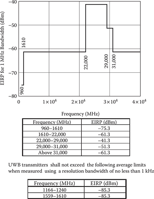
FIGURE 4.6
Measured radiated power and spectrum limits of American FCC 15.510 regulations for vehicular systems UWB spectrum requirements. Limited to UWB field disturbance sensors mounted in terrestrial vehicles, these devices shall operate only when the vehicle is operating, for example, the engine is running. Operation shall occur only upon specific activation, such as upon starting the vehicle, changing gears, or engaging a turn signal. (Adapted from Federal Communications Commission (FCC) 02-48. Revision of part 15 of the commission’s rules regarding ultra-wideband transmission systems. ET Docket 98-153. Released April 22, 2002.)
4.2.2.1.7 Extract “Section 15.517 Technical Requirements for Indoor UWB Systems”
Operation under the provisions of this section is limited to UWB transmitters employed solely for indoor operation.
Indoor UWB devices, by the nature of their design, must be capable of operation only indoors. The necessity to operate with a fixed indoor infrastructure, e.g., a transmitter that must be connected to the AC power lines, may be considered sufficient to demonstrate this.
The emissions from equipment operated under this section shall not be intentionally directed outside of the building in which the equipment is located, such as through a window or a doorway, to perform an outside function, such as the detection of persons about to enter a building.
The use of outdoor mounted antennas, e.g., antennas mounted on the outside of a building or on a telephone pole, or any other outdoors infrastructure is prohibited.
Field disturbance sensors installed inside of metal or underground storage tanks are considered to operate indoors provided the emissions are directed towards the ground.
A communications system shall transmit only when the intentional radiator is sending information to an associated receiver.
The UWB bandwidth of a UWB system operating under the provisions of this section must be contained between 3100 MHz and 10,600 MHz.
The radiated emissions at or below 960 MHz from a device operating under the provisions of this section shall not exceed the emission levels in Section 15.209. The radiated emissions above 960 MHz from a device operating under the provisions of this section shall not exceed the following average limits when measured using a resolution bandwidth of 1 MHz:
Figure 4.7 summarizes the requirements for indoor UWB systems.
(d) There is a limit on the peak level of the emissions contained within a 50 MHz bandwidth centered on the frequency at which the highest radiated emission occurs, fM. That limit is 0 dBm EIRP. It is acceptable to employ a different resolution bandwidth, and a correspondingly different peak emission limit, following the procedures described in Section 15.521.
(f) UWB systems operating under the provisions of this section shall bear the following or similar statement in a conspicuous location on the device or in the instruction manual supplied with the device:
This equipment may only be operated indoors. Operation outdoors is in violation of 47 U.S.C. 301 and could subject the operator to serious legal penalties.
4.2.2.1.8 “Section 15.519 Technical Requirements for Handheld UWB Systems”
UWB devices operating under the provisions of this section must be hand held, i.e., they are relatively small devices that are primarily hand held while being operated and do not employ a fixed infrastructure.
A UWB device operating under the provisions of this section shall transmit only when it is sending information to an associated receiver. The UWB intentional radiator shall cease transmission within 10 seconds unless it receives an acknowledgement from the associated receiver that its transmission is being received. An acknowledgment of reception must continue to be received by the UWB intentional radiator at least every 10 seconds or the UWB device must cease transmitting.

FIGURE 4.7
Measured radiated power and spectrum limits of American FCC 15.510 regulations for indoor UWB systems measured spectrum limits. Intended for systems operating with a fixed indoor infrastructure without any intentional outside emissions. (Adapted from 47 U.S.C. Sections 154, 302a, 303, 304, 307, 336, and 544A.)The use of antennas mounted on outdoor structures, e.g., antennas mounted on the outside of a building or on a telephone pole, or any fixed outdoors infrastructure is prohibited. Antennas may be mounted only on the hand held UWB device.
UWB devices operating under the provisions of this section may operate indoors or outdoors.
The UWB bandwidth of a device operating under the provisions of this section must be contained between 3100 MHz and 10,600 MHz.
The radiated emissions at or below 960 MHz from a device operating under the provisions of this section shall not exceed the emission levels in Section 15.209. The radiated emissions above 960 MHz from a device operating under the provisions of this section shall not exceed the following average limits when measured using a resolution bandwidth of 1 MHz
Figure 4.8 summarizes the requirements for handheld UWB devices.

FIGURE 4.8
Measured radiated power and spectrum limits of American FCC 15.510 regulations for handheld device UWB measured spectrum limits. Intended for small handheld devices operating indoors or outdoors without any fixed infrastructure. (Adapted from Federal Communications Commission (FCC) 02-48. Revision of part 15 of the commission’s rules regarding ultra-wideband transmission systems. ET Docket 98-153. Released April 22, 2002.)
(e) There is a limit on the peak level of the emissions contained within a 50 MHz bandwidth centered on the frequency at which the highest radiated emission occurs, fM. That limit is 0 dBm EIRP. It is acceptable to employ a different resolution bandwidth, and a correspondingly different peak emission limit, following the procedures described in Section 15.521.
4.2.2.1.9 Extract “Section 15.521 Technical Requirements Applicable to All UWB Devices”
UWB devices may not be employed for the operation of toys. Operation onboard an aircraft, a ship or a satellite is prohibited.
Manufacturers and users are reminded of the provisions of Sections 15.203 and 15.204.
Emissions from digital circuitry used to enable the operation of the UWB transmitter shall comply with the limits in Section 15.209 of this chapter, rather than the limits specified in this subpart, provided it can be clearly demonstrated that those emissions from the UWB device are due solely to emissions from digital circuitry contained within the transmitter and that the emissions are not intended to be radiated from the transmitter’s antenna. Emissions from associated digital devices, as defined in Section 15.3(k) of this chapter, e.g., emissions from digital circuitry used to control additional functions or capabilities other than the UWB transmission, are subject to the limits contained in Subpart B of Part 15 of this chapter.
Within the tables in Sections 15.509, 15.511, 15.513, 15.515, 15.517, and 15.519, the tighter emission limit applies at the band edges. Radiated emission levels at and below 960 MHz are based on measurements employing a CISPR quasi-peak detector. Radiated emission levels above 960 MHz are based on RMS average measurements over a 1 MHz resolution bandwidth. The RMS average measurement is based on the use of a spectrum analyzer with a resolution bandwidth of 1 MHz, an RMS detector, and a 1 millisecond or less averaging time. Unless otherwise stated, if pulse gating is employed where the transmitter is quiescent for intervals that are long compared to the nominal pulse repetition interval, measurements shall be made with the pulse train gated on. Alternative measurement procedures may be considered by the Commission.
[The reference to a 1 millisecond or less averaging time denotes the integration time period for each bin on the spectrum analyzer. The analyzer sweep time/number of bins must not exceed one millisecond. Trace averaging should not be used in making the RMS measurements.]
The frequency at which the highest radiated emission occurs, fM, must be contained within the UWB bandwidth.
Imaging systems may be employed only for the type of information exchange described in their specific definitions contained in Section 15.503. The detection of tags or the transfer or data or voice information is not permitted under the standards for imaging systems.
When a peak measurement is required, it is acceptable to use a resolution bandwidth other than the 50 MHz specified in this subpart. This resolution bandwidth shall not be lower than 1 MHz or greater than 50 MHz, and the measurement shall be centered on the frequency at which the highest radiated emission occurs, fM. If a resolution bandwidth other than 50 MHz is employed, the peak EIRP limit shall be 20 log (RBW/50) dBm where RBW is the resolution bandwidth in megahertz that is employed. This may be converted to a peak field strength level at 3 meters using E(dBμV/m) = P(dBm EIRP). If RBW is greater than 3 MHz, the application for certification filed with the Commission must contain a detailed description of the test procedure, calibration of the test setup, and the instrumentation employed in the testing.
The highest frequency employed in Section 15.33 to determine the frequency range over which radiated measurements are made shall be based on the center frequency, f, unless a higher frequency is generated within the UWB device. For measuring emission levels, the spectrum shall be investigated from the lowest frequency generated in the UWB transmitter, without going below 9 kHz, up to the frequency range shown in Section 15.33(a) or up to fC + 3/(pulse width in seconds) whichever is higher. There is no requirement to measure emissions beyond 40 GHz provided fC is less than 10 GHz; beyond 100 GHz if fC is at or above 10 GHz and below 30 GHz; or beyond 200 GHz if fC is at or above 30 GHz.
The prohibition in Sections 2.201(f) and 15.5(d) of this chapter against Class B (damped wave) emissions does not apply to UWB devices operating under this subpart.
Responsible parties are reminded of the other standards and requirements incorporated by reference in Section 15.505, such as a limit on emissions conducted onto the AC power lines.
4.2.2.1.10 Extract “Section 15.523 Measurement Procedures”
Measurements shall be made in accordance with the procedures specified by the Commission. Section 15.525 Coordination requirements.
UWB imaging systems require coordination through the FCC before the equipment may be used. The operator shall comply with any constraints on equipment usage resulting from this coordination.
The users of UWB imaging devices shall supply operational areas to the FCC Office of Engineering and Technology, which shall coordinate this information with the Federal Government through the National Telecommunications and Information Administration. The information provided by the UWB operator shall include the name, address and other pertinent contact information of the user, the desired geographical area(s) of operation, and the FCC ID number and other nomenclature of the UWB device. If the imaging device is intended to be used for mobile applications, the geographical area(s) of operation may be the state(s) or county(ies) in which the equipment will be operated. The operator of an imaging system used for fixed operation shall supply a specific geographical location or the address at which the equipment will be operated. This material shall be submitted to the following address:
Frequency Coordination Branch
OET Federal Communications Commission
445 12th Street, SW
Washington, D.C. 20554
Attn: UWB Coordination
The manufacturers, or their authorized sales agents, must inform purchasers and users of their systems of the requirement to undertake detailed coordination of operational areas with the FCC prior to the equipment being operated.
Users of authorized, coordinated UWB systems may transfer them to other qualified users and to different locations upon coordination of change of ownership or location to the FCC and coordination with existing authorized operations.
The FCC/NTIA coordination report shall identify those geographical areas within which the operation of an imaging system requires additional coordination or within which the operation of an imaging system is prohibited. If additional coordination is required for operation within specific geographical areas, a local coordination contact will be provided. Except for operation within these designated areas, once the information requested on the UWB imaging system is submitted to the FCC no additional coordination with the FCC is required provided the reported areas of operation do not change. If the area of operation changes, updated information shall be submitted to the FCC following the procedure in paragraph (b) of this section.
(e) The coordination of routine UWB operations shall not take longer than 15 business days from the receipt of the coordination request by NTIA. Special temporary operations may be handled with an expedited turn-around time when circumstances warrant. The operation of UWB systems in emergency situations involving the safety of life or property may occur without coordination provided a notification procedure, similar to that contained in Section 2.405(a) through (e) of this chapter, is followed by the UWB equipment user.
4.2.2.1.11 Extract “Section 15.615 General Administrative Requirements”
The provisions of subparts A and B of this part apply to Access BPL devices, except where specifically noted. The provisions of subparts C-F of this part do not apply to Access (Broadband over Power Lines) BPL devices except where specifically noted.
The requirements of this subpart apply only to the radio circuitry that is used to provide carrier current operation for the Access BPL device. Other aspects of the operation of an Access BPL device may be subject to requirements contained elsewhere in this chapter. In particular, an Access BPL device that includes digital circuitry that is not used solely to enable the operation of the radio frequency circuitry used to provide carrier current operation also is subject to the requirements for unintentional radiators in subpart B.
4.2.2.2 Additional FCC Regulations
The FCC regulations for UWB systems reference other parts of Section 15 of 47 U.S.C. Sections 154, 302a, 303, 304, 307, 336, and 544A [1]. This section contains those portions that the UWB systems designer must know. Table 4.3 lists the references included here and describes them.
4.2.2.2.1 Extract Section 15.5—“General Conditions of Operation”
Persons operating intentional or unintentional radiators shall not be deemed to have any vested or recognizable right to continued use of any given frequency by virtue of prior registration or certification of equipment, or, for power line carrier systems, on the basis of prior notification of use pursuant to Section 90.63(g) of this chapter. [Should reference Section 90.35(g).]
Operation of an intentional, unintentional, or incidental radiator is subject to the conditions that no harmful interference is caused and that interference must be accepted that may be caused by the operation of an authorized radio station, by another intentional or unintentional radiator, by industrial, scientific and medical (ISM) equipment, or by an incidental radiator.
The operator of a radio frequency device shall be required to cease operating the device upon notification by a Commission representative that the device is causing harmful interference. Operation shall not resume until the condition causing the harmful interference has been corrected. Intentional radiators that produce Class B emissions (damped wave) are prohibited.
4.2.2.2.2 Extract of “FCC Section 15.31 Measurement Standards”
The following measurement procedures are used by the Commission to determine compliance with the technical requirements in this part. Except where noted, copies of these procedures are available from the Commission’s current duplicating contractor whose name and address are available from the Commission’s Consumer and Governmental Affairs Bureau at 1-888-CALL FCC (1-888-225-5322).
FCC/OET MP-2: Measurement of UHF Noise Figures of TV Receivers.
Unlicensed Personal Communication Service (UPCS) devices are to be measured for compliance using ANSI C63.17-1998: “Methods of Measurement of the Electromagnetic and Operational Compatibility of Unlicensed Personal Communications Services (UPCS) Devices”, (incorporated by reference, see § 15.38). This incorporation by reference was approved by the Director of the Federal Register in accordance with 5 U.S.C. 552(a) and 1 CFR Part 51
TABLE 4.3
Other FCC Regulations Applicable to UWB Systems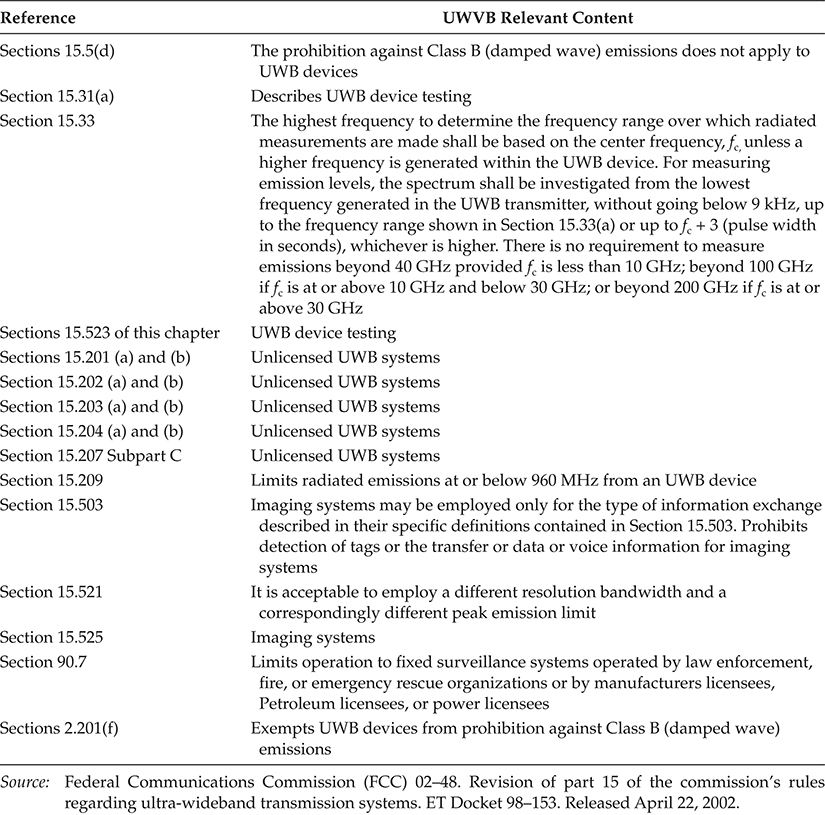
Other intentional and unintentional radiators are to be measured for compliance using the following procedure excluding sections 4.1.5.2, 5.7, 9 and 14: ANSI C63.4-2003: “Methods of Measurement of Radio-Noise Emissions from Low-Voltage Electrical and Electronic Equipment in the Range of 9 kHz to 40 GHz” (incorporated by reference, see § 15.38). This incorporation by reference was approved by the Director of the Federal Register in accordance with 5 U.S.C. 552(a) and 1 CFR Part 51.
NOTE to Paragraph (a)(3): Digital devices tested to show compliance with the provisions of § § 15.107(e) and 15.109(g) must be tested following the ANSI C63.4 procedure described in paragraph (a)(3) of this section.
“[As stated in the adopting R&O, ANSI C63.4 is not used for measurements below 30 MHz.]”
4.2.2.2.3 Extract “Section 15.33 Frequency Range of Radiated Measurements”
Unless otherwise noted in the specific rule section under which the equipment operates for an intentional radiator the spectrum shall be investigated from the lowest radio frequency signal generated in the device, without going below 9 kHz, up to at least the frequency shown in this paragraph:
If the intentional radiator operates below 10 GHz: to the tenth harmonic of the highest fundamental frequency or to 40 GHz, whichever is lower.
If the intentional radiator operates at or above 10 GHz and below 30 GHz: to the fifth harmonic of the highest fundamental frequency or to 100 GHz, whichever is lower.
If the intentional radiator operates at or above 30 GHz: to the fifth harmonic of the highest fundamental frequency or to 200 GHz, whichever is lower, unless specified otherwise elsewhere in the rules.
If the intentional radiator contains a digital device, regardless of whether this digital device controls the functions of the intentional radiator or the digital device is used for additional control or function purposes other than to enable the operation of the intentional radiator, the frequency range shall be investigated up to the range specified in paragraphs (a)(1)-(a)(3) of this section or the range applicable to the digital device, as shown in paragraph (b)(1) of this Section, whichever is the higher frequency range of investigation.”
For unintentional radiators:
Except as otherwise indicated in paragraphs (b)(2) or (b)(3), for an unintentional radiator, including a digital device, the spectrum shall be investigated from the lowest radio frequency signal generated or used in the device, without going below the lowest frequency for which a radiated emission limit is specified, up to the frequency shown in the following table” (See Table 4.4.)
(5) Except for a CB receiver, a receiver employing superheterodyne techniques shall be investigated from 30 MHz up to at least the second harmonic of the highest local oscillator frequency generated in the device. If such receiver is controlled by a digital device, the frequency range shall be investigated up to the higher of the second harmonic of the highest local oscillator frequency generated in the device or the upper frequency of the measurement range specified for the digital device in paragraph (b)(1) of this Section.
TABLE 4.4
FCC Unintentional Radiation Measurement RangesHighest Frequency Generated or Used in the Device or on Which the Device Operates or Tunes (MHz) Upper Frequency of Measurement Range (mHz) Below 1.705 30 1.705-1.08 1000 108-500 2000 500-1000 5000 Above 1000 Fifth harmonic of the highest frequency or 40 GHz, whichever is lower Source: Federal Communications Commission (FCC) 02–48. Revision of part 15 of the commission’s rules regarding ultra-wideband transmission systems. ET Docket 98–153. Released April 22, 2002.
The above specified frequency ranges of measurements apply to the measurement of radiated emissions and, in the case of receivers, the measurement to demonstrate compliance with the antenna conduction limits specified in Section 15.111. The frequency range of measurements for AC power line conducted limits is specified in Sections 15.107 and 15.207 and applies to all equipment subject to those regulations. In some cases, depending on the frequency(ies) generated and used by the equipment, only signals conducted onto the AC power lines are required to be measured.
Particular attention should be paid to harmonics and subharmonics of the fundamental frequency as well as to those frequencies removed from the fundamental by multiples of the oscillator frequency. Radiation at the frequencies of multiplier stages should also be checked.
4.2.2.2.4 Extract of “Section 15.201 Equipment Authorization Requirement”
Intentional radiators operated as carrier current systems, devices operated under the provisions of §§ 15.211, 15.213 and 15.221, and devices operating below 490 kHz in which all emissions are at least 40 dB below the limits in Section 15.209 shall be verified pursuant to the procedures in Subpart J of Part 2 of this Chapter prior to marketing.
Except as otherwise exempted in paragraph (c) of this Section and in Section 15.23 of this Part, all intentional radiators operating under the provisions of this Part shall be certificated by the Commission pursuant to the procedures in Subpart J of Part 2 of this Chapter prior to marketing.
For devices such as perimeter protection systems which, in accordance with Section 15.31(d), are required to be measured at the installation site, each application for certification must be accompanied by a statement indicating that the system has been tested at three installations and found to comply at each installation. Until such time as certification is granted, a given installation of a system that was measured for the submission for certification will be considered to be in compliance with the provisions of this Chapter, including the marketing regulations in Subpart I of Part 2, if tests at that installation show the system to be in compliance with the relevant technical requirements. Similarly, where measurements must be performed on site for equipment subject to verification, a given installation that has been verified to demonstrate compliance with the applicable standards will be considered to be in compliance with the provisions of this Chapter, including the marketing regulations in Subpart I of Part 2.
4.2.2.2.5 Extract “Section 15.202 Certified Operating Frequency Range”
Client devices that operate in a master/client network may be certified if they have the capability of operating outside permissible Part 15 frequency bands, provided they operate on only permissible Part 15 frequencies under the control of the master device with which they communicate. Master devices marketed within the United States must be limited to operation on permissible Part 15 frequencies. Client devices that can also act as master devices must meet the requirements of a master device. For the purposes of this section, a master device is defined as a device operating in a mode in which it has the capability to transmit without receiving an enabling signal. In this mode it is able to select a channel and initiate a network by sending enabling signals to other devices. A network always has at least one device operating in master mode. A client device is defined as a device operating in a mode in which the transmissions of the device are under control of the master. A device in client mode is not able to initiate a network.
4.2.2.2.6 Extract “Section 15.203 Antenna Requirement”
An intentional radiator shall be designed to ensure that no antenna other than that furnished by the responsible party shall be used with the device. The use of a permanently attached antenna or of an antenna that uses a unique coupling to the intentional radiator shall be considered sufficient to comply with the provisions of this Section. The manufacturer may design the unit so that a broken antenna can be replaced by the user, but the use of a standard antenna jack or electrical connector is prohibited. This requirement does not apply to carrier current devices or to devices operated under the provisions of Sections 15.211, 15.213, 15.217, 15.219, or 15.221. Further, this requirement does not apply to intentional radiators that must be professionally installed, such as perimeter protection systems and some field disturbance sensors, or to other intentional radiators which, in accordance with Section 15.31(d), must be measured at the installation site. However, the installer shall be responsible for ensuring that the proper antenna is employed so that the limits in this Part are not exceeded.
4.2.2.2.7 Extract “Section 15.204 External Radio Frequency Power Amplifiers and Antenna Modifications”
Except as otherwise described in paragraph (b) and (d) of this section, no person shall use, manufacture, sell or lease, offer for sale or lease (including advertising for sale or lease), or import, ship, or distribute for the purpose of selling or leasing, any external radio frequency power amplifier or amplifier kit intended for use with a Part 15 intentional radiator.
A transmission system consisting of an intentional radiator, an external radio frequency power amplifier, and an antenna, may be authorized, marketed and used under this part. Except as described otherwise in this section, when a transmission system is authorized as a system, it must always be marketed as a complete system and must always be used in the configuration in which it was authorized. [Note-the system referenced in the latter sentence may or may not include an amplifier.]
4.2.2.2.8 Extract “Section 15.207 Conducted Limits”
(c) Measurements to demonstrate compliance with the conducted limits are not required for devices which only employ battery power for operation and which do not operate from the AC power lines or contain provisions for operation while connected to the AC power lines. Devices that include, or make provision for, the use of battery chargers which permit operating while charging, AC adaptors or battery eliminators or that connect to the AC power lines indirectly, obtaining their power through another device which is connected to the AC power lines, shall be tested to demonstrate compliance with the conducted limits.”
4.2.2.2.9 Extract “Section 15.209 Radiated Emission Limits, General Requirements”
Except as provided elsewhere in this Subpart, the emissions from an intentional radiator shall not exceed the field strength levels specified in the following table [Table 4.5]:
In the emission table above, the tighter limit applies at the band edges.
The level of any unwanted emissions from an intentional radiator operating under these general provisions shall not exceed the level of the fundamental emission. For intentional radiators which operate under the provisions of other Sections within this Part and which are required to reduce their unwanted emissions to the limits specified in this table, the limits in this table are based on the frequency of the unwanted emission and not the fundamental frequency. However, the level of any unwanted emissions shall not exceed the level of the fundamental frequency.
TABLE 4.5
FCC Field Strength Limits for Intentional Radiators
The emission limits shown in the above table are based on measurements employing a CISPR quasi-peak detector except for the frequency bands 9-90 kHz, 110-490 kHz and above 1000 MHz. Radiated emission limits in these three bands are based on measurements employing an average detector.
The provisions in Sections 15.31, 15.33, and 15.35 for measuring emissions at distances other than the distances specified in the above table, determining the frequency range over which radiated emissions are to be measured, and limiting peak emissions apply to all devices operated under this Part.
(f) In accordance with Section 15.33(a), in some cases the emissions from an intentional radiator must be measured to beyond the tenth harmonic of the highest fundamental frequency designed to be emitted by the intentional radiator because of the incorporation of a digital device. If measurements above the tenth harmonic are so required, the radiated emissions above the tenth harmonic shall comply with the general radiated emission limits applicable to the incorporated digital device, as shown in Section 15.109 and as based on the frequency of the emission being measured, or, except for emissions contained in the restricted frequency bands shown in Section 15.205, the limit on spurious emissions specified for the intentional radiator, whichever is the higher limit. Emissions which must be measured above the tenth harmonic of the highest fundamental frequency designed to be emitted by the intentional radiator and which fall within the restricted bands shall comply with the general radiated emission limits in Section 15.109 that are applicable to the incorporated digital device.
(g) Perimeter protection systems may operate in the 54-72 MHz and 76-88 MHz bands under the provisions of this section. The use of such perimeter protection systems is limited to industrial, business and commercial applications.
4.2.2.2.10 Extract “Section 15.521 Technical Requirements Applicable to All UWB Devices”
(g) UWB devices may not be employed for the operation of toys. Operation onboard an aircraft, a ship or a satellite is prohibited.
(h) Manufacturers and users are reminded of the provisions of Sections 15.203 and 15.204.
(i) Emissions from digital circuitry used to enable the operation of the UWB transmitter shall comply with the limits in Section 15.209 of this chapter, rather than the limits specified in this subpart, provided it can be clearly demonstrated that those emissions from the UWB device are due solely to emissions from digital circuitry contained within the transmitter and that the emissions are not intended to be radiated from the transmitter’s antenna. Emissions from associated digital devices, as defined in Section 15.3(k) of this chapter, e.g., emissions from digital circuitry used to control additional functions or capabilities other than the UWB transmission, are subject to the limits contained in Subpart B of Part 15 of this chapter.
(j) Within the tables in Sections 15.509, 15.511, 15.513, 15.515, 15.517, and 15.519, the tighter emission limit applies at the band edges. Radiated emission levels at and below 960 MHz are based on measurements employing a CISPR quasi-peak detector. Radiated emission levels above 960 MHz are based on RMS average measurements over a 1 MHz resolution bandwidth. The RMS average measurement is based on the use of a spectrum analyzer with a resolution bandwidth of 1 MHz, an RMS detector, and a 1 millisecond or less averaging time. Unless otherwise stated, if pulse gating is employed where the transmitter is quiescent for intervals that are long compared to the nominal pulse repetition interval, measurements shall be made with the pulse train gated on. Alternative measurement procedures may be considered by the Commission.
[The reference to a 1 millisecond or less averaging time denotes the integration time period for each bin on the spectrum analyzer. The analyzer sweep time/number of bins must not exceed one millisecond. Trace averaging should not be used in making the RMS measurements.]
(k) The frequency at which the highest radiated emission occurs, fM, must be contained within the UWB bandwidth.
(l) Imaging systems may be employed only for the type of information exchange described in their specific definitions contained in Section 15.503. The detection of tags or the transfer or data or voice information is not permitted under the standards for imaging systems.
(k) When a peak measurement is required, it is acceptable to use a resolution bandwidth other than the 50 MHz specified in this subpart. This resolution bandwidth shall not be lower than 1 MHz or greater than 50 MHz, and the measurement shall be centered on the frequency at which the highest radiated emission occurs fM. If a resolution bandwidth other than 50 MHz is employed, the peak EIRP limit shall be 20 log (RBW/50) dBm where RBW is the resolution bandwidth in megahertz that is employed. This may be converted to a peak field strength level at 3 meters using E(dBμV/m) = P(dBm EIRP) + 95.2. If RBW is greater than 3 MHz, the application for certification filed with the Commission must contain a detailed description of the test procedure, calibration of the test setup, and the instrumentation employed in the testing.
(l) The highest frequency employed in Section 15.33 to determine the frequency range over which radiated measurements are made shall be based on the center frequency, fC, unless a higher frequency is generated within the UWB device. For measuring emission levels, the spectrum shall be investigated from the lowest frequency generated in the UWB transmitter, without going below 9 kHz, up to the frequency range shown in Section 15.33(a) or up to fC + 3/(pulse width in seconds), whichever is higher. There is no requirement to measure emissions beyond 40 GHz provided fC is less than 10 GHz; beyond 100 GHz if fC is at or above 10 GHz and below 30 GHz; or beyond 200 GHz if fC is at or above 30 GHz.
(m) The prohibition in Sections 2.201(f) and 15.5(d) of this chapter against Class B (damped wave) emissions does not apply to UWB devices operating under this subpart.
(n) Responsible parties are reminded of the other standards and requirements incorporated by reference in Section 15.505, such as a limit on emissions conducted onto the AC power lines.
4.2.2.2.11 Extract “Section 15.523 Measurement Procedures”
Measurements shall be made in accordance with the procedures specified by the Commission.
4.2.2.2.12 Extract “Section 15.525 Coordination Requirements”
(c) UWB imaging systems require coordination through the FCC before the equipment may be used. The operator shall comply with any constraints on equipment usage resulting from this coordination.
(d) The users of UWB imaging devices shall supply operational areas to the FCC Office of Engineering and Technology, which shall coordinate this information with the Federal Government through the National Telecommunications and Information Administration. The information provided by the UWB operator shall include the name, address and other pertinent contact information of the user, the desired geographical area(s) of operation, and the FCC ID number and other nomenclature of the UWB device. If the imaging device is intended to be used for mobile applications, the geographical area(s) of operation may be the state(s) or county(ies) in which the equipment will be operated. The operator of an imaging system used for fixed operation shall supply a specific geographical location or the address at which the equipment will be operated. This material shall be submitted to the following address:
Frequency Coordination Branch
OET Federal Communications Commission
445 12th Street, SW
Washington, D.C. 20554
Attn: UWB Coordination
(g) The manufacturers, or their authorized sales agents, must inform purchasers and users of their systems of the requirement to undertake detailed coordination of operational areas with the FCC prior to the equipment being operated.
(h) Users of authorized, coordinated UWB systems may transfer them to other qualified users and to different locations upon coordination of change of ownership or location to the FCC and coordination with existing authorized operations.
(i) The FCC/NTIA coordination report shall identify those geographical areas within which the operation of an imaging system requires additional coordination or within which the operation of an imaging system is prohibited. If additional coordination is required for operation within specific geographical areas, a local coordination contact will be provided. Except for operation within these designated areas, once the information requested on the UWB imaging system is submitted to the FCC no additional coordination with the FCC is required provided the reported areas of operation do not change. If the area of operation changes, updated information shall be submitted to the FCC following the procedure in paragraph (b) of this section.
(j) The coordination of routine UWB operations shall not take longer than 15 business days from the receipt of the coordination request by NTIA. Special temporary operations may be handled with an expedited turn-around time when circumstances warrant. The operation of UWB systems in emergency situations involving the safety of life or property may occur without coordination provided a notification procedure, similar to that contained in Section 2.405(a) through (e) of this chapter, is followed by the UWB equipment user.
4.3 European Union UWB Regulations
4.3.1 Introduction
In 2007, the Electronic Communications Committee within the European Conference of Postal and Telecommunications Administrations (ECC-CEPT) issued a series of decisions prescribing the permissible radiation spectra and limits for specific classes of UWB devices. The European Technical Standards Institute (ETSI) publishes guides based on the ECC-CEPT decisions.
Like all regulations and laws, these restrictions for unlicensed use of UWB devices will continue to evolve. The information in this chapter can provide an overview and guidance about European Union (EU) spectrum limitations. Engineers who want to build unlicensed UWB systems can search for the most current directives to ensure that the system complies with the current requirements at www.ero.dk. An Internet search including ultra-wideband, European Community, regulations, and ECC-CEPT should lead to the most recent information. The ETSI provides access to standards at www.etsi.org.
4.3.2 History of EU Regulations
The ECC-CEPT approached UWB unlicensed systems requirements based on protection of narrowband systems operating below 10.6 GHz. The resulting reports and rules are as follows:
The February 2005 ECC report on “The Protection Requirements of Radiocommunications Systems below 10.6 GHz from Generic UWB Applications” [2].
The December 1, 2006 decision on a radio spectrum for ground- and wall-probing radar (GPR/WPR) imaging systems [3].
The December 2006 report on technical requirements for UWB low-duty cycle (LDC) devices to ensure the protection of fixed wireless access (FWA) systems [4].
The EU Commission decision of February 21, 2007 on allowing the use of the radio spectrum for equipment using ultra-wideband technology in a harmonized manner in the Community [5].
A March 2007 complementary report identifying the conditions relating to the harmonized introduction in the EU of radio applications based on ultrawideband (UWB) technology [6].
The October 2008 supplementary on regulatory provisions to the ECC decision of December 2006 for UWB devices using mitigation techniques [7].
The June 2008 publication of technical requirements for UWB detect and avoid (DAA) devices to protect radiolocation services in the bands 3.1-3.4 GHz, 8.5-9 GHz, and broadband wireless access (BWA) terminals in the 3.4-4.2 GHz band [8].
The September 2008 report about the impact of object discrimination and characterization (ODC) applications using UWB technology on radio services [9].
The June 2009 amendment of the 2007 ECC decision on specific material sensing devices using UWB technology [10].
The June 2009 report on light licensing, license-exempt, and commons UWB applications [11].
The March 2009 CEPT report to the European Commission in response to the Permanent Mandate to CEPT regarding the “annual update of the technical annex of the Commission Decision on the technical harmonisation of radio spectrum for use by short range devices.” This report should ensure the longevity of UWB spectrum regulators in perpetuity [12].
4.3.3 Extracts of the EU UWB-Related Regulations
This section will provide extracts of the basic sources to prevent any problems that can result from misinterpretation and paraphrasing. Always ensure that you have the latest version of the rules by an Internet search.
4.3.3.1 EU Permission to Use UWB
The basic UWB regulations are derived from the Official Journal of the European Union, February 23, 2007 and the “Commission decision of 21/Feb/2007 on allowing the use of the radio spectrum for equipment using ultra-wideband technology in a harmonised manner in the Community, 21/II/2007” [5].
The use of radio spectrum by equipment using ultra-wideband technology under this Decision is to be allowed on a non-interference and non-protected basis and therefore should be subject to Article 5(1) of Directive 2002/20/EC of the European Parliament and of the Council of 7 March 2002 on the authorisation of electronic communications networks and services.
Article 2
For the purposes of this Decision:
“equipment using ultra-wideband technology” means equipment incorporating, as an integral part or as an accessory, technology for short-range radiocommunication, involving the intentional generation and transmission of radio-frequency energy that spreads over a frequency range wider than 50 MHz, which may overlap several frequency bands allocated to radiocommunication services;
“non-interference and non-protected basis” means that no harmful interference may be caused to any radiocommunication service and that no claim may be made for protection of these devices against harmful interference originating from radiocommunication services;
“indoors” means inside buildings or places in which the shielding will typically provide the necessary attenuation to protect radiocommunication services against harmful interference;
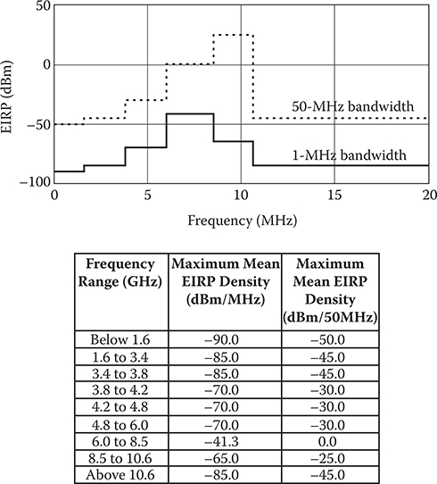
FIGURE 4.9
EU ECC-CEPT maximum UWB EIRP densities in the absence of appropriate mitigation techniques after December 31, 2010. (Adapted from Commission of the European Communities, Commission decision of 21 February 2007 on allowing the use of the radio spectrum for equipment using ultra-wideband technology in a harmonised manner in the Community, (notified under document number C(2007) 522), Official Journal of the European Union, March 23, 2007.)“automotive vehicle” means any vehicle as defined by Directive 70/156/EEC;
“railway vehicle” means any vehicle as defined by Regulation 91/2003;
“e.i.r.p.” means equivalent isotropic radiated power.
Figure 4.9 summarizes the ECC-CEPT Maximum UWBEIRP densities in the absence of appropriate mitigation.
4.3.3.2 EU Ground- and Wall-Probing Radar (GPR/WPR) Frequency Spectrum Allocations
The “Electronic Communications Committee (ECC) Decision of 1 December 2006 on the Conditions for Use of the Radio Spectrum by Ground- and Wall-Probing Radar (GPR/WPR) Imaging Systems,” Report ECC/DEC/(06)08 sets out restrictions for designers. The following extract contains the most relevant information [3].
Explanatory Memorandum
1. INTRODUCTION
UWB Ground- and Wall-Probing Radar (GPR/WPR) imaging systems have been used by professionals for over 30 years in several European countries in survey and detection applications. GPR/WPR imaging systems have a significant effect on every day life such as locating underground gas main leaks, locating dangerous sink-holes, finding survivors of avalanches, surveying roads at normal traffic speeds, etc., while noting that a number of the radio services operating in the frequency bands covered by GPR/WPR are used for aviation, meteorology, defence, etc.
The European Telecommunications Standards Institute (ETSI) has developed ETSI Technical Report TR 101 994-2 (Technical characteristics for SRD equipment using Ultra Wide Band Technology (UWB), Part 2; Ground- and Wall-Probing-Radar applications) and the corresponding Harmonized European Standard EN 302 066 for GPR/WPR Radar applications which includes the technical characteristics and test methods for such equipment. The scope of ETSI EN 302 066 is limited to radars operated as short range devices (because of their usage and design), in which the system is in close proximity to the materials being investigated. It does not include radars operated from aircraft or spacecraft. In addition, highly specialized equipment using the frequencies typically below 100 MHz may use higher output power for geophysical applications (e.g. hydro-geophysical surveys).
Annex 1
Technical requirements for the operation of GPR/WPR imaging systems
GPR and WPR imaging systems shall be designed to operate while in contact with, or in close proximity to the ground or the wall, and their emissions being directed into the ground or wall (e.g. measured by a proximity sensor or imposed by the mechanical design).
GPR/WPR equipment shall have a deactivation mechanism of the equipment which is a function to deactivate the equipment when normal use is interrupted. This mechanism shall fulfil the following requirements:
Manually operated GPR and WPR, which is intended to be used as handheld equipment, shall contain a manually operated non-locking switch (e.g., it may be a sensor for the presence of the operators hand or a movement sensor) which ensures that the equipment de-activates (i.e., the transmitter switches off) within 10 seconds of being released by the operator.
In the case of remotely/computer controlled imaging equipment, the equipment is de-activated via the control system provided that de-activation takes place within 10 seconds of the control system being switched off or released by the operator.
There are particular cases where the equipment is mounted in a vehicle for the collection of data where the deactivation time required is 60 seconds.
Maximum mean and peak power densities of any undesired emission emanating from GPR/WPR imaging systems are defined below. For pragmatic reasons and for taking the mitigation factors into account, the mean power density shall be determined by formula (1) or (2) below and the peak values shall be measured according to ETSI EN 302 066-1.
Note 1: GPR/WPRs operate across a wide range of spectrum where established radio services operate. These services have diverse bandwidths, some may be susceptible to peak signal levels and others to average signal levels. There are technical and practical issues, related to bandwidth, the effective loading of the GPR/WPRs radiation by earth materials and the limitations of instrumentation. It is acknowledged that peak signals levels will be measured and average signal levels calculated based upon the duty cycle of the GPR/WPR.
The mean power density of any undesired emission emanating from GPR/WPR imaging systems shall be kept to a minimum and not exceed the limits in Table 1 [Table 4.6] below.
The measured radiated power density of any undesired emission emanating from GPR/WPR imaging systems shall not exceed the limits as given in table 2 [Table 4.7] below
Figure 4.10 shows the maximum EIRP and undesired radiation limits for ground- and wall-penetrating radar systems determined by EU.
The time domain architecture of GPR/WPRs and patterns of use imply that there is wide variation in the total power emitted in any time period. For pulsed systems this includes the duration of pulses compared to the time between pulses, the time between bursts of pulses when the system is being moved to the next measurement position and other operational factors. This should be taken into account when considering the mean power that may be incident upon a vulnerable radio service. In order to accommodate all these factors a conversion factor is used to evaluate the mean power that should be compared to the limits in table 1 (Table 4.7). This conversion factor has been established as a simple and practical way to assess mean power levels based on the measurement of peak power levels.
TABLE 4.6
EU Mean Power Density Minimum from GPR/WPR Imaging Systems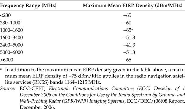
TABLE 4.7
EU GPR/WPR Imaging System Power Density Limits for Undesired RadiationFrequency Range (MHz) Maximum Peak Power 30-230 -44,5 dBm/120kHz (EIRP) > 230-1000 -37,5 dBm/120kHz (EIRP) > 1,000-18,000 -30 dBm/MHz (EIRP) The method of measurements for peak power values are given by EN 302 066-1 V1.1.1, part 8.2.2.
Source: ECC-CEPT, Electronic Communications Committee (ECC) Decision of 1 December 2006 on the Conditions for Use of the Radio Spectrum by Ground- and Wall-Probing Radar (GPR/WPR) Imaging Systems, ECC/DEC/(06)08 Report, December 2006.

FIGURE 4.10
EU ECC-CEPT GPR and WPR imaging systems mean power density minimum and undesired power density limits. (Adapted from ECC-CEPT, Electronic Communications Committee (ECC) Decision of 1 December 2006 on the Conditions for Use of the Radio Spectrum by Ground- and Wall-Probing Radar (GPR/WPR) Imaging Systems, ECC/DEC/(06)08 Report, December 2006)When determining mean power values, for pulsed systems, to be compared with the values in table 1 the following formula shall be used:
(1) Power mean = Power peak + conversion_factor with: conversion factor = 10 log (PRF × τ)
where
—τ is the pulse width of the GPR transmitter measured at the 50% amplitude points of the envelope at boresight with an UWB probe and a suitable oscilloscope. When performing this measurement, care should be taken that the pulse is properly gated, i.e. no reflectors should be allowed to influence the pulse while travelling from the GPR transmitter to the UWB probe. The UWB probe/antenna should have a bandwidth wide enough to capture the UWB signal from the GPR/WPR properly.
—PRF is the pulse repetition frequency.
For systems using step-frequency waveforms, the wideband signal is formed by transmitting a sequence of discrete frequencies each having a Dwell Time (DT). The length of the total sequence is referred to as the Scan Time (ST). The Scan Time is identical to the Cycle Time in frequency hopping systems, and it is the interval between each time the transmitter is hopping back to the first frequency in the sequence.
“For calculating the mean power value for a step-frequency system, the following formula shall be used:
(2) Power mean = Power peak + conversion factor with: conversion facto = 10 log (DT/ST) where
—“DT is measured at the 50% amplitude points of the envelope at boresight with an UWB probe and a spectrum analyser in zero-span mode at a frequency near the maximum of the radiated spectrum using 1MHz resolution bandwidth. ST is measured in the same way using a spectrum analyser in zero-span mode and 1MHz resolution bandwidth.
Appendix 1 to Annex 1
(Informative)
Measurement of τ, transmit pulse width.
There are two ways of measuring τ, time domain and frequency domain methods.
1. Time domain.
The GPR antenna is lifted off the ground and pointed directly towards the measurement antenna. The distance between the DUT (device under test) and receive antenna shall be greater than one wavelength (at the lowest frequency radiated). Care is taken so that there are no unwanted multipath reflections included in the time interval where the pulse width measurement is carried out. The non-dispersive antenna/UWB-probe should have a fractional bandwidth wide enough to represent the UWB, signal (GPR/WPR typically have a fractional bandwidth greater than 100%).
Figure 4.11 shows the test set up for time domain measurements of the pulse length and pulse repetition frequency for ground- and wall-probing radar.
2. Frequency domain.
The RF bandwidth of a single pulse modulated carrier is approximately = 1/τ. By measuring the occupied bandwidth an equivalent pulse width is calculated. There is no need to have a non-dispersive antenna or oscilloscope any more, the measurement is done with the same antenna and spectrum analyser as for the peak power measurement as per section 8.1 in EN302-066-01, but with the GPR and measurement antenna facing each other, see figure 2. (Figure 4.11)

FIGURE 4.11
EU test set up for time domain measurements of pulse length and pulse repetition frequency for ground-and wall-probing radar (GPR/WPR) imaging systems. (Adapted from ECC-CEPT, Electronic Communications Committee (ECC) Decision of 1 December 2006 on the Conditions for Use of the Radio Spectrum by Ground- and Wall-Probing Radar (GPR/WPR) Imaging Systems, ECC/DEC/(06)08 Report, December 2006.)

FIGURE 4.12
Frequency domain undesired radiation measurement from Figure 2 to Annex 1 “Electronic Communications Committee (ECC) Decision of 1 December 2006 on the conditions for use of the radio spectrum by ground-and wall-probing radar (GPR/WPR) imaging systems.” (Adapted from ECC-CEPT, Electronic Communications Committee (ECC) Decision of 1 December 2006 on the Conditions for Use of the Radio Spectrum by Ground- and Wall-Probing Radar (GPR/WPR) Imaging Systems, ECC/DEC/(06)08 Report, December 2006.)
To avoid multipath reflections distorting the measurement, this test is carried out in an open test area or in an anechoic room.
τ = 1/(Fupper - Flower), - 10 db measurement points.
Figure 4.12 shows the test set up for frequency domain measurements of the pulse duration t and pulse repetition frequency using a spectrum analyzer.
4.3.3.3 UWB Low Duty Cycle (LDC) Devices to Ensure the Protection of FWA Systems
Synopsis of ECC-CEPT, “Technical Requirements for UWB LDC Devices to Ensure the Protection of FWA (Fixed Wireless Access) SYSTEMS,” Nicosia, December 2006, ECC Report 94 [4].
This report defines the duty cycle condition for fixed and mobile UWB systems such as:
Monitoring systems for temperature, light level, water leakage, etc.
Pure home automation, e.g. remote control applications such as closing blinds or portals.
Real-time location- tracking, e.g. switching on the lights when a person enters the room, baby-monitoring with alarm when approaching “dangerous” areas.
Location-tracking, e.g., following objects in a production line, location of working- teams on an indoor industrial site, logistics management on an indoor industrial site
Industrial sensors
1. Introduction
Working under EC mandate, CEPT has studied and defined technical requirements for efficient mitigation techniques such as low duty cycle (LDC) in the 3.4 to 4.8GHz band. At November 2005 ECC TG3 meeting, a contribution submitted by one administration has shown some results based on measurements on efficacy of double-limitation (5% over one second, 0.5% over one hour) for UWB LDC to protect FWA and other systems. ECC TG3 requested however additional measurement campaigns to be performed.
This report has been developed by ECC TG3 for European Conference of Postal and Telecommunications Administrations (CEPT). Two campaigns of measurement have been performed to cover all issues raised by TG3 and dedicated correspondence group. This report presents the results of these measurements campaigns and concludes on technical requirements for UWB LDC devices to ensure the protection of FWA systems.
The technical requirements for UWB LDC devices and the associated new definition presented in this report are proposed to be integrated in the annex of a relevant ECC Deliverable.
2. Victim Services
The technical requirement is based on investigation on typical IEEE.802.16 WiMAX system only operating at 3.4 to 4.2 GHz band. Therefore other non IEEE 802.16 FWA systems and future possible mobile applications in bands from 3.4 up to 4.2/4.8 GHz should be further investigated.
The band 3.1-3.4 GHz is not considered in the scope of this analysis because it’s not allocated to FS or MS. Different constraints might apply to Radiolocation services operating in this band.
3. Definition of LDC and Proposed Parameter
Contributions have clarified the principles and concepts behind LDC set of regulations demonstrating the need to introduce limitations based on burst duration (Ton) and burst intervals (Toff).
ECC Dec (06)04 contains the definition of duty cycle as well as impulse, pulse and burst as reproduced below.
Duty cycle For the purpose of this Decision the duty cycle is defined as the ratio, expressed as a percentage, of the transmitter sum of all burst duration “on” relative to a given period as specified in the technical requirements.
Impulse, Pulse and Burst
Impulse: a surge of unidirectional polarity that is often used to excite a UWB band limiting filter whose output, when radiated, is a UWB pulse.
Pulse: a radiated short transient UWB signal whose time duration is nominally the reciprocal of its UWB -10 dB bandwidth.
Burst: an emitted signal whose time duration (Ton) is not related to its bandwidth
In line with the technical requirement for LDC, it is proposed to add the following new definition.
ΣTon: For the purpose of this Decision, the Ton is defined as the duration of a burst irrespective of the number of pulses contained.
ΣToff: For the purpose of this Decision the Toff is defined as the time interval between two consecutive bursts when the UWB emission is kept idle.
Based on conclusion of the measurement, the following LDC technical requirement is proposed (see Table 4.8).
4. UWB Requirements and Application [4]
From UWB point of view, LDC restricts the UWB operation mostly to low duty cycle (LDC) applications, although short time communications type of operation is also possible. Concerns were expressed that LDC applications could be predominantly communications and could be located very close to victim terminals. However, it was indicated that some LDC application such as M2M applications (monitoring sensors, object/person location tracking devices either for home automation or industrial/working sites) would not be generally located in close proximity to victim terminals.
TABLE 4.8
EU Limits for LDC Systems
|
Ton max = 5 ms Toff mean > 38 ms (averaged over 1 s) ⊠ Toff > 950 ms/s ⊠ Ton <5%/s; and 0.5%/h; PSD max, -1.3 dBm/MHz |
Source: ECC-CEPT, Technical Requirements for UWB LDC Devices to Ensure the Protection of FWA (Fixed Wireless Access) Systems, ECC Report 94, Nicosia, Italy, December 2006.
As a result of discussions in the IEEE 802.15.4a group, it appears that some targeted UWB applications, such as accurate ranging, instantaneously need some minimum Ton and a very short Toff. This is further explained in Annex 1.
4.1 Applications for UWB LDC
UWB applications are mainly foreseen to be focused on sensor network in home, office or industrial environment. Compared to existing wireless technologies already addressing this market (like IEEE 802.15.4-2003-ZigBee), the main added value is the support for accurate indoor geolocalisation.
The following table is an attempt to give some usage applications of UWB-LDC with a view of evaluating the associated duty cycles and activity factors.
UWB LDC equipments can be split into two categories (Table 4.9):
![]() Fixed nodes: A very limited number of nodes in a sensor network will be “Anchor” to serve as a reference for geo-localisation and “Access point” for collecting data and coordinating the network. As those nodes will probably be wall mounted and fixed (an anchor is a reference for localisation and so can not be moved in the room), it is very unlikely that such a transceiver will get close (< 1 m) of a laptop computer, PDA or other FWA enabled devices.
Fixed nodes: A very limited number of nodes in a sensor network will be “Anchor” to serve as a reference for geo-localisation and “Access point” for collecting data and coordinating the network. As those nodes will probably be wall mounted and fixed (an anchor is a reference for localisation and so can not be moved in the room), it is very unlikely that such a transceiver will get close (< 1 m) of a laptop computer, PDA or other FWA enabled devices.
![]() Mobile nodes: They are tags attached to an asset, person or system to be tracked or monitored. Those transceivers are self-powered and must keep their activity as low as possible in order to maximise battery life.
Mobile nodes: They are tags attached to an asset, person or system to be tracked or monitored. Those transceivers are self-powered and must keep their activity as low as possible in order to maximise battery life.
Editor’s Note: The remainder of this document prescribes methods for measuring low duty cycle (LDC) characteristics such as Ton and Toff. Readers who require this type of information should refer to the original reference available online.
4.3.3.4 EU Requirements for Object Discrimination and Characterization of Devices
Extract of ECC-CEPT, “The Impact of Object Discrimination and Characterization (ODC) Applications Using Ultra-Wideband (UWB) Technology on Radio Services,” ECC Report 123, Vilnius, September 2008 [9]:
TABLE 4.9
EU LDC UWB Applications Duty Cycle and Activity Factor Limitations
| Domain | Application | Duty Cycle (δ) | Activity Factor (AF) | Comments/Other Elements |
| Home/Office | Monitoring sensors (for temperature, luminosity, detection of water leak from a machine, warning for plants watering, and so on) | Transmission of data only when the monitored event occurs at +1 ms/min in any case for showing up | Activity linked to an event 3 very low activity factor (≪0.1%) | Need for a home-automation gateway and sensors on the objects |
| Pure home automation, i.e., remote control applications such as closing blinds or a portal when detection of corresponding parameters occurs | Transmission of data only when the monitored event occurs at +1ms/minin any case for showing up | Activity linked to an event 3 very low activity factor (≪0.1%) | Need for a home-automation gateway and sensors on the objects or persons | |
| Real-time location-tracking -Switching on the lights when a person enters the room -Baby-monitoring with alarm when approaching “dangerous” areas | For example, baby-monitoring: location-sensing twice/second, 2 ms/evaluation = 4 ms/s 3δ = 0.4% | For baby-monitoring, for example, no more than 6 h/day; AF = 0.25 × 0.004 = 0.1% | Fixed beacons around the rooms where the baby can go, predetermination of areas considered dangerous | |
| Industrial | Location-tracking -Follow-up of objects in a production line -Location of working-teams on an industrial site (indoor) to contact the nearest one in case of urgent action required -Logistics management on an industrial site (indoor) | For example, follow-up of objects in a production-line: regular transmissions of dynamic information from the object (status, location) 2 ms-transmissions/second 3,5 = 0.2% | 10 h/day, AF = 0.4 × 0.002 = 0.08% | |
| Industrial sensors | Short-data transmissions in the order of lms/second 3δ = 0.1% | 24 h/day for a nonstop production factory, AF = 1 × 0.001 = 0.1% |
Source: ECC-CEPT, Technical Requirements for UWB LDC Devices to Ensure the Protection of FWA (Fixed Wireless Access) Systems, ECC Report 94, Nicosia, Italy, December 2006.
Executive Summary
Although some ECC decisions address already specific UWB applications for imaging and probing applications ([1] and as well as generic UWB applications ([3] and [4]), this report considers an additional request from ETSI on Object Discrimination and Characterization (ODC) published in [5]. This report considers the possible impact of ODC on radio services/systems taking into account existing regulation for UWB by defining a spectrum emission mask, based on assumptions for the density and activity factor applicable for Europe. Details are given in the referred sections of the report.
As a result of these studies the limits of existing UWB regulations are applicable to ODC in some bands: below 1.73 GHz: the limits of ECC/DEC/(07)01 [2] are applicable to ODC, but not considering the LBT option from 2.2 to 2.5 GHz, 3.8 to 4.8 GHz, 5 to 5.25 GHz, 5.35 to 5.6 GHz and 5.725 to 8.5 GHz: the limits of ECC/DEC/(07)01 [2] are applicable to ODC above 8.5 GHz: the limits of ECC/DEC/(06)04 [3] are applicable to ODC. Deviations from existing UWB regulations are needed in the other bands and these requirements are summarized in Table 4.10.
4.3.3.5 EU Restrictions for Material Sensing Devices
Extract of the “ECC Decision of 30 March 2007 on Specific Material Sensing Devices Using Ultra-Wideband (UWB) Technology, Report ECC/DEC/(07)01, Amended 26 June 2009”[10]
Explanatory Memorandum
1. Introduction
This ECC Decision has been developed in response to market demands for Building Material Analysis (BMA) and Object Discrimination and Characterisation (ODC) devices using UWB technology devices. The ECC Decision should ensure that frequency bands are available on a harmonised basis to enable the introduction of UWB devices in a timely manner and ensuring economies of scale while ensuring protection of existing applications or services. It should be noted that this ECC Decision is designed to be part of a “regulatory package” on UWB, with various regulatory and legal provisions. The generic regulation for UWB devices in Europe consists of Decision ECC/DEC/(06)04 supplemented by Decision ECC/DEC/(06)12 and was developed to respond primarily to the core market demand for communication applications and cable replacement. It enables also various types of radiodetermination applications using UWB technology in bands below 10.6 GHz e.g. location-tracking, sensor technologies. In addition, Decision ECC/DEC/(06)08 on the conditions for use of the radio spectrum by Ground-and Wall- Probing Radar (GPR/WPR) imaging systems was developed to respond to a specific UWB requirement that shall be subject to an appropriate licensing regime.
2. Background
In response to demands brought to the attention of ECC by industry, harmonised frequency bands are required for the introduction of BMA and ODC devices ensuring economies of scale and a harmonised introduction of these devices inside CEPT.
BMA devices can be described as field perturbation sensors, or radiodetermination systems, that are designed to detect the location of objects within a building structure or to determine the physical properties of a building material.
In the case of ODC devices, two types of applications were distinguished in the compatibility studies:
—Application A: Proximity Sensing of Human tissue
—Application B: “Break through” protection and direct contact avoidance for building work
Application A is intended for:
—detection of small objects like a finger or other extremities in the presence of obstacles (e.g. wood), positioned close to a hazard like a saw blade;
—applications typically for consumer market, like safety devices for power tools or dangerous machines;
—usage in close proximity to potentially hazard area (0 to 40 cm).
TABLE 4.10
Summary of Deviations from Existing UWB Regulations
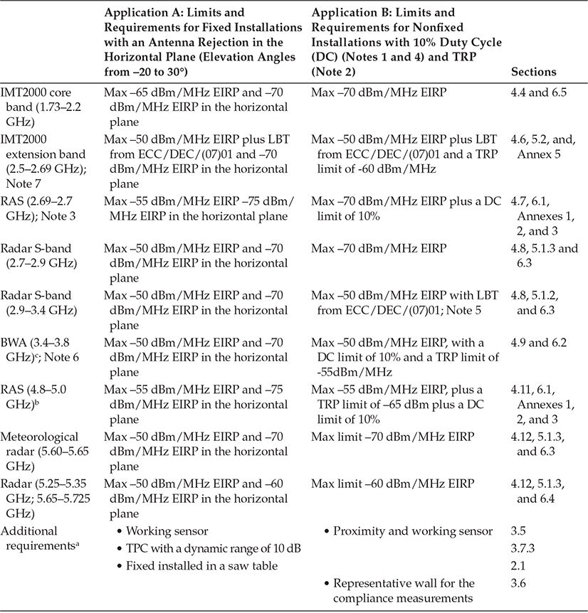

Application B will be used for high end drilling and percussion drilling machines. It is planned to mount it directly to the tool. A parallel usage is possible. The UWB sensor application monitors the drilling process and controls the drilling machine also depending on the inhomogenities in the material. The user will be warned acoustically or optically in case of a collision with unexpected objects inside the material (e.g. gas-water pipes or electric cables) may happen. The UWB application may be active synchronously to the operation of the drilling machine which will be supported by this application.
The detailed compatibility studies performed by CEPT considered the specific deployment scenarios and mitigation factors of BMA or ODC and have led to highly specific requirements in different frequency bands, taking into account specificities of the victim services and operational requirements for BMA or ODC.
Comparable technical specifications to those in this ECC Decision are given in EC Decision 2009/343/EC. EU member states and, if so approved by the EEA Joint Committee, Iceland, Liechtenstein and Norway are obliged to implement the EC Decision.
The European Conference of Postal and Telecommunications Administrations, considering
That Commission decision 2007/131/EC on allowing the use of the radio spectrum for equipment using ultrawideband technology in a harmonised manner in the Community amended by Commission decision 2009/343/EC of 21 April 2009 defines conditions of use of the spectrum for BMA devices;
that Ultra-Wideband (UWB) technology shall mean technology for short-range radiocommunication, involving the intentional generation and transmission of radio-frequency energy that spreads over a very large frequency range, which may overlap several frequency bands allocated to radiocommunication services;
that the generic UWB regulation consisting of Decision ECC/DEC/(06)04 supplemented by Decision ECC/DEC/(06)12 should primarily be used for applications using UWB technology in bands below 10.6 GHz;
that, in order to allow the introduction of Building Material Analysis (BMA) and Object Discrimination and Characterisation (ODC) devices using UWB technology within the CEPT, the use of the frequency range 2.2 to 8.5 GHz has been requested by the industry because:
—there is a need for higher emission limits than those contained in Decision ECC/DEC/(06)04 in certain frequency ranges,
—a larger bandwidth is required for spatial resolution,
—lower frequency bands are required for material penetration and clutter suppression,
—the technology is available;
that the radiated emissions of BMA and ODC devices are intended to be transmitted into a structure or material for the purpose of detecting the location of objects within the structure or to determine the physical properties of the material;
that a regulatory framework for specific licence-exempt material sensing devices using UWB technology will enable the operation of BMA and ODC devices as well as other types of radiodetermination applications with similar characteristics;
that the impact of ODC on radio communication services has been investigated in ECC Report 123, making a distinction between ODC application A (Proximity Sensing of Human tissue) and application B (“Break through” protection and direct contact avoidance for building work) and subsequent corresponding technical requirements;
that the density and activity of operation of these devices is expected to be low;
—for BMA within the technical studies a maximum density of 6.7 units/km2 for very dense urban areas with an average activity factor of 0.28% was considered;
—for ODC within the technical studies a maximum density of 19 units/km2 for dense urban areas with an average activity factor of max 3% was considered
that these BMA and ODC devices are not intended for communications purposes;
that the consideration of the specific deployment scenarios and mitigation factors of BMA or ODC has led to specific requirements in different frequency bands, taking into account also specificities of the victim services and operational requirements for BMA or ODC compared to the generic regulation for UWB;
that BMA and ODC devices have to reduce the probability of interference to radio services by mitigation techniques and factors such as
—manually controlled operation without a locking switch,
—emissions only when in contact or close proximity to the investigated material,
—movement detector,
—handheld devices using internal battery power source,
—low duty cycle,
—Listen Before Talk (LBT), Total Radiated Power (TRP) limitation, “Transmit Power Control (TPC)
— Antenna Pattern design;
that technical requirements for LBT mechanisms given in this ECC Decision need to be supplemented by adequate guidance on LBT measurement procedures and test patterns as defined in relevant standards (e.g. relevant versions of EN 302 435 and EN 302 498-2 including Harmonised European Standards adopted under Directive 1999/5/EC);
that the LBT mechanism for BMA devices may not be fully efficient to detect meteorological radars in some of their specific operational modes but that, recognising the low activity factor of BMA, potential corresponding interference situations are assumed as relating to very low interference probability;
that the efficiency of LBT may need to be further investigated for the protection of mobile terminals in idle mode;
that the aggregate power in radio astronomy receivers that would result from the operation of licence-exempt BMA and ODC devices in bands allocated to the Radio Astronomy Service may exceed the threshold levels of interference detrimental to radio astronomy observations given in ITU-R Recommendation RA.769;
that administrations are encouraged to monitor the impact of BMA and ODC devices on radiocommunication services, especially on RAS;
that based on the experience gained, a review of this Decision should take place in 2010, consider in priority the technical requirements for BMA devices which were originally agreed in 2007, and if necessary further measures could be introduced like automatic deactivation, light licensing or more stringent limits;
that in EU/EFTA countries the radio equipment that is under the scope of this Decision shall comply with the R&TTE Directive. Conformity with the essential requirements of the R&TTE Directive may be demonstrated by compliance with the applicable harmonised European standard(s) or by using the other conformity assessment procedures set out in the R&TTE Directive;
Decides
that this ECC Decision defines harmonised conditions for the use in CEPT countries of Material Sensing devices using UWB technology;
that, for the purpose of this Decision, the following definitions apply:
Material Sensing device: a device enabling radiodetermination application designed to detect the location of objects within a structure or to determine the physical properties of a material.
Building Material Analysis (BMA) device: a type of Material Sensing device that is designed to detect the location of objects within a building structure or to determine the physical properties of a building material;
that the devices permitted under this ECC Decision are exempt from individual licensing and shall operate on a non-interference, non-protected basis;
that the technical requirements detailed in Annex 1 and Annex 3 apply to Material Sensing device devices permitted under this ECC Decision;
that the technical requirements detailed in Annex 2 and Annex 3 apply to BMA devices permitted under this ECC Decision;
that this Decision enters into force on 26 June 2009;
that the preferred date for implementation of this Decision shall be 31 December 2009;
that CEPT administrations shall communicate the national measures implementing this Decision to the ECC Chairman and the Office when the Decision is nationally implemented.”
Note:
Please check the Office web site (http://www.ero.dk) for the up to date position on the implementation of this and other ECC decisions.
Annex 1
Technical requirements for Material Sensing devices using UWB technology
Material Sensing devices permitted under this Decision shall fulfil the following requirements:
—Fixed installation (application A)
—The transmitter has to switch off if the machine is not running, “running sensor”
—The transmitter shall implement a TPC with a dynamic range of 10 dB, as described in the harmonised standard EN 302 498-2 for ODC applications
—The transmitter has to be attached to a fixed installation —Non fixed installation (application B)
—Transmitter-On only if manually operated with a non-locking switch (e.g. it may be a sensor for the presence of the operators hand) plus being in contact or close proximity to the investigated material and the emissions being directed into the direction of the object (e.g. measured by a proximity sensor or imposed by the mechanical design)
—The transmitter has to switch off if the machine is not running, “running sensor”
Emissions radiating from Material Sensing devices permitted under this decision shall be kept to a minimum and in any case not exceed the e.i.r.p. spectral density limits within the following Table 1 [Table 4.11.] The compliance with the limits of Table 1 [Table 4.11] for non fixed installations (application B) has to be ensured with the device on a representative structure of the investigated material (e.g. representative wall as defined in Annex 3).”
Table 4.11 shows the technical requirements for material sensing devices using UWB technology. Figure 4.13 shows the EU requirements shown in Table 4.9.
Amended ECC/DEC/(07)01
Technical requirements of the “Listen Before Talk” mechanism for Material Sensing devices
Peak power threshold value for the “Listen Before Talk” (LBT) mechanism to ensure the protection of the listed services are defined within Table 2 [Table 4.12] below.
Technical requirements of the “Listen Before Talk” mechanism for Material Sensing devices (10)
Additional requirements for Radar detection: Continuously listening and automatic switch-off within 10 ms for the related frequency range if the threshold value is exceeded (Table 4.12). A silent time of at least 12 s while listening continuously is necessary before the transmitter can be switched on again. This silent time during which only the LBT receiver is active has to be ensured even after the device is switched off by the functions described in Annex 1, the proximity sensor and manual operation.
4.3.3.6 Supplementary Regulations for UWB Devices Using Mitigation Techniques
Extracts of ECC “Decision of 1 December 2006 amended Cordoba, 31 October 2008 on supplementary regulatory provisions to Decision ECC/DEC/(06)04 for UWB devices using mitigation techniques” (ECC/DEC/(06)12) amended 31 October 2008 [7].
4.3.3.6.1 Regulations for LDC Devices
1. Introduction
This ECC Decision has been developed in response to an EC mandate to CEPT to identify the conditions relating to the harmonised introduction in the European Union of radio applications based on ultra-wideband (UWB) technology. CEPT was mandated to undertake all the necessary work to identify the most appropriate criteria for the timely and harmonised introduction of UWB applications in the European Union. This ECC Decision supplements Decision ECC/DEC/(06)04 amended 6 July 2007 on the harmonised conditions for devices using UWB technology in bands below 10.6 GHz and defines conditions of use applicable to UWB devices implementing Low Duty Cycle (LDC) or Detect And Avoid (DAA) mitigation techniques.
TABLE 4.11
EU Technical Requirements for Material Sensing Devices Using UWB Technology

2. Background
The frequency band 6-8.5 GHz has been identified in Europe for long-term UWB operation with a maximum mean e.i.r.p. spectral density of -41.3 dBm/MHz and a maximum peak e.i.r.p. of 0 dBm measured in a 50MHz bandwidth without the requirement for additional mitigation.
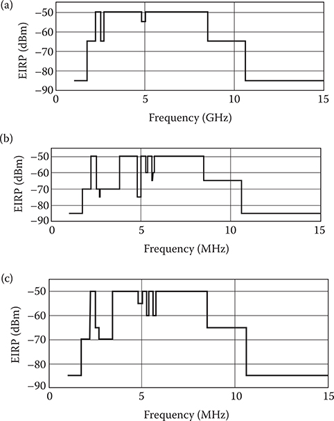
FIGURE 4.13
EU requirements for UWB material sensing devices. Maximum EIRP spectral density for (a) fixed installations, (b) fixed installations in the horizontal place (-20°,-30° elevation), and (c) nonfixed installations (see Table 4.11 for exact frequencies). (Adapted from ECC, ECC Decision of 30 March 2007 on Specific Material Sensing Devices Using Ultra-Wideband (UWB) Technology, Report ECC/DEC/(07)01, amended June 26, 2009.)
TABLE 4.12
EU “Appendix 1 Table 2: Technical Requirements of the ‘Listen Before Talk’ Mechanism for Material Sensing Devices”
| Frequency Range (GHz) | Radio Service to Be Detected | Peak Power Threshold Value (dBm/MHz) |
| 2.5-2.69 | Land mobile service | -50 |
| 2.9-3.4 | Radio determination service | -7 |
Source: ECC, ECC Decision of 30 March 2007 on Specific Material Sensing Devices Using Ultra-Wideband (UWB) Technology, Report ECC/DEC/(07)01, amended June 26, 2009.
In the frequency band 3.1-4.8 GHz and 8.5-9 GHz, ECC has investigated DAA (Detect And Avoid) and LDC (Low Duty Cycle) mitigation techniques in order to ensure the protection of BWA terminals and applications in the radiolocation services, with a view of allowing UWB devices in the band 3.1-4.8 GHz and 8.5-9 GHz with maximum mean e.i.r.p. spectral density of -41.3 dBm/MHz.
Particular attention was paid to Detect and Avoid (DAA) mechanisms, which detect the presence of signals from other radio systems (such as fixed broadband wireless access and mobile services) and reduce the transmitted power of the UWB device down to a level where it does not cause interference to indoor reception of these systems.
ECC Reports 94 and 120 developed in support of this Decision do not address the protection of outdoor stations of radio services such as FS and FSS in the bands 3.4-4.2 GHz and 4.5-4.8 GHz. Complementary technical studies presented in CEPT Report 9 (using different propagation models and assuming 100% of UWB devices operating indoor with an average 1% activity factor) in support of Decision ECC/DEC/(06)04 provide some level of confidence regarding their protection from UWB devices transmitting with a maximum mean e.i.r.p. spectral density of -41.3 dBm/MHz. However, as the strict prohibition of outdoor use cannot effectively be enforced in case of mobile or portable license-exempt devices, this regulation includes provisions aiming to minimise UWB being used outdoor. During the development of this Decision, some countries underlined that they consider possible deployment in the future of passive radars operating in the band 8.5-9 GHz and that the effectiveness of DAA to protect these systems has not been studied on supplementary regulatory provisions to Decision ECC/DEC/(06)04 for UWB devices using mitigation techniques
The European Conference of Postal and Telecommunications Administrations, considering
Decision ECC/DEC/(06)04 amended 6 July 2007 on the harmonised conditions for devices using UWB technology in bands below 10.6 GHz;
that the frequency range below 4.8 GHz has advantages for UWB, because of the lower path loss compared to the range above 6 GHz and the near term availability of technology;
that UWB devices implementing mitigation techniques can be allowed to transmit at higher power than defined in Decision ECC/DEC(06)04 on the condition that these mitigation techniques provide at least an equivalent protection to those specified in ECC/DEC(06)04;
that limitations on the duty cycle of UWB devices and the implementation of Detect and Avoid (DAA) mechanism can improve the coexistence with other radiocommunication systems;
that technical requirements for LDC UWB devices to protect FWA terminals are presented in ECC Report 94;
that based on studies and measurement campaigns on the impact of LDC UWB devices on military radars in the band 3.1-3.4 GHz, it was concluded that the probability of a single LDC UWB device to radiate into the main beam of the radar is low and hence the risk of interference is negligible;
that technical requirements for DAA UWB devices to ensure the protection of radiolocation services in the bands 3.1-3.4 GHz and 8.5-9 GHz and BWA terminals in the band 3.4-4.2 GHz are presented in ECC report 120;
that DAA technical requirements in the band 8.5-9 GHz are based on characteristics of monostatic radiolocation systems and may be revised subject to reported risk of interference to other classes of X band radars considered to be deployed in the future, in particular passive radars;
that DAA technical requirements given in Annex 2 of this ECC decision need to be supplemented by adequate guidance on DAA measurement procedures and test patterns as defined in relevant standards (e.g. relevant versions of ETSI EN 302 065 including Harmonised European Standards adopted under Directive 1999/5/EC);
that DAA technical requirements should safeguard the protection of BWA terminal stations for more than 99.75% of the time; k) that DAA technical requirements will need to be reviewed as existing systems are subject to technological change and other systems may be deployed or developed in the future;
that the band 3.4-3.6 GHz was identified for IMT applications at WRC-07;
that the requirement of UWB DAA devices operating in the band 3.1-4.8 GHz to be capable of selecting an operating channel anywhere within the band 3.1–4.8 GHz band will provide additional mitigation to radio services operating in this band;
that UWB DAA devices are expected to operate predominantly indoors with an average 1% activity factor;
(o) that the exclusion of fixed outdoor stations from the scope of this Decision will also limit the operation of mobile outdoor devices;
Decides
that this ECC Decision defines supplementary regulatory provisions to Decision ECC/DEC/(06)04 for UWB devices using mitigation techniques;
that, for the purpose of the Decision, the following definitions apply:
LDC UWB devices are defined as devices using UWB technology that meet the technical requirements for Low Duty Cycle (LDC) mitigation technique given in Annex 1 of this Decision;
DAA UWB devices are defined as devices using UWB technology that meet the technical requirements for Detect And Avoid (DAA) mitigation technique given in Annex 2 of this Decision;
that the devices permitted under this ECC Decision are exempt from individual licensing and operate on a non-interference, non-protected basis;
that this ECC Decision is not applicable to:
devices and infrastructure installed at a fixed outdoor location or devices connected to a fixed outdoor antenna;
devices installed in flying models, aircraft and other aviation;
that for devices permitted under this ECC Decision, the technical requirements detailed in Annex 1 of Decision ECC/DEC/(06)04 apply, and, alternatively:
(a) within the band 3.1-4.8 GHz, LDC UWB devices are permitted to operate with a maximum mean e.i.r.p. spectral density of -41.3 dBm/MHz and a maximum peak e.i.r.p. of 0 dBm measured in 50MHz; notwithstanding that i. in case of LDC UWB devices installed in road and rail vehicles, no additional mitigation is required as the LDC mitigation technique is recognised to offer a protection level that is at least equivalent to Transmit Power Control (TPC);
(b) within the bands 3.1-4.8 GHz and 8.5-9 GHz, DAA UWB devices are permitted to operate with a maximum mean e.i.r.p. spectral density of -41.3 dBm/MHz and a maximum peak e.i.r.p. of 0 dBm measured in 50MHz; notwithstanding that,
(i) in case of DAA UWB devices installed in road and rail vehicles, operation is subject to the implementation of Transmit Power Control (TPC) with a range of 12 dB with respect to the maximum permitted radiated power. If no TPC is implemented, the maximum mean e.i.r.p. spectral density is -53.3 dBm/MHz;
that this Decision enters into force on 31 October 2008;
that the preferred date for implementation of this Decision shall be 1 May 2009;
that CEPT administrations shall communicate the national measures implementing this Decision to the ECC Chairman and the Office when the Decision is nationally implemented.”
Note: Please check the Office web site (http//:www.ero.dk) for the up to date position on the implementation of this and other ECC Decisions. Amended ECC/DEC/(06)12.
Table 4.13 summarizes the requirements for LDC mitigation techniques.
TABLE 4.13
EU Technical Requirements for LDC Mitigation Technique
Ton max = 5 ms ΣToff mean ≥ 38 ms (averaged over 1 s) ΣToff > 950 ms/s ΣTon < 18 s/h Ton is defined as the duration of a burst irrespective of the number of pulses contained Toff is defined as the time interval between two consecutive bursts when the UWB emission is kept idle Limit definition: The mean EIRP spectral density and peak EIRP power limits are defined during Ton |
Source: ECC, Decision of 1 December 2006 amended Cordoba, 31 October 2008 on supplementary regulatory provisions to Decision ECC/DEC/(06)04 for UWB devices using mitigation techniques Report ECC/DEC/(06)12, amended October 31, 2008.
4.3.3.6.2 Regulations for Detect and Avoid (DAA) Mitigation Techniques
Annex 2
(The content of this annex is meant to be respected by ETSI in the development of harmonised standards.)
Technical requirements for Detect And Avoid (DAA) mitigation technique
The flexible DAA proposal is based on the definition of different zones for which an appropriate UWB emission power level (maximum mean e.i.r.p. spectral density) is authorised. A zone is defined by a range of isolation between a device/system of a victim radio service and the UWB device. Theses zones and associated range of isolation correspond to the maximum mean e.i.r.p. spectral density levels specified in Table 1. (Table 4.13)
In the first zone, the UWB device shall operate at an emission level applied in the avoidance bandwidth as defined in table 1 (Table 4.13). In the last zone, the UWB device can operate without restriction up to the maximum permitted power level of -41.3 dBm/MHz or as defined in a future DAA regulation for the corresponding operational frequency range except in road and rail vehicles where additional restrictions apply. Between these extreme zones, a transition zone is defined for the band 3.4-4.8 GHz.
Before initiating UWB communications, the UWB device shall perform a monitoring of the RF environment during a minimum time to detect any actively operating victim signal (minimum initial channel availability check time value given in Table 1 [see Table 4.14]). Based on the result of this detection process, the UWB device has to determine the corresponding zone it occupies and react accordingly.
This function shall be able to detect victim systems signals and measure if this power level in a given bandwidth is above or below a detection threshold in any of the frequency bands denoted here after. This detection threshold is specified at the antenna connector assuming a 0 dBi antenna gain for each detection operation and may be based on multiple levels. This detection threshold can alternatively be expressed as a field strength limit.
The DAA UWB devices shall be able to continuously detect any change of the RF configuration (e.g. modification of operating zone) and switch to corresponding emission level within a maximum detect and avoid time according to the victim service and procedural tests Harmonized European defined in relevant standards (e.g. relevant versions of ETSI EN 302 065, including Harmonised European Standards adopted under Directive 1999/5/EC).
TABLE 4.14
EU Technical Parameters to Be Used by UWB DAA Devices
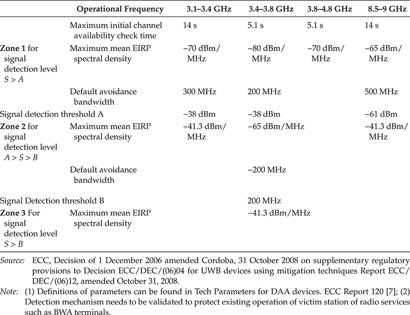
Table 4.14 summarizes the technical parameters of EU UWB DAA devices described in Section 4.3.3.6.2.
4.3.3.7 EU Requirements for LCD and DAA Devices below 10.6 GHz
Extract of ECC, “Decision of 1 December 2006 amended Cordoba, 31 October 2008 on supplementary regulatory provisions to Decision ECC/DEC/(06)04 for UWB devices using mitigation techniques” Report ECC/DEC/(06)12 amended 31 October 2008. [7]
4.3.3.7.1 EU Requirements for LCD Devices below 10.6 GHz
1. Introduction
This ECC Decision has been developed in response to an EC mandate to CEPT to identify the conditions relating to the harmonised introduction in the European Union of radio applications based on ultra-wideband (UWB) technology. CEPT was mandated to undertake all the necessary work to identify the most appropriate criteria for the timely and harmonised introduction of UWB applications in the European Union.
This ECC Decision supplements Decision ECC/DEC/(06)04 amended 6 July 2007 on the harmonised conditions for devices using UWB technology in bands below 10.6 GHz and defines conditions of use applicable to UWB devices implementing Low Duty Cycle (LDC) or Detect And Avoid (DAA) mitigation techniques.
2. Background
The frequency band 6-8.5 GHz has been identified in Europe for long-term UWB operation with a maximum mean e.i.r.p. spectral density of -41.3 dBm/MHz and a maximum peak e.i.r.p. of 0 dBm measured in a 50MHz bandwidth without the requirement for additional mitigation.
In the frequency band 3.1-4.8 GHz and 8.5-9 GHz, ECC has investigated DAA (Detect And Avoid) and LDC (Low Duty Cycle) mitigation techniques in order to ensure the protection of BWA terminals and applications in the radiolocation services, with a view of allowing UWB devices in the band 3.1-4.8 GHz and 8.5-9 GHz with maximum mean e.i.r.p. spectral density of -41.3 dBm/MHz.
Particular attention was paid to Detect and Avoid (DAA) mechanisms, which detect the presence of signals from other radio systems (such as fixed broadband wireless access and mobile services) and reduce the transmitted power of the UWB device down to a level where it does not cause interference to indoor reception of these systems.
ECC Reports 94 and 120 developed in support of this Decision do not address the protection of outdoor stations of radio services such as FS and FSS in the bands 3.4-4.2 GHz and 4.5-4.8 GHz. Complementary technical studies presented in CEPT Report 9 (using different propagation models and assuming 100% of UWB devices operating indoor with an average 1% activity factor) in support of Decision ECC/DEC/(06)04 provide some level of confidence regarding their protection from UWB devices transmitting with a maximum mean e.i.r.p. spectral density of -41.3 dBm/MHz. However, as the strict prohibition of outdoor use cannot effectively be enforced in case of mobile or portable license-exempt devices, this regulation includes provisions aiming to minimise UWB being used outdoor. During the development of this Decision, some countries underlined that they consider possible deployment in the future of passive radars operating in the band 8.5-9 GHz and that the effectiveness of DAA to protect these systems has not been studied on supplementary regulatory provisions to Decision ECC/DEC/(06)04 for UWB devices using mitigation techniques
(ECC/DEC/(06)12) amended 31 October 2008
The European Conference of Postal and Telecommunications Administrations, considering
Decision ECC/DEC/(06)04 amended 6 July 2007 on the harmonised conditions for devices using UWB technology in bands below 10.6 GHz;
that the frequency range below 4.8 GHz has advantages for UWB, because of the lower path loss compared to the range above 6 GHz and the near term availability of technology;
that UWB devices implementing mitigation techniques can be allowed to transmit at higher power than defined in Decision ECC/DEC(06)04 on the condition that these mitigation techniques provide at least an equivalent protection to those specified in ECC/DEC(06)04;
that limitations on the duty cycle of UWB devices and the implementation of Detect and Avoid (DAA) mechanism can improve the coexistence with other radiocommunication systems;
that technical requirements for LDC UWB devices to protect FWA terminals are presented in ECC Report 94;
that based on studies and measurement campaigns on the impact of LDC UWB devices on military radars in the band 3.1-3.4 GHz, it was concluded that the probability of a single LDC UWB device to radiate into the main beam of the radar is low and hence the risk of interference is negligible;
that technical requirements for DAA UWB devices to ensure the protection of radiolocation services in the bands 3.1-3.4 GHz and 8.5-9 GHz and BWA terminals in the band 3.4-4.2 GHz are presented in ECC report 120;
that DAA technical requirements in the band 8.5-9 GHz are based on characteristics of monostatic radiolocation systems and may be revised subject to reported risk of interference to other classes of Xband radars considered to be deployed in the future, in particular passive radars;
that DAA technical requirements given in Annex 2 of this ECC decision need to be supplemented by adequate guidance on DAA measurement procedures and test patterns as defined in relevant standards (e.g. relevant versions of ETSI EN 302 065 including Harmonised European Standards adopted under Directive 1999/5/EC);
that DAA technical requirements should safeguard the protection of BWA terminal stations for more than 99.75% of the time;
that DAA technical requirements will need to be reviewed as existing systems are subject to technological change and other systems may be deployed or developed in the future;
that the band 3.4-3.6 GHz was identified for IMT applications at WRC-07;
that the requirement of UWB DAA devices operating in the band 3.1-4.8 GHz to be capable of selecting an operating channel anywhere within the band 3.1-4.8 GHz band will provide additional mitigation to radio services operating in this band;
that UWB DAA devices are expected to operate predominantly indoors with an average 1% activity factor;
that the exclusion of fixed outdoor stations from the scope of this Decision will also limit the operation of mobile outdoor devices;
Decides
that this ECC Decision defines supplementary regulatory provisions to Decision ECC/DEC/(06)04 for UWB devices using mitigation techniques;
that, for the purpose of the Decision, the following definitions apply:
LDC UWB devices are defined as devices using UWB technology that meet the technical requirements for Low Duty Cycle (LDC) mitigation technique given in Annex 1 of this Decision;
DAA UWB devices are defined as devices using UWB technology that meet the technical requirements for Detect And Avoid (DAA) mitigation technique given in Annex 2 of this Decision;
that the devices permitted under this ECC Decision are exempt from individual licensing and operate on a non-interference, non-protected basis;
that this ECC Decision is not applicable to:
devices and infrastructure installed at a fixed outdoor location or devices connected to a fixed outdoor antenna;
devices installed in flying models, aircraft and other aviation;
that for devices permitted under this ECC Decision, the technical requirements detailed in Annex 1 of Decision ECC/DEC/(06)04 apply, and, alternatively:
(a) within the band 3.1-4.8 GHz, LDC UWB devices are permitted to operate with a maximum mean e.i.r.p. spectral density of -41.3 dBm/MHz and a maximum peak e.i.r.p. of 0 dBm measured in 50MHz; notwithstanding that i. in case of LDC UWB devices installed in road and rail vehicles, no additional mitigation is required as the LDC mitigation technique is recognised to offer a protection level that is at least equivalent to Transmit Power Control (TPC);
(b) within the bands 3.1-4.8 GHz and 8.5-9 GHz, DAA UWB devices are permitted to operate with a maximum mean e.i.r.p. spectral density of -41.3 dBm/MHz and a maximum peak e.i.r.p. of 0 dBm measured in 50MHz; notwithstanding that,
(i) in case of DAA UWB devices installed in road and rail vehicles, operation is subject to the implementation of Transmit Power Control (TPC) with a range of 12 dB with respect to the maximum permitted radiated power. If no TPC is implemented, the maximum mean e.i.r.p. spectral density is -53.3 dBm/MHz;
that this Decision enters into force on 31 October 2008;
that the preferred date for implementation of this Decision shall be 1 May 2009;
that CEPT administrations shall communicate the national measures implementing this Decision to the ECC Chairman and the Office when the Decision is nationally implemented.”
Note: Please check the Office web site (http//:www.ero.dk) for the up to date position on the implementation of this and other ECC Decisions. Amended ECC/DEC/(06)12
4.3.3.7.2 EU Requirements for DAA Devices below 10.6 GHz
Amended ECC/DEC/(06)12
Annex 2
Technical requirements for Detect and Avoid (DAA) mitigation technique The flexible DAA proposal is based on the definition of different zones for which an appropriate UWB emission power level (maximum mean e.i.r.p. spectral density) is authorised. A zone is defined by a range of isolation between a device/system of a victim radio service and the UWB device. These zones and associated range of isolation correspond to the maximum mean e.i.r.p. spectral density levels specified in table 1 (Table 4.14).
In the first zone, the UWB device shall operate at an emission level applied in the avoidance bandwidth as defined in table 1 (Table 4.14). In the last zone, the UWB device can operate without restriction up to the maximum permitted power level of -41.3 dBm/MHz or as defined in a future DAA regulation for the corresponding operational frequency range except in road and rail vehicles where additional restrictions apply. Between these extreme zones, a transition zone is defined for the band 3.4-4.8 GHz.
Before initiating UWB communications, the UWB device shall perform a monitoring of the RF environment during a minimum time to detect any actively operating victim signal (minimum initial channel availability check time value given in table 1 [Table 4.14]. “Based on the result of this detection process, the UWB device has to determine the corresponding zone it occupies and react accordingly. This function shall be able to detect victim systems signals and measure if this power level in a given bandwidth is above or below a detection threshold in any of the frequency bands denoted here after. This detection threshold is specified at the antenna connector assuming a 0dBi antenna gain for each detection operation and may be based on multiple levels. This detection threshold can alternatively be expressed as a field strength limit.
TABLE 4.15
EU ETSI Table of Sensor References and Harmonized StandardsApplication System Reference Document Harmonized Standard Object discrimination and characterization applications operating in the frequency band from 2.2-8 GHz TR 102 495-2 (under development) EN 302 498 (under development) Object identification for surveillance applications operating in the frequency band from 2.2-8 GHz TR 102 495-4 (under development) EN 302 499 (under development) Location tracking applications operating in the frequency band from 6-9 GHz TR 102 495-3 (published) TR 102 495-5 (under development) EN 302 500 Location tracking (3.1-10.6 GHz) EN 302 501 (under development) Source: European Technical Standards Institute, Ultra Wide Band. Online: www.etsi.org/WebSite/Technologies/UltraWideBand.aspx.
TABLE 4.16
Frequently Referenced ETSI Standards
The DAA UWB devices shall be able to continuously detect any change of the RF configuration (e.g. modification of operating zone) and switch to corresponding emission level within a maximum detect and avoid time according to the victim service and procedural tests Harmonized European defined in relevant standards (e.g. relevant versions of ETSI EN 302 065, including Harmonised European Standards adopted under Directive 1999/5/EC).
The content of this annex is meant to be respected by ETSI in the development of harmonised standards.
4.3.3.8 European Technical Standards Institute UWB Systems Publications
The European Technical Standards Institute (ETSI) publishes standards for electronic equipment that contain the ECC-CEPT decisions and regulations. For the latest ETSI guidance visit the following website www.etsi.org/WebSite/Technologies/UltraWideBand.aspx [13].
ETSI standards provide an immediate source of regulatory information for engineers and systems designers. The ETSI has published or will publish UWB system standards shown in Tables 4.15 and 4.16.
References
1. Federal Communications Commission (FCC) 02-48. Revision of part 15 of the commission’s rules regarding ultra-wideband transmission systems. ET Docket 98-153. Released April 22, 2002.
2. ECC, The Protection Requirements of Radiocommunications Systems below 10.6 GHz from Generic UWB Applications, ECC Report 64, Helsinki, Sweden, February 2005.
3. ECC-CEPT, Electronic Communications Committee (ECC) decision of 1 December 2006 on the conditions for use of the radio spectrum by ground- and wall-probing radar (GPR/WPR) imaging systems, ECC/DEC/(06)08 Report, December 2006.
4. ECC-CEPT, Technical requirements for UWB LDC devices to ensure the protection of FWA (Fixed Wireless Access) systems, ECC Repo;rt 94, December 2006.
5. Commission of the European Communities, Commission decision of 21 February 2007 on allowing the use of the radio spectrum for equipment using ultra-wideband technology in a harmonised manner in the Community, (notified under document number C(2007) 522) Official Journal of the European Union, March 23, 2007.
6. ECC-CEPT, Report from CEPT to the European Commission in response to the Mandate to: Identify the conditions relating to the harmonised introduction in the European Union of radio applications based on ultra-wideband (UWB) technology Complementary report, CEPT Report 017, Report approved on March 30, 2007.
7. ECC, Decision of 1 December 2006 amended Cordoba, 31 October 2008 on supplementary regulatory provisions to Decision ECC/DEC/(06)04 for UWB devices using mitigation techniques Report ECC/DEC/(06)12, amended October 31, 2008.
8. ECC-CEPT, Technical requirements for UWB DAA (Detect And Avoid) devices to ensure the protection of radiolocation services in the bands 3.1-3.4 GHz and 8.5-9 GHz and BWA terminals in the band 3.4-4.2 GHz, ECC Report 120, Kristiansand, Norway, June 2008.
9. ECC-CEPT, The impact of object discrimination and characterization (ODC) applications using ultra-wideband (UWB) technology on radio services, ECC Report 123, Vilnius, September 2008.
10. ECC, ECC decision of 30 March 2007 on specific material sensing devices using ultra-wideband (UWB) technology, Report ECC/DEC/(07)01, amended June 26, 2009.
11. ECC-CEPT, LIGHT Licensing, licence-exempt and commons ECC REPORT 132, Moscow, Russia, June 2009.
12. ECC-CEPT, Report from CEPT to the European Commission in response to the Permanent Mandate to CEPT regarding the “annual update of the technical annex of the Commission Decision on the technical harmonisation of radio spectrum for use by short range devices,” CEPT Report 26, Report approved on March 13, 2009.
13. European Technical Standards Institute, Ultra Wide Band. Online: www.etsi.org/WebSite/Technologies/UltraWideBand.aspx, 2011.