
Chapter 6: Continuing the 2D Adventure
In the previous chapter, we started work on a 2D adventure game. On reaching this point, we've now created a controllable character that can navigate a level using 2D physics.
Sprite shaping allows you to create freeform 2D environments in the Editor. Dynamic and exciting environments that would otherwise require custom sprite work can instead be generated from within the Editor by tiling sprites along spline paths. We'll go step by step through how to install the Sprite Shape Unity package, create custom shape profiles, and create several platforms to form a level for our 2D adventure game.
Up to this point, our levels have been relatively static. The only moving element (apart from particles) is that of the player. In this chapter, we'll fix that by adding moving platforms that the player can jump on. By implementing platforms in this game, you'll be able to do the same in any future game you develop, whether 2D or 3D.
By implementing a health system, including the UI, you can then create a similar system for any game, no matter the genre. Need a health system for your units in a real-time strategy (RTS) game or for a base on an alien planet in your next space game? After completing this chapter, you'll gain the necessary skills to implement this functionality.
This chapter will provide a crash course into these topics and act as a springboard for future projects.
This chapter continues the game by adding the following features:
- Constructing additional scenes using sprite shaping – a dynamic method to create 2D environments
- Adding moving platforms – a more dynamic method of travel for the player
- Implementing the first hazard for the player in the form of a kill zone – an area that will kill the player if they enter it
- Implementing a health system and UI to display a health bar
Technical requirements
This chapter assumes that you have not only completed the projects from the previous chapters but also have a good, basic knowledge of C# scripting generally, though not necessarily in Unity. In this chapter, you will continue the project started in Chapter 5, Creating a 2D Adventure Game, so you should read that chapter first if you haven't already.
The starting project and assets can be found in the book's companion files in the Chapter06/Start folder. You can start there and follow along with this chapter if you don't have your own project already. The end project can be found in the Chapter06/End folder.
Constructing additional scenes
Unlike the other games created in the book so far, our adventure game will span multiple scenes, which the player can move between freely. Supporting this functionality introduces us to some new and exciting problems in Unity that are well worth exploring, as we'll see later. In this section, we'll briefly introduce two levels that have been created using premade assets, and then detail how you can create a custom level using Unity's new sprite shaping tool. We'll start with the first two premade levels.
Introducing levels two and three
For now, let's make a second and third scene for the game, using the remaining background and foreground objects. The details to create a level are covered in depth in Chapter 5, Creating a 2D Adventure Game, and the completed levels can be found in Chapter06/End, so we won't go into detail here but rather briefly introduce them before moving on to exciting new topics.
Important Note
When testing the project from the GitHub repo, start the game at the Scenes/scene_start scene. This scene sets the correct player position and includes the QuestManager (more on quests later), which is required by the other scenes.
Level two is divided across two vertically arranged ledges, which will shortly be gapped by a set of moving platforms that we will create in the next section. The upper ledge is, for now, non-hazardous, but this will also be changed later as we add gun turrets that can shoot at the player. This level can be reached from the first level by walking off the left edge of the screen:

Figure 6.1 – Scene two: dangerous ledges and moving platforms
Level three can be reached from the first level by walking off the right edge of the screen. It consists of one ground-level plane featuring a house. It will be home to an NPC character that the player can meet and receive a quest to collect an item. This character will be created in the next chapter:

Figure 6.2 – Scene three: a lonely house for an NPC
Both of these levels were created entirely with the techniques covered in the previous chapter using premade textures. However, Unity also provides tools to sculpt levels directly in the Editor. We'll look at one of these tools next as we create the last level of the game using Unity's sprite shaper.
Creating platforms using sprite shaping
We've just created two levels using existing assets. But what if you want to sculpt your own levels? There are several options available to you; for example, you could do the following:
- Position individual platform textures in the scene.
- Write a script that procedurally generates the levels for you.
- Use a tool designed to help you create custom levels.
Of course, there are many more options available, but these are some of the most common ones.
Tip
For more information on procedural generation in Unity, refer to https://www.packtpub.com/game-development/procedural-content-generation-unity-game-development.
In this section, we'll go with the third option and use Unity's new Sprite Shape tool to create a custom level. The Sprite Shape package allows us to shape platforms by dragging points in the Scene view. Unity will automatically generate a tiled platform along a spline path between the positions we specify.
Important Note
If you're not familiar with splines, that's fine. A quick internet search will bring up numerous, generally complicated definitions. For our specific purpose (that is, creating platforms using the sprite shaper), it is enough to know that a spline is a curve that connects two points. The actual implementation is handled internally by Unity, as you will see shortly.
Constructing platforms using the Sprite Shape package involves these steps:
- Importing the package – we can't use the tool if it is not in our project.
- Creating the Shape Profile – this defines how the platforms will look.
- Finally, creating the platforms themselves – with the package imported and the profile created, we can start creating the platforms.
We'll work through these in order, beginning with importing the package.
Importing the Sprite Shape package
Importing the Sprite Shape package works in the same way as the packages we imported earlier:
- Select Window | Package Manager from the application menu to open the Package Manager window.
- Ensure all packages are displayed by selecting the Unity Registry option in the Packages menu:

Figure 6.3 – Showing all the packages in Unity's Package Manager
- Install the 2D SpriteShape package by selecting it in the package explorer and clicking Install:

Figure 6.4 – Installing the 2D SpriteShape package
Unity will then import the package to your project. We're now ready to create the Shape Profile, which will define how our platforms look.
Creating the Shape Profile
As previously mentioned, the Sprite Shape tool works by tiling a texture along a path created by us and relies on a Shape Profile. The Shape Profile stores information on which tile to display and whether to fill the space in between the platform with a texture. You can also set different tiles to be drawn based on the angle of the tile, among other things.
Creating a new profile is simple:
- By installing the Sprite Shape package, a number of new entries were added to the application menu, including the option to create Shape Profiles. To do this, select Assets | Create | Sprite Shape Profile | Open Shape.
Important Note
You may have noticed that you have two options when creating a profile; you could have created a Closed Shape or Open Shape profile. We selected the Open Shape Profile as this is the recommended choice for smaller platforms. It enables us to create single-edged platforms if we desire and initially has only one angle range to implement (more on this shortly), meaning that we can start creating platforms quicker. The Closed Shape Profile will enable the creation of shapes that enclose an area. Unity recommends this profile for larger platforms. For more information on the differences between the two, see the online documentation at https://docs.unity3d.com/Packages/[email protected]/manual/SSProfile.html.
- Once created, name the profile something informative, such as Platform. Now, create a folder called sprite shape in the Assets folder and drag the profile to that folder:

Figure 6.5 – Creating a Shape Profile
- Select the newly created profile.
- Assign the black_square texture (located in the Chapter05/Assets folder) as the Fill texture in the Inspector, as shown in Figure 6.6. This texture will be used in the center of the platforms we create:

Figure 6.6 – The complete Shape Profile
- Assign the Platform sprite to the Sprites field under the Angle Range (360) heading.
An open platform profile defaults to only one angle range – 180 to -180 – which covers the full 360 degrees. You can rotate the image in the circle for a preview of what the tile will look like at various angles. For more detailed platforms, we could create several angle ranges and add unique textures for those angles. For example, we could add a specific texture that would only be shown if the tile was facing down. You can also add multiple textures for one angle range, and a random texture will then be selected.
Important Note
Creating new angle ranges and using multiple textures is not shown here as we only need the one texture regardless of the tiles' facing direction. For more information on creating new ranges, refer to the resources listed in the Further reading section of this chapter.
You may have noticed that the preview doesn't look quite right as there are gaps between each tile. To remove the gaps and enable the correct tiling of the sprite, we'll need to edit the border of the sprite:
- Select the Platform texture in the Project panel.
- In the Inspector, select Sprite Editor:

Figure 6.7 – Opening the Sprite Editor
- Adjust the sprite's Border value to 41 for L and R so that its left and right borders are the same as shown in Figure 6.8:

Figure 6.8 – The platform sprite border settings
You can play around with the location of this border to create drastically different-looking platforms.
- Close the Sprite Editor and click on Apply in the Inspector.
If you now go back to the Platform sprite shaping profile, you'll notice that the preview has been updated and looks much better:

Figure 6.9 – Updated preview with correct texture tiling
This is all the setup we need to do for our level. We're now ready to create the platforms using our newly created profile.
Shaping the platforms
For our level, we'll want several different platforms, each with a unique look. We can accomplish this easily using the profile created in the last section:
- Create a new scene by selecting File | New Scene from the Application menu
- Save the scene by pressing Ctrl + S and call it scene_Level04.
- Start by right-clicking in the Hierarchy panel and selecting 2D Object | Sprite Shape. This will create a new object that, for now, looks like a white square. The new object will have a Sprite Shape Controller component attached. We'll edit this component to create the platform:
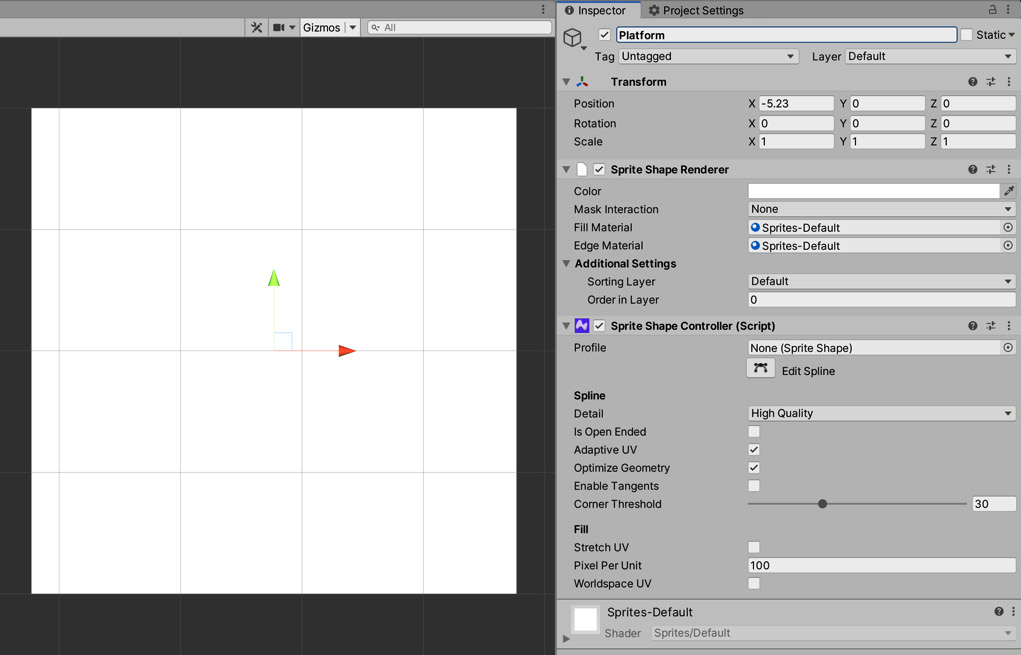
Figure 6.10 – The default look of a sprite shape
- Name the new object Platform.
- Assign the Platform profile to the Profile field on the Sprite Shape Controller component:

Figure 6.11 – Assigning a profile to the shape controller
With that done, you'll notice that the white square transforms. While it is still a square, it will now be using the textures we previously assigned to the profile. With this groundwork complete, now comes the fun bit – shaping the platforms.
- Select the Platform object in the Hierarchy.
- Click Edit Spline in the Inspector:

Figure 6.12 – Enabling the Spline Editor
- As the tooltip explains, this will let you edit the shape of the platform directly in the Scene view by dragging the designated points. Do this now to create a platform that looks similar to the one shown in Figure 6.13:

Figure 6.13 – Our first sprite-shaped platform
You can change the Tangent Mode setting to create uniquely shaped platforms by selecting a new mode in the Inspector, just below the Edit Spline button. Linear (the default option) does not create curves between the selected points. This is the option used to create the platform in Figure 6.13. Continuous mode creates a curve between the control point and its neighbors. In this mode, the angle between the points is always at 180 degrees. The last option is Broken Mirrored; this mode also creates curves between the selected point and its neighbors. However, the angle of the curve can be adjusted and is not necessarily always 180 degrees.
- Continue to experiment with the different Tangent Mode options to create a number of platforms. The platforms I've created are shown in Figure 6.14. I have used close-ended platforms here to add a bit of depth, but you can select the Is Open Ended option on the Sprite Shape Controller component to create flat, open platforms:
Tip
You can delete a point by selecting it and pressing the Delete button.
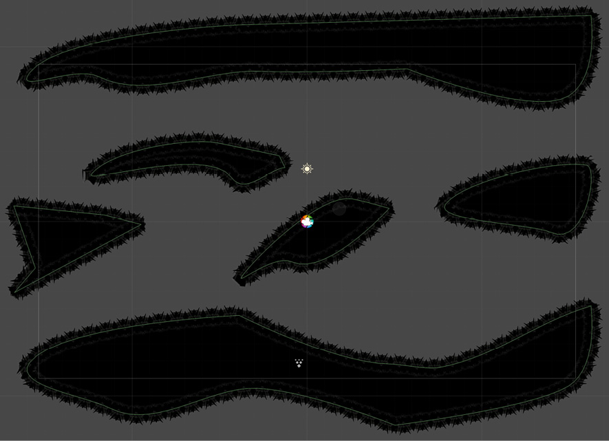
Figure 6.14 – The platforms for level four
- Add colliders to the platforms by selecting all of them in the Hierarchy panel and choosing Component | Physics 2D | Edge Collider 2D in the Inspector. This will automatically create colliders with the correct shape, as shown in Figure 6.14 by the green outlines.
- Drag the tex_level02_bck texture from the Project panel to the Scene and assign it the Position of 0, 0, 0 in the Inspector. This will be the background for the level:

Figure 6.15 – Adding a background
- To differentiate the background from other levels, make the background semitransparent and add a color tint by selecting the Color field on the Sprite Renderer component and entering 153, 255, 155, and 186 for the red, green, blue, and alpha (RGBA) values, respectively:

Figure 6.16 – Background color settings
- By making the background translucent, we can control the level's color scheme using the camera's Background color. Select the camera in the Hierarchy and change Projection to Orthographic (if not already), Clear Flags to Solid Color, and Background to a color of your choice. I've selected blue, as shown in Figure 6.17:

Figure 6.17 – Camera settings for level four
- Add the vine textures from the textures folder to add depth to the scene. Position and scale them as you see fit. You will now have a level that looks something like Figure 6.18:
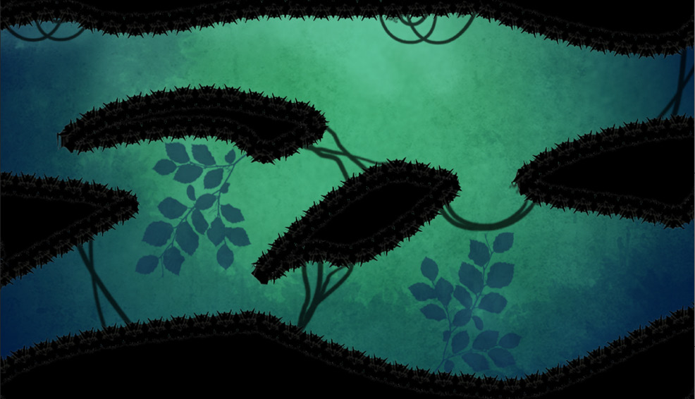
Figure 6.18 – The completed level
- Save the scene by selecting File | Save from the application menu and call it Level04.
And that's it, we've added three new levels to the game. The levels as they stand are relatively static, there are particle effects that add movement, but there are no moving interactive elements. We'll fix that now by adding moving platforms.
Implementing moving platforms
While the level structure is complete, they are relatively static environments. The only moving element is that of the player. We'll rectify this situation by creating a moving platform. The platform should move up and down continuously, and the player should be able to jump on it anytime to hitch a ride. We'll construct the object as a prefab so that it can be reused across multiple scenes. See Figure 6.19 for the result:
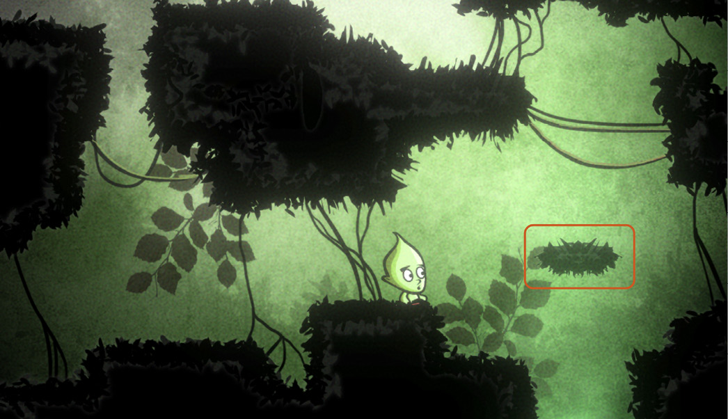
Figure 6.19 – Create a moving platform
Now that we have an idea of the end goal, let's start by creating the platform GameObject.
Creating the platform object
To create the platform object, take the following steps:
- Select the Platform texture in the Project panel.
- Select the Sprite (2D and UI) Texture Type option in the Inspector:

Figure 6.20 – Setting the texture type
- Set Sprite Mode to Single.
- Drag and drop the Platform texture to the scene.
- Set the Scale of the new object to (0.7, 0.5, 1):

Figure 6.21 – Building a moving platform
- Next, the platform should be a solid object, as we'll want the player to be able to stand on it, so we'll add a collider component. Select the Platform object in the scene and choose Component | Physics 2D | Box Collider 2D in the Inspector.
- Adjust the collider's Offset and Size values to make the collider match the size of the platform:

Figure 6.22 – Estimating the platform's physical size
- Finally, test the platform by entering Play mode and moving the player character to the platform. As you can see in Figure 6.23, the player should be able to stand on the platform:

Figure 6.23 – Testing platform collisions
Great, we have a platform that behaves mostly as expected. I say mostly because, for a moving platform, it's not very mobile. We'll fix that next by writing the scripts that will animate the platform.
Scripting platform movement
The platform so far is static and motionless. To fix this, we could create a predefined animation sequence using the Animation Editor. However, instead, we'll write a script. Frequently, when making animations, you'll often need to make decisions about which option is best: C# animations or baked animations. Typically, you'll tend to use a script when an animation is simple and must apply to many objects with slight variations. Create and add the following PingPongMotion.cs script to the platform object:
public class PingPongMotion : MonoBehaviour
{
public Vector3 MoveAxes = Vector2.zero;
public float Distance = 3f;
private Vector3 OrigPos = Vector3.zero;
void Start ()
{
OrigPos = transform.position;
}
void Update ()
{
transform.position = OrigPos + MoveAxes * Mathf.PingPong(Time. time, Distance);
}
}
The following points summarize the preceding code block:
- The PingPongMotion class is responsible for moving a GameObject back and forth from an original starting point.
- The Start function uses the OrigPos variable to record the starting position of the GameObject.
- The Update function relies on the Mathf.PingPong function to transition a value smoothly between a minimum and maximum. This function fluctuates a value between minimum and maximum repeatedly and continuously over time, allowing you to move objects linearly. For more information, see the Unity online documentation at http://docs.unity3d.com/ScriptReference/Mathf.PingPong.html.
Attach the completed script to the platform object in the scene. It can also be reused easily for any other object that should move up and down regularly (or left and right).
As you test the new platforms, you may notice that if the player falls off the platform and down one of the holes at the bottom of the level, nothing happens. We would expect the player to lose a life when they fall down these pits, and that's what we'll implement next.
Implementing player kill zones
A common scripted feature required by all scenes, but not yet implemented, is the kill zone. This is the functionality to mark out a region of 2D space in the level that, when entered by the player, will kill or damage them. This is an especially useful tool to kill the player whenever they fall down a hole in the ground. The kill zone will be required in most levels because nearly every level created so far contains pits and holes in the ground. To implement this functionality, take the following steps:
- Create a new and empty GameObject in any scene. It doesn't matter which scene because we'll be making a prefab object that can be reused anywhere. As previously mentioned, new GameObjects are created with the menu option, GameObject | Create Empty.
- Once created, name the object KillZone.
- Position the object at the world origin (0,0,0).
- Attach a Box Collider 2D component using the menu command, Component | Physics 2D | Box Collider 2D. The Box Collider will define the kill zone area.
- Make sure that the collider is configured as a trigger by checking the Is Trigger checkbox in the Inspector from the Box Collider 2D component, as shown in Figure 6.24:

Figure 6.24 – Creating a kill zone object and trigger
A trigger differs from a collider; colliders prevent objects from passing through, and triggers detect when objects pass through, allowing you to perform custom behaviors.
Next, create a new script called KillZone.cs, which should be attached to the kill zone object in the scene. This script will be responsible for damaging the player's health for as long as they are in the kill zone. At this stage, there are several ways to approach implementation. One way is to destroy the player as soon as they enter the zone. The other is to damage the player for as long as they are in the zone. The second method is preferred here because of its versatility and contribution toward code reuse. Specifically, we get the option to damage the player by reducing their health at a particular rate (if we need to), as well as killing the player instantly by increasing the rate at which it is reduced. Let's see this at work in the following code block:0
public class KillZone : MonoBehaviour
{
public float Damage = 100f;
void OnTriggerStay2D(Collider2D other)
{
if(!other.CompareTag("Player"))return;
if(PlayerControl.PlayerInstance!=null)
{
PlayerControl.Health -= Damage * Time.deltaTime;
}
}
}
The following points summarize the preceding code block:
- The KillZone class is responsible for continually damaging the player's health when a GameObject, tagged as Player, enters and remains within a trigger volume.
- The OnTriggerStay2D function is called automatically by Unity, once per frame, when an object with a Rigidbody enters and remains within a trigger volume. Thus, when a physics object enters the kill zone trigger, the OnTriggerStay2D function will be called as frequently as the Update function. More information on OnTriggerStay2D can be found in the online Unity documentation at http://docs.unity3d.com/ScriptReference/MonoBehaviour.OnTriggerStay2D.html.
- The Damage variable encodes the reduction of health per second for the player by adjusting the public static property, Health, which is part of the PlayerControl class. When Health reaches 0, the player will be destroyed.
To use the new script, do the following:
- Add the KillZone script to the KillZone object.
- To ensure that the player is killed instantly, increase the Damage to a very high number, such as 9000.
- Create a prefab from the KillZone object by dragging and dropping it from the scene's Hierarchy panel to the Project panel in the Prefab folder.
- Then, add the KillZone prefab to each level, adjusting the collider's size as needed.
We now have a method of reducing the player's health, yet the eventual player of our game has no way of knowing the current health status of the character. To fix this, we'll implement a UI health bar.
Creating the UI health bar
In the previous section, we introduced the first danger and hazard to the game: a zone that can damage and potentially kill the player. As a result, their health has the potential to reduce from its starting state. It's therefore useful both to us as developers and to gamers to visualize the health status. For this reason, let's focus on rendering the player's health to the screen as a UI health bar. Figure 6.25 offers a glimpse into the future, displaying the result of our work to come:

Figure 6.25 – Preparing to create the player health bar
We'll start by configuring a canvas object that will contain our new UI.
Preparing the scene for the UI
To get started, we'll create and configure a canvas object and associated UI camera:
- Create a new UI Canvas in the scene (any scene) by choosing GameObject | UI | Canvas from the application menu. The newly created Canvas object represents the surface on which the UI will be drawn.
Important Note
Adding a canvas object to a scene will automatically create an EventSystem object if one does not exist already. This object is essential for the proper use of the UI system; without it, interaction with the UI will not work. If you accidentally delete it, the EventSystem can be recreated by choosing GameObject | UI | Event System from the application menu.
- Next, we'll create a separate camera object for the UI, adding it as a child of the newly created Canvas. By creating a camera for UI rendering, we can apply camera effects and other image adjustments separately to the UI, if we need to. To create a camera as a child, right-click on the Canvas object in the Hierarchy panel and, from the context menu, choose Camera and rename the object as HUD_Cam:

Figure 6.26 – Creating a camera as a child object
- Now, configure the UI camera to be an Orthographic camera. We saw how to do this in the previous chapter, as well as earlier chapters too. Figure 6.27 displays the camera settings for an orthographic camera. Remember that an orthographic camera removes perspective and foreshortening effects from the render result, which is appropriate for UIs and other objects that live and work in screen space.
- The camera's Depth field, in the Inspector, should be higher than the main game camera to ensure that it renders on top of everything else. Otherwise, the UI could potentially render beneath and be ineffective in the game. Set it to 0 (the main camera depth defaults to -1):
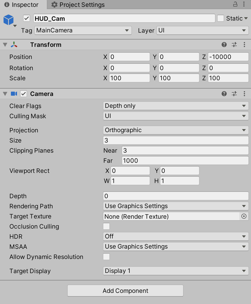
Figure 6.27 – Configuring an orthographic camera for UI rendering
The created camera is almost ready to go! However, right now, it's configured to render everything in the scene, just like any other camera. This means that the scene is effectively being rendered twice by two cameras. This is not only wasteful and poor for performance, but it also makes the second camera redundant. Instead, we want the first original camera to show everything in the scene, in terms of characters and environments, but to ignore UI objects, and the newly created UI camera should only show UI objects.
To fix this, do the following:
- Select the main game camera.
- From the Inspector, click on the Culling Mask drop-down list on the Camera component. From here, remove the checkmark for the UI layer. This drop-down list allows you to select layers to be ignored for the rendering from the selected camera:
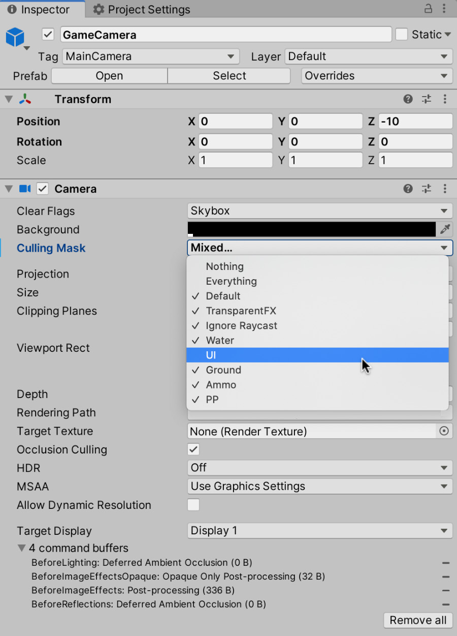
Figure 6.28 – Ignore the UI layer for the main camera
- Now, select the UI camera object and, for the Culling Mask field in the Camera component, select the Nothing option to deselect all options, and then enable the UI layer to render UI layer objects only, as shown in Figure 6.29:

Figure 6.29 – Ignoring all layers except the UI layer for the UI camera
By default, any newly created canvas is configured to work in the Screen Space Overlay mode, which means it renders on top of everything else in the scene that is not associated with any specific camera. In addition, all the UI elements will be sized and scaled based on this. To make our work simpler, let's start creating the UI by first configuring the Canvas object to work with the newly created UI camera:
- Select the Canvas object and, from the Canvas component in the Inspector, change Render Mode from Screen Space - Overlay to Screen Space - Camera.
- Drag and drop the UI camera object to the Render Camera field, as shown in Figure 6.30:
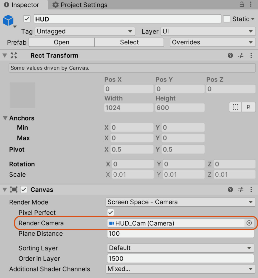
Figure 6.30 – Configuring the Canvas component for camera rendering
Next, let's configure the Canvas Scaler component, which is attached to the Canvas object. This component is responsible for how the UI appears when the screen size is changed. For our game, the UI should scale relative to the screen size:
- Change the UI Scale Mode dropdown to Scale With Screen Size.
- Enter a resolution of 1024 x 600 in the Reference Resolution field, as shown in Figure 6.31:

Figure 6.31 – Adjusting the Canvas Scaler component for responsive UI design
With the scene prepared for our game's UI, we can start creating and adding the elements required for our health interface.
Adding UI elements
Now we know that the UI elements will display correctly we can start creating them. We'll first add an image of the player:
- Create a new Image object by right-clicking on the Canvas object from the Hierarchy panel and choosing UI | Image from the context menu:

Figure 6.32 – Creating an image as a child object
- Select the new Image object.
- From the Inspector, on the Image component, drag and drop the player head sprite (spr_Head) from the Project panel to the Source Image field.
- Then, use the Rect Transform tool (T on the keyboard) to resize the image in place at the top-left corner of the screen, as shown in Figure 6.26:
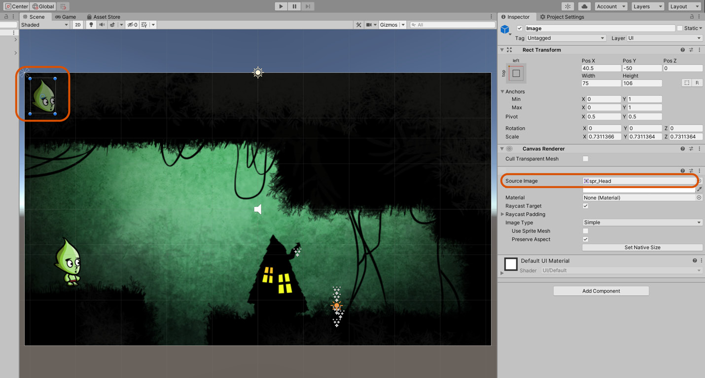
Figure 6.33 – Adding a head image to the UI Canvas
If you cannot see the added head image, remember to assign the UI layer to render by the UI camera. In addition, you may need to offset the UI camera back along the z axis to include the head sprite within the camera frustum (viewing area).
- Finally, anchor the head sprite to the top-left of the screen by clicking on the Anchor Presets button on the Rect Transform component from the Inspector and selecting top-left alignment. This locks the head sprite to the top left of the screen, ensuring that the interface will look consistent at multiple resolutions:
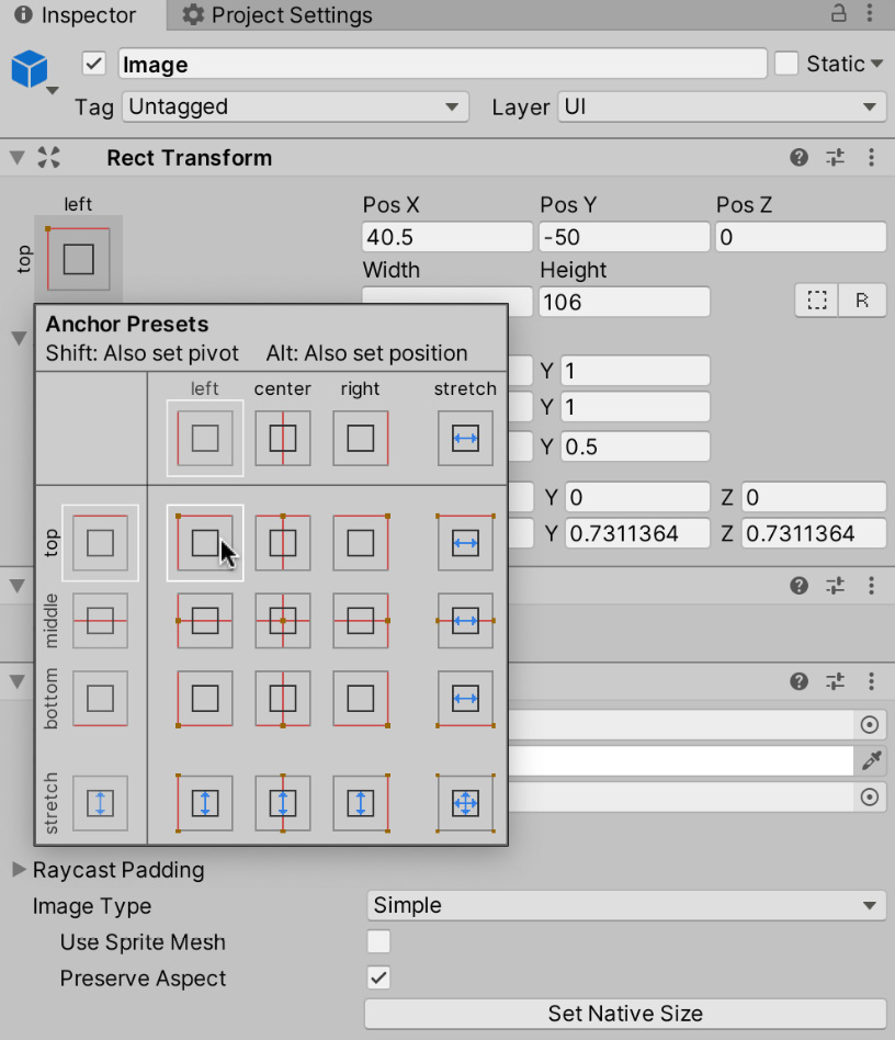
Figure 6.34 – Anchoring the head position
To create the health bar, take the following steps:
- Add a new Image object to the UI Canvas by right-clicking on the Canvas and selecting UI | Image from the context menu.
- For this object, leave the Source Image field empty and choose red for the Color field, RGB (255,0,0). This will represent the background or red status for the health bar when it's fully depleted.
- Then, use the Rect Transform tool to resize the bar as needed, once again anchoring it to the top-left corner of the screen, as shown in Figure 6.35:
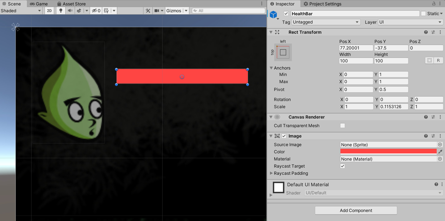
Figure 6.35 – Creating the red health status bar
The UI as it stands is static and doesn't update as the player takes damage. To fix this, we'll need to write a new script.
Scripting the health bar
To implement the health bar functionality, we're going to overlap two identical health bars on top of each other, one red and one green. We'll then scale the green bar as the health reduces so that it reveals the red bar underneath. Before scripting this behavior, further configuration is necessary. Let's change the pivot of the health bar away from the center and to the middle-left point—the point from which the health bar should scale as it reduces and increases. To do this, take the following steps:
- Select the HealthBar object in the Hierarchy panel.
- From the Inspector, enter a new Pivot value of 0 for X and 0.5 for Y, as shown in Figure 6.35.
Before we jump into writing code, there's one more thing we need to do: create the green overlay for the health bar. This can be accomplished by duplicating the current health bar:
- Duplicate the red health bar by right-clicking on the object in the Hierarchy panel and selecting Duplicate.
- Name the duplicate Health_Green and drag and drop it to appear beneath the red version in the Hierarchy panel list. This will render the object on top of the red health bar as the ordering of objects in the Hierarchy relates to the draw order for UI elements—lower-order objects are rendered on top of higher-order objects:

Figure 6.36 – Creating a duplicate green bar
Now, we need to make a new script file linking the width of the green bar to the health of the player. This means that reductions in health will reduce the width of the green bar, revealing the red bar beneath. Create a new script file named HealthBar.cs and attach it to the green bar:
public class HealthBar : MonoBehaviour
{
public float MaxSpeed = 10f;
private RectTransform ThisTransform = null;
…
void Update ()
{
float HealthUpdate = 0f;
if(PlayerControl.PlayerInstance!=null)
{
HealthUpdate = Mathf.MoveTowards(ThisTransform. rect.width, PlayerControl.Health, MaxSpeed);
}
ThisTransform.sizeDelta = new Vector2(Mathf. Clamp(HealthUpdate,0,100),ThisTransform.sizeDelta.y);
}
}
The following points summarize the preceding code block:
- The HealthBar class is responsible for reducing the width of the green health bar, based on the player's health. The green health bar is overlaid on top of the red health bar. Therefore, as the green bar's width decreases, more of the red health bar is exposed.
- We use the SizeDelta property of RectTransform to set the width of the health bar. More information on this property can be found online at https://docs.unity3d.com/ScriptReference/RectTransform-sizeDelta.html.
- The Mathf.MoveTowards function smoothly transitions the health bar's width from its existing to its destination width over time. The health bar width will decrease gradually, as opposed to instantly. More information can be found in the online Unity documentation at https://docs.unity3d.com/ScriptReference/Mathf.MoveTowards.html.
To use the script, do the following:
- Attach the HealthBar script to the green bar.
- Make a prefab of the UI objects by dragging and dropping the topmost Canvas object from the Hierarchy panel to the Project panel in the Prefab folder. Creating a prefab allows us to reuse the UI system across multiple scenes.
Now whenever the player takes damage, the UI will update accordingly! With every point of damage the player takes, the green bar will shrink, and more of the red bar will be shown. To properly test the UI, it would be useful to have something else in the game that can damage the player (I know we currently have kill zones, but they kill the player too quickly). Luckily for us, in the next chapter, we'll create gun turrets that will do precisely that.
Summary
By learning how to take advantage of sprite shaping, you have added a new tool to your game development belt. If you're not so artistically minded (I'm certainly not), the ability to use a small set of tiles to create a diverse range of environments is hugely useful. Even if you are terrific at creating game art (lucky you!), sprite shaping can help bring your art to life in ways that weren't possible before.
Many games rely on a health system of some variety, and the knowledge gained by implementing the system in this chapter will be useful for a long time to come, no matter what genre of game you're working on (although there are some exceptions; a health system in most sports games wouldn't make much sense, for example). By building on this system by creating a custom health UI, you've laid the foundation for creating a dynamic UI for games in the future. While we focused on creating a health bar in this chapter, using the same principles, you could just as easily create a UI for your score, or the number of collectibles obtained.
By adding platforms to the game, you've introduced the first dynamic element. This dynamism will be extended in the next chapter as we complete the game by adding gun turrets, an NPC, and a quest system.
Test your knowledge
Q1. OnTriggerExit2D is a function that runs...
A. Every frame
B. When an object leaves a trigger
C. When the player completes the level
D. When the level exits
Q2. To interact with the UI, you need a(n)…
A. EventSystem
B. Animation System
C. Collider
D. Component
Q3. Enumerations are good for...
A. Storing lists of values
B. Counting objects
C. Searching for objects
D. Sorting objects by name
Q4. You can pick a random number using…
A. Random.Range
B. SelectRandomNumber
C. ChooseRandom
D. GetRandomNumber
Further reading
For more information on Unity serialization, sprite shaping, and more, take a look at the following links: