
Chapter 8: Creating Artificial Intelligence
In this chapter, we'll start looking at specific gameplay elements rather than game genres. This project, unlike the previous three, will not be a game with a clear win and lose condition but will be a functional prototype that highlights a range of important coding techniques and ideas prevalent in the game development.
In the complete project, we'll have a Non-Player Character (NPC) that will patrol the level searching for the player using Unity's pathfinding tools, and when it finds the player, it will chase the player down until it is within range and mercilessly attack the player. Its behavior will be controlled using a Finite State Machine (FSM).
In this chapter, we'll cover the following:
- Importing assets from the Unity Asset Store (UAS)
- Creating the world that the player and NPC will cohabitate
- Generating a navigation mesh using NavMesh
- Animating the NPC using Unity's Mecanim system
- Writing a custom first-person controller
- Creating an animated waypoint system for the NPC to follow
To achieve our goals, we'll build on packages that we import from the Unity Asset Store. The UAS is an excellent resource that enables us to hit the ground running. By importing a terrain package, we don't need to construct the environment from scratch. Instead, we can change an existing terrain to fit our needs; and we'll do the same for the NPC by building on an existing package.
Once we've created the terrain, added an animated NPC, and created a waypoint system, we'll add the player to the world. In the previous chapters, we've relied on the first-person character included with the standard assets. However, by creating a customized version in this chapter, we will gain an understanding of what goes into creating a character controller and have a solid foundation that we can extend in future projects.
We'll start by examining the complete project before importing the required assets for the UAS.
Technical requirements
In this chapter, you will start a new project that is not a direct continuation of previous projects. However, as with previous chapters, this chapter assumes that you have not only completed the previous projects but also have a good and basic knowledge of C# scripting generally, though not necessarily in Unity.
You can download the example code files for this book from GitHub at https://github.com/PacktPublishing/Unity-2020-By-Example. Once downloaded, you can find the AI project in the Chapter08/End folder.
This chapter uses two assets from the Unity Asset Store, which, along with their author details, can be found at the following links:
- https://assetstore.unity.com/packages/3d/characters/animals/meshtint-free-chick-mega-toon-series-152777
- https://assetstore.unity.com/packages/3d/environments/landscapes/low-poly-simple-nature-pack-162153
Looking ahead – an overview of the project
In this chapter, we'll start by working on a first-person game in which the player character can explore an environment. The terrain features hills, valleys, and varied terrain elements.
The player will not be alone in the world. An NPC in the form of a baby chicken, that is, a chick, will also move around the environment. The Artificial Intelligence (AI) for the NPC will operate using an FSM with three states: Patrol, Chase, and Attack. The chick will wander around (Patrol mode) searching for the player. If the player is sighted, the NPC will chase and pursue the player (Chase mode). If, during the chase, the enemy loses sight of the player, they will return to patrolling. On the other hand, if the enemy approaches the player during the chase, the enemy will attack the player (Attack mode).
See Figure 8.1 for a sneak peek of the completed project:

Figure 8.1 - Building a world with intelligent NPCs
Now that we have an idea of what we want to achieve, we can take the first step toward the goal by importing external assets to jump-start our project.
Importing assets
As with all of the previous projects, there will be some assets we don't create ourselves. For this project, we will import packages for the terrain and character models as creating them is not crucial for understanding AI. We'll import those assets into an empty project:
- Create a new 3D project. The details on this are covered in Chapter 1, Exploring the Fundamentals of Unity.
- Navigate to the UAS online at https://assetstore.unity.com.
- Search for Low-Poly Simple Nature Pack. This pack will become the terrain for our AI agents.
- Select Add to My Assets as shown in Figure 8.2:
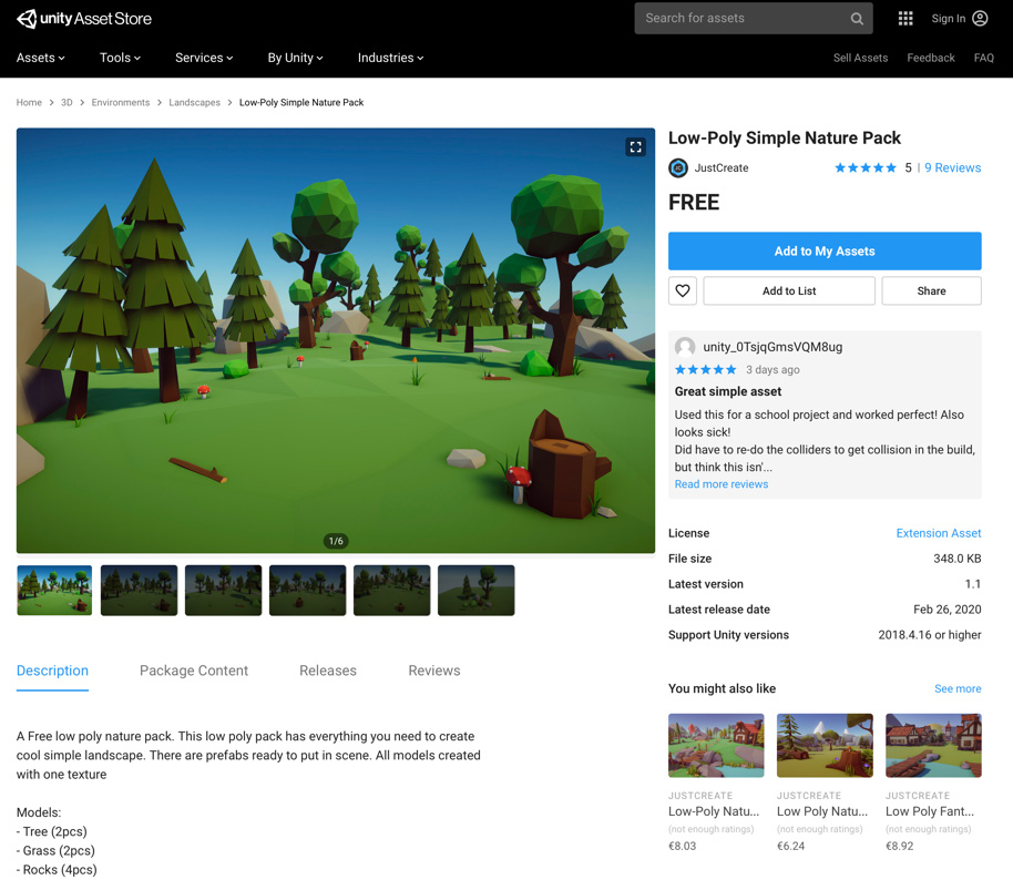
Figure 8.2 - Adding the terrain pack to your asset collection
We also need a terrifying enemy that will patrol and chase the player—striking fear into anyone that enters its territory. Once again, we'll use a premade asset for this, although you could create your own by using the 3D modeling software.
- In the UAS, search for Chick Mega Toon Series and once again click on Add to My Assets:

Figure 8.3 - Adding the character pack to your asset collection
It may not look so scary now, but wait until this chick is chasing you down in-game!
- Back in Unity, we need to import the packages into our project. Open the Package Manager by selecting Window | Package Manager from the Application menu.
- Find the terrain package in the package explorer and click on Import:

Figure 8.4 - Importing the terrain pack
- Repeat the process for the character package, which should also be visible in the package list.
We have now imported all of the external packages that we require for now. It's time to start molding them to make them our own. We'll start by creating the terrain that will be our NPC's home.
Constructing the terrain
Now that we've imported all of the assets we require, we can start preparing the scene for our AI agent (also known as the terrifying chick for reasons that will become apparent):
- The nature pack provides an example scene that we can alter to suit our needs. Navigate to Assets/NaturePackLite/Scenes in the Project panel.
- Double-click the Demo scene to open it:
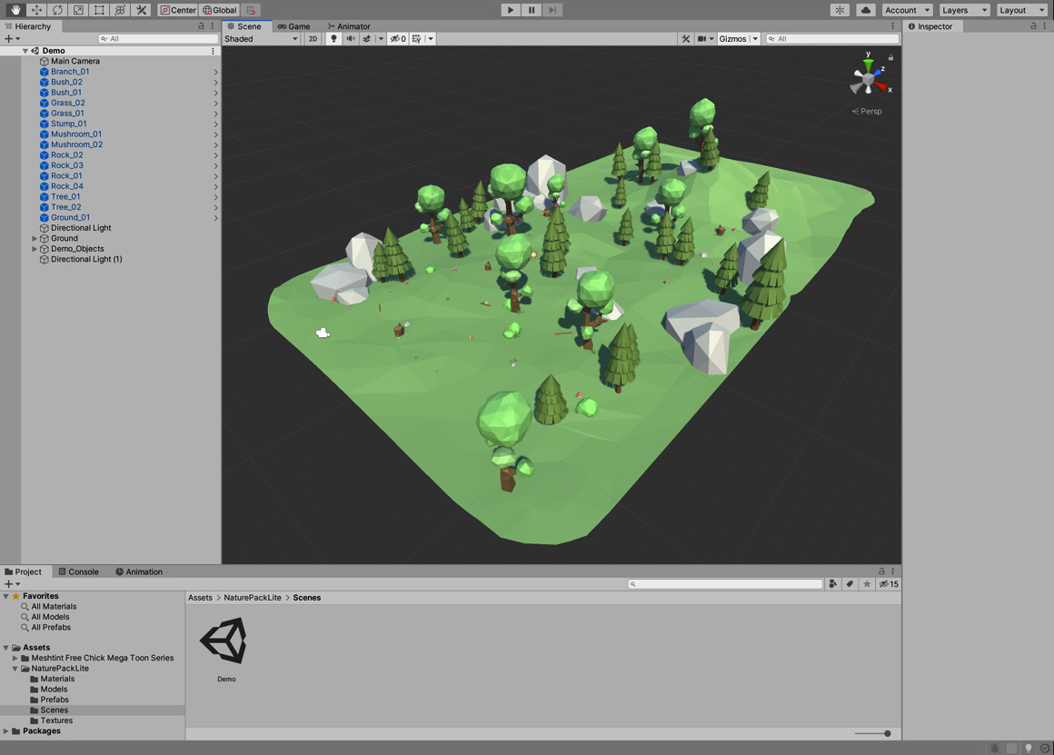
Figure 8.5 - The nature pack example scene
- You will most likely have noticed that the scene consists of two separate islands. We only require one. Select all items associated with the smaller island from the Hierarchy as shown in Figure 8.6 and delete them:

Figure 8.6 - Deleting all items associated with the smaller island
Next, we want to increase the size of the terrain to provide more space for the terrifying chick and the player to walk around.
- Select Ground_01 from the Hierarchy and duplicate it by pressing Ctrl + D (Windows) or cmd + D (macOS). It is a child object of the Ground object.
- Move the new object to Position -25.57, -3.76, 21. You can do this with the Move Tool but will most likely find it easier to type the values manually in the Inspector.
- Reset the Rotation of the new object to 0, 0, 0:
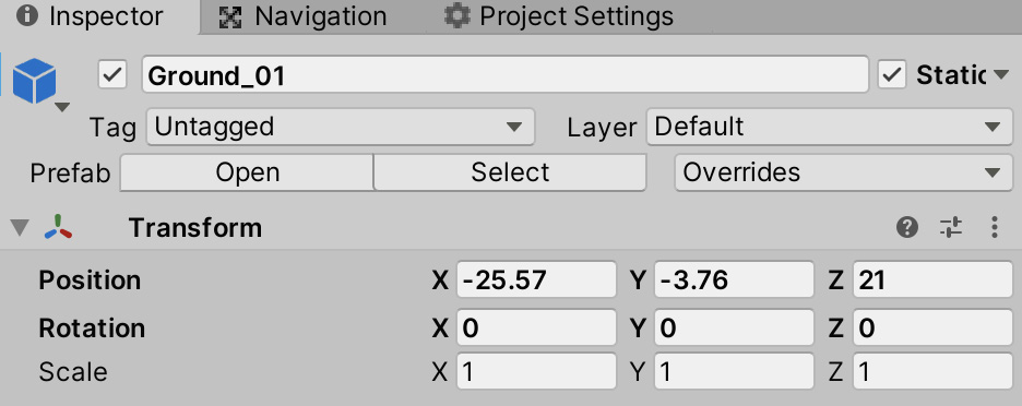
Figure 8.7 - Duplicated ground settings
- Select Ground_02 from the Hierarchy (again, it is a child object of the Ground object).
- Duplicate the object.
- Position the object at -25.57, -3.47, -1.83.
- Set the object's Rotation to 0, 180, 0.
You should now have a scene that looks similar to Figure 8.8:
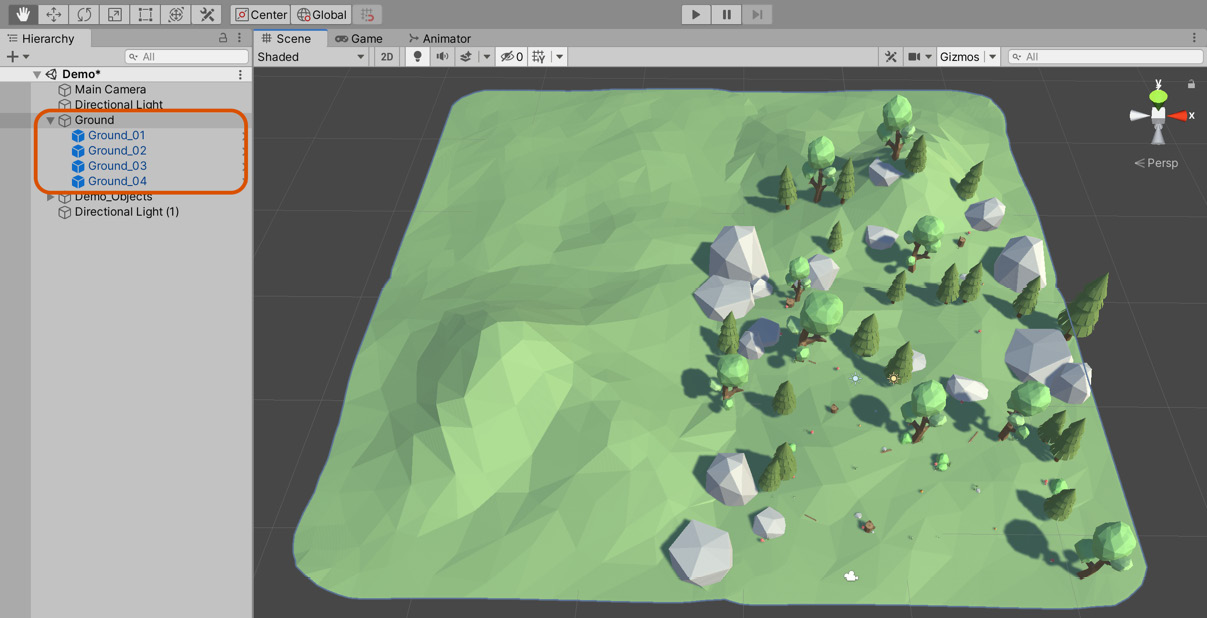
Figure 8.8 - The scene with extended terrain
- Any player of our game will notice pretty quickly that half the terrain does not have any trees or other decorative objects. The next step is to re-arrange the objects so they're spread out over all four terrain objects. Feel free to duplicate objects as you see fit. My arrangement is shown in Figure 8.9:
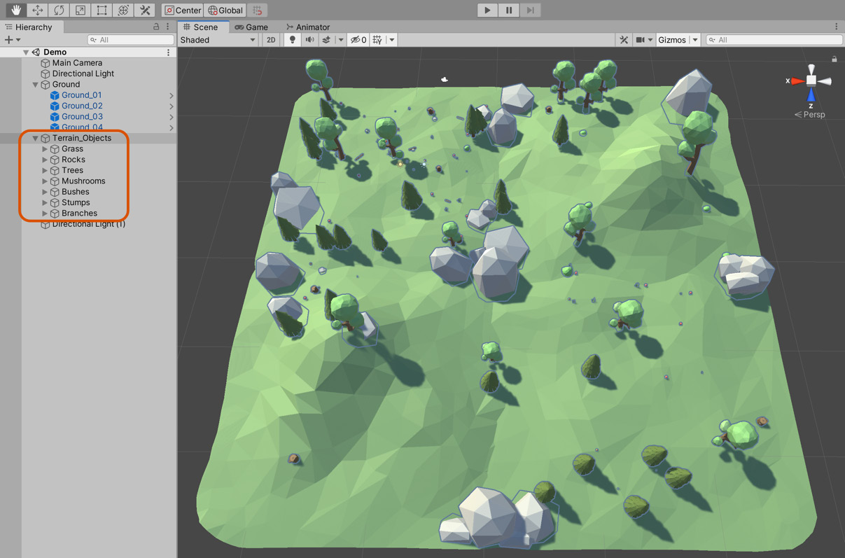
Figure 8.9 - The scene with extended terrain and additional objects
By creating empty parent objects, I've also arranged the objects into the following categories in the Hierarchy:
- Grass
- Rocks
- Trees
- Mushrooms
- Bushes
- Stumps
- Branches
This arrangement will make it easier to define which objects should block the NPC movement (trees, rocks, and stumps) and which objects the terrifying chick should be able to walk through (grass, mushrooms, bushes, and branches).
You may wish to continue to experiment with the terrain tool or look on the UAS for assets to improve the level aesthetically. However, the world terrain is now fit for our purposes, and we can now start implementing features that will help us to achieve the main aim of this project. As a reminder, our goal is to create an enemy character that can wander freely around the terrain and will chase and attack the player whenever the player enters their field of view.
Now that we've created the level, we get one step closer to that goal by configuring the level for pathfinding using a navigation mesh.
Generating the navigation mesh
The terrain is bumpy and features several hills, mountains, dips, and inclines. For an NPC character to navigate this terrain successfully, there are many complexities involved. For example, an NPC cannot necessarily travel in a straight line from point A to point B because doing so would cause the NPC to pass through solid objects and over terrain that should be impassable. The NPC needs to maneuver intelligently around, under, and over appropriate parts of the terrain. This illusion of intelligence is essential to create believable characters that inhabit a world. The computational processes involved in calculating a suitable path for an NPC is called pathfinding, and the method of making the character travel the calculated route is called navigation. Unity comes with built-in pathfinding and navigation features, making it easy for NPCs to calculate and travel paths.
To prepare our characters for navigation, a Navigation Mesh must be generated. This mesh is a special asset included in the scene, which uses non-rendered geometry to approximate the total walkable surface of a scene. This geometry, rather than the one visible to the player, is then used to calculate possible routes.
Important note
The navigation mesh is usually a much-simplified version of the actual geometry to reduce the complexity of the pathfinding calculations. The trade-off of this approach is that occasionally the navigation and terrain meshes can diverge to the extent that a character can walk a path that doesn't exist or won't take a route that they should. For this reason, it is vital that if the terrain is changed, the navigation mesh is regenerated.
For this process to work effectively, all non-movable floor meshes in the scene should be marked as Navigation Static. To do this, follow these steps:
- Select the terrain (Ground_01, Ground_02, Ground_03, and Ground_04) from the Hierarchy panel.
- From the Inspector, click on the Static checkbox, as shown in Figure 8.10:
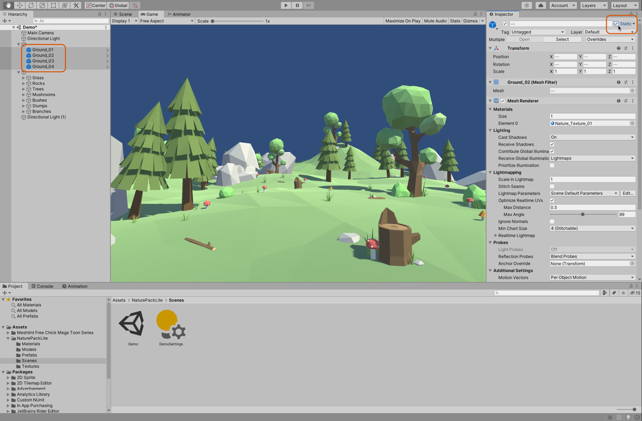
Figure 8.10 - Marking non-movable floor objects as static
By ticking the Static checkbox, you're enabling several options. If you click the arrow next to the Static label, it will list the options and allow you to enable and disable them individually. For our needs, we only need the Navigation Static option selected. However, as the object will not be moving at all in the scene, enabling all of the options provides several benefits, including a possible reduced rendering cost and the ability to precalculate lighting data for improved runtime performance. For these reasons, it is a good practice to mark all of the non-moving objects as static.
Tip
For more information on the individual static options, see the online documentation at https://docs.unity3d.com/Manual/StaticObjects.html.
Now that we've marked our terrain as static, we can now generate a navigation mesh by doing the following:
- Select Window | AI | Navigation from the Application menu. The purpose of the Navigation window is to generate a low-fidelity terrain mesh that approximates the level floor.
- Click on the Bake tab to access the main navigation settings. From this panel, you can control a range of settings to influence Navigation Mesh (NavMesh) generation:
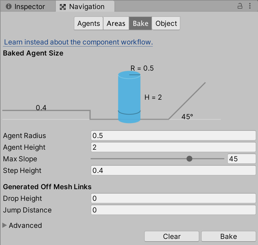
Figure 8.11 - The Bake tab contains the main settings for Navigation Mesh generation
The Bake tab contains a number of settings related to generating the navigation mesh:
- Agent Radius is the average radius of an agent. This setting defines how close an agent can get to the rocks, trees, and other obstacles in our map. It also determines how close the agent can get to the edge of the world without falling off.
- Agent Height is the average height of an agent. This setting currently does not affect us as it is used to define how low a space (for example, a tunnel) the agent can enter, and our terrain does not have any overhead obstacles. Even though it doesn't relate to us currently, it is a good practice to set a suitable value here in case we introduce such obstacles in the future.
- Max Slope defines the maximum angle of a slope that an agent can comfortably walk up.
- Step Height defines the maximum height of an obstacle that the agent can step on.
Important note
The Generated Off Mesh Links settings can safely be ignored as they are used to define how an agent can move between two disconnected meshes, and our terrain meshes are connected.
To get started, let's generate an initial Navigation Mesh to see how the default settings look. We can easily erase and regenerate the mesh under new settings if needed.
- Click on the Bake button (not the tab). When you do this, a default Navigation Mesh is generated and appears in blue above the terrain from the Scene viewport, as shown in Figure 8.12:

Figure 8.12 - A default Navigation Mesh
The blue area is the navigable terrain. You'll probably notice straight away that we have one problem: the navigation mesh doesn't take into account any of our other objects such as the rocks and trees. To fix this, we also need to mark them as Static:
- Select all of the objects that should hinder movement in the Hierarchy panel. This includes trees, rocks, and stumps.
- Once again, enable the Static checkbox in the Inspector.
- Go back to the Navigation panel and click Bake again. You'll now have a navigation mesh that looks similar to Figure 8.13:

Figure 8.13 - A Navigation Mesh with obstacles
The NavMesh asset itself is stored in a folder matching the scene name. When selected from the Project panel, you can preview various read-only properties describing the Navigation Mesh, such as the Height and Walkable Radius settings:

Figure 8.14 - Previewing Navigation Mesh properties from the Project panel
Next, we'll adjust the agent specific settings as our agent is relatively short and has a small radius. The Agent Radius setting is particularly important as it controls how large an average agent (NPC) is, and it affects how close the Navigation Mesh can expand toward the surrounding mesh floor and its edges. Lower settings allow the mesh to encroach nearer to the mesh edges, resulting in an expanded navigation mesh:
- Set Agent Radius to 0.3.
- Set Agent Height to 0.5.
- Set Max Slope to 30.
- Set Step Height to 0.5.
- Click on Bake again to observe the result. It should not vary too much from the previous navigation mesh but should have more appropriate paths for our small chick.
Tip
There are many tools available that extend or improve the NavMesh system. A popular one is NavMeshComponents. It's simple to use and is released and maintained by Unity. With NavMeshComponents, you can have multiple agent profiles, create dynamic navigation meshes that can be updated during play, and generate meshes during runtime for procedurally generated levels. For more information, see the GitHub page at https://github.com/Unity-Technologies/NavMeshComponents.
Congratulations! You have now constructed a Navigation Mesh for the level that our NPC will eventually use to traverse the environment either following waypoints or chasing the player down. Before the NPC can do this, we first need to add it to the scene, which we will do now.
Implementing the NPC
With the foundation complete, we can now add the character that will eventually patrol the area and chase the player. As previously mentioned, we have picked an asset that will strike terror into the heart of the player as they are stalked mercilessly by the Toon Chick:
- Locate the Toon Chick prefab in the Assets/Meshtint Free Chick Mega Toon Series/Prefabs folder in the Project panel. This folder was added when we imported the Toon Chick package:
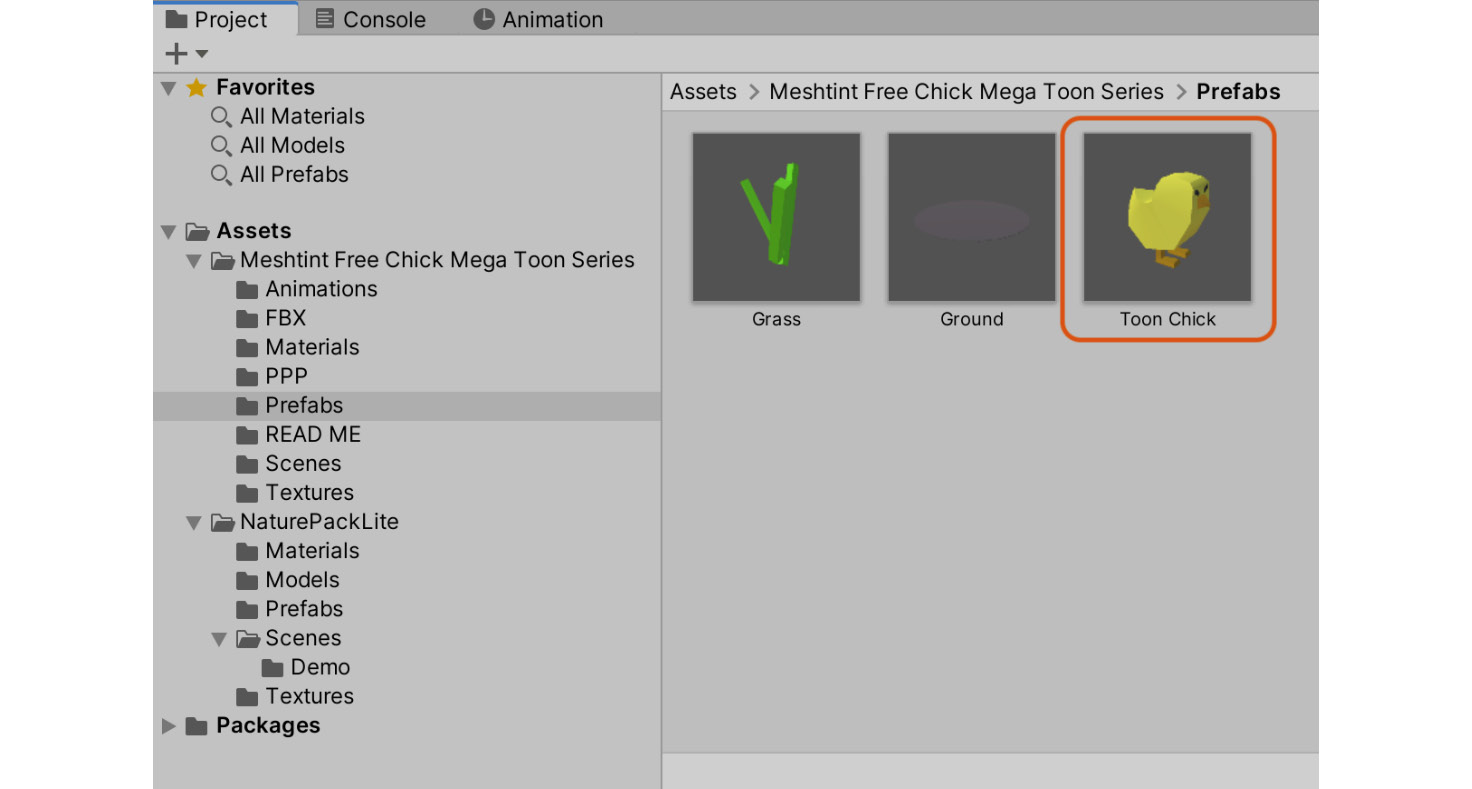
Figure 8.15 - The Toon Chick prefab
We'll refine this prefab by adding our own pathfinding logic.
- Drag and drop the prefab to the Scene view:
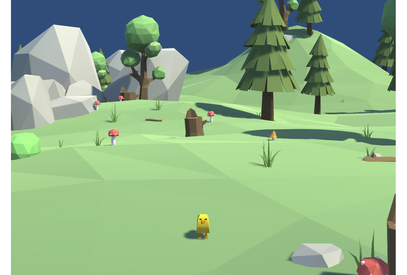
Figure 8.16 - The Toon Chick in the scene, looking at us ominously
- Select the Toon Chick from the Hierarchy.
- As the chick will be moving around the environment, we'll add a Rigidbody. In the Inspector, select Add Component | Physics | Rigidbody.
- On the Rigidbody component, under the Constraints heading, Freeze Rotation on the X and Z axes. Freezing these axes will prevent the chick from rolling over while still allowing for the chick to face different directions by rotating the Y axis.
- To prevent the chick from falling through the floor, we need to add a collider. Select Add Component | Physics | Capsule Collider.
- Adjust the colliders Center to 0, 0.2, 0, its Radius to 0.15, and its Height to 0.4:

Figure 8.17 - The collider and Rigidbody settings
- The NPC should navigate and walk around the terrain intelligently using the Navigation Mesh generated for the level. For this, a Nav Mesh Agent component should be attached to the character. Select Add Component | Navigation | Nav Mesh Agent. The Nav Mesh Agent component contains both pathfinding and steering (navigation) behaviors that allow a GameObject to move around a Navigation Mesh.
By default, the Navigation Mesh assigns a Cylinder Collision volume to the Agent—the object that will navigate and move around. This volume is not a collider that acts with the physics system, but a pseudo-collider used to determine when the character nears the edge of a navigation mesh and how they collide with other agents in the scene. We don't have any other agents yet, but we could always add more in the future. Let's configure that collider now, on the Nav Mesh Agent component:
- Set the Height to 0.4.
- Set the Radius to 0.2.
- Set the Base Offset to -0.09. This setting moves the collider up slightly, so the chick doesn't look like it is floating.
We should also update the settings related to how quickly the chick moves through the environment:
- Set the Speed to 1.5 to cap the chick's maximum movement speed.
- Set the Acceleration to 2 to define how quickly the chick can go from stationary to maximum speed.
- Set the Angular Speed to 60 to determine how quickly the chick can turn around.
These settings (shown in Figure 8.18) better approximate the chick's small stature:

Figure 8.18 - The Agent Nav Mesh Agent
Great! We have everything that we need for the NPC to move through the environment apart from a destination. Let's fix that now.
Testing navigation
To test that our navigation mesh and settings are working correctly, we'll create an object for the chick to seek in the environment, using pathfinding and steering to reach the goal. To implement this behavior, we'll also need to write a new script:
- Select GameObject | Create Empty from the Application menu to create a new empty object, which will act as a target object.
- Name the new object Destination.
- Assign it a Gizmo icon to make it visible in the viewport by clicking on the cube icon at the top-left of the Inspector and then choose an icon representation:
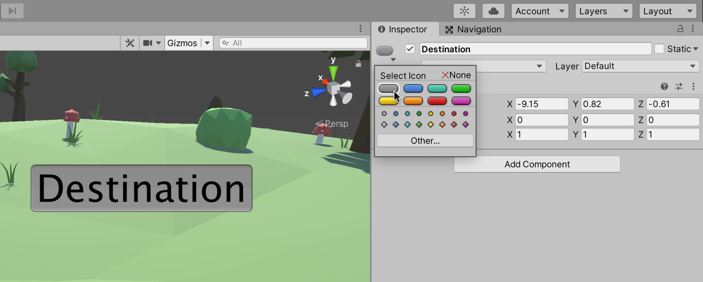
Figure 8.19 - Assigning an icon to the Destination object
- Next, create a new C# script file called FollowDestination.cs:
using UnityEngine;
using UnityEngine.AI;
[RequireComponent(typeof(NavMeshAgent))]
public class FollowDestination : MonoBehaviour
{
public Transform Destination = null;
private NavMeshAgent ThisAgent = null;
void Awake()
{
ThisAgent = GetComponent<NavMeshAgent>();
}
void Update()
{
ThisAgent.SetDestination(Destination.position);
}
}
The following points summarize the code sample:
For the script to work, a NavMeshAgent component is required, without which it would throw a runtime error. The RequireComponent attribute is useful to prevent these types of errors from happening. Because we've added the RequireComponent attribute, if the object does not already have a NavMeshAgent component, Unity will add one for us.
Important note
The RequireComponent attribute does not work retroactively. For example, if this script (minus the attribute) was already attached to an object without a NavMesh component, then we added the RequireComponent attribute, Unity would not attempt to add the missing component to the existing object.
The Destination variable maintains the destination object.
In every frame SetDestination is called on the NavMeshAgent component. This function will update the agent's destination and trigger the calculation of a new path, which can take a few frames to complete. While we're not doing it here for the sake of simplicity, we should first check whether the destination has moved before calling the SetDestination function to reduce unnecessary path calculations.
- Attach the script to the Toon Chick object in the scene.
- Drag and drop the Destination object to the Destination slot on the FollowDestination component in the Inspector, as shown in Figure 8.20:

Figure 8.20 - Configuring a FollowDestination object
During gameplay, move the destination object around via the Scene tab and see how the chick responds. The NPC should continually chase the Destination object. In addition, if you play the game with the Navigation window open and the NPC selected in the Hierarchy panel, the Scene view will display diagnostic information and gizmos, allowing you to preview and visualize the route calculated by the chick:

Figure 8.21 - Testing NPC navigation
You may have noticed that the environment in which the chick moves is not animated. No matter what speed the chick travels, its feet remain stationary. We'll rectify this now.
Animating the NPC
At the moment, the chick floats around the scene without a walking or running animation. We'll change that now by animating the chick as it walks around the scene. The chick will transition between a walking and running animation depending on its movement speed. Luckily for us, the package we imported comes with several premade animations, so we don't need to start from scratch. Instead, we'll focus on how to apply these animations to the chick, in two different ways. First, we will create separate states to represent each animation, switching between a walking and running animation based on the chick's movement speed. Then, we will look at a method of seamlessly transitioning between these two animations using a Blend Tree.
Creating animation states
Unity's animation system (also known as Mecanim) has two main panels to help us to develop animations, that is, the Animator and Animation panel. In this section, we'll look at the Animator panel, which controls how and when animations play.
Let's start by examining the animations currently associated with the chick object:
- With the Toon Chick object selected, open the Animator panel by selecting Window | Animation | Animator from the Application menu:

Figure 8.22 - Animator window
The Animator window has two main sections: The State Layout area and the Parameters or Layers view. Mecanim uses an FSM to manage its animation states, and this screen is a visual representation of that.
Important note
We'll go into more detail on FSMs in the next chapter when we write a custom FSM for the chick's behavioral states, that is, the Patrol, Chase, and Attack states. For now, it's enough to know that a state machine provides several distinct states and a method of transitioning between them based on specific conditions. It's a versatile pattern used for many different applications.
The rectangles in the state layout area represent a distinct animation state for a particular object (the object doesn't necessarily have to be a character, as we'll see later in this chapter). They are building blocks we can use to create complex animations. The white arrows between the states are user-defined transitions. One state can only transition to another if we define a conditional transition; there will be more on this very shortly when we create our own transitions.
The parameters in the Parameters list can be of the float, int, bool, or trigger type and are used as conditions for the transitions between animations. Based on whether a parameter is set to true or false (bool) or is greater or less than a specified amount (int and float), a transition can occur. As mentioned, you can also transition to an animation based on a trigger. You can think of a trigger as being similar to a Boolean, except that when we set it to true (that is, triggered), it is automatically reverted to false and stays in that state until triggered again. We'll discuss these parameters in more detail later in this chapter when we write a script that will set a parameter based on the chick's movement speed.
- Delete all user-created states we don't require by right-clicking on each one and selecting Delete. Delete the Walk W Root, Run W Root, Jump In Place, Idle, and Eat states. We will be left with the Walk In Place, Run In Place, and Jump W Root animations as shown in Figure 8.23. The walk and run animations will be selected based on the movement speed of the NPC, and the jumping animation will be used as an attack animation in the next chapter:

Figure 8.23 - All unnecessary animation states removed
You can't delete the states provided by Unity, that is, Any State, Entry, and Exit. They provide unique functionality:
- By creating a transition from the Entry state to another state, the state is marked as the entry point for the animation system and will be the first one played. You can have several entry states, each with different conditions. We'll see how to create a default state shortly.
- By creating a transition from a state to the Exit state, if that condition is met, the animation system will exit and then somewhat surprisingly re-enter the state machine at the Enter state, effectively creating a looping structure.
- By creating a transition from Any State to another state, you are stating that if this condition is met, no matter which state we are currently in, transition to this new state.
- As well as deleting unneeded states, we'll also remove any unnecessary parameters. As previously stated, we use parameters as criteria for transitioning from one state to another. Currently, we are only concerned with the transition between walking and running. We'll look at attacking in the next chapter and then add a new parameter, but for now, we only need one parameter. Delete all parameters apart from Run by right-clicking each item from the Parameters list and selecting Delete as shown in Figure 8.23:

Figure 8.24 - Deleting parameters
Now that we have the minimum number of states and parameters that we require, we can start modifying the functionality to meet our needs. Depending on the order in which the states were deleted, Unity may have changed the default state. The default state is the first state entered and is highlighted in orange. As shown in Figure 8.23, the default state is Jump W Root. As we don't want our chick to jump as soon as the game starts, let's change the initial state to something more suitable:
- Right-click the Walk In Place state.
- Select Set as Layer Default State.
The chick will start the game moving toward the Destination object, so having the walking animation also playing at the start of the game suits our needs perfectly:

Figure 8.25 - New default state
You will most likely have noticed that we were setting this state as the default state for this layer. Unity allows you to create different state machines for different layers. This functionality could be used, for example, if we had a complex character with different animations for different body parts. Layers are a big topic in themselves and one that is not required for this or any other project in this book. For more information on layers, see the Further reading section, where links to additional resources on this topic are included.
Tip
You can rearrange the states by clicking and dragging. This functionality comes in very handy as you add more states.
If you test the game now, you will see that the walking animation does indeed play as the chick moves around the environment, but you'll also notice that the run animation never plays. Depending on the speed of the chick, the running animation will be more appropriate, so we need to create a transition from the walking to the running animation:
- Right-click Walk In Place and select Make Transition. This will attach an arrow to your cursor, as shown in Figure 8.26:

Figure 8.26 - Creating a transition between animation states
- Drag the arrow to the Run In Place state and left-click to assign the transition. The arrow will now point from Walk In Place to Run In Place.
- We'll also want the chick to be able to transition from running to walking, so repeat the process but start from Run In Place to make two arrows, as shown in Figure 8.27:

Figure 8.27 - Two-way transition between the Walk and Run states
We've now created a two-way transition. By default, a transition will happen whenever the animation has played a specified amount. Therefore, as our two-way transition now stands, the chick would walk a bit before running and then go back to walking with the cycle repeating indefinitely. We'll want to control this transition through code, but before we can do that, we will need to configure the conditions:
- Select the arrow pointing from Walk In Place to Run In Place (the bottom arrow in Figure 8.27).
We can then use the Inspector panel to configure the settings for this transition. The window (shown in Figure 8.28) has several settings related to transitions, which include the following:
Has Exit Time: If checked, the transition can only happen after a specified time. If not selected, a transition condition must be specified.
Exit Time: This value specifies the normalized time at which the transition should occur. If there are conditions specified, they must also be met before the transition can happen.
Fixed Duration: If checked, the Transition Duration value is interpreted in seconds. If not checked, the Transition Duration value represents a fraction of the normalized time of the animation, for example, 0.25 equals 25 percent.
Transition Duration: This is the length of the transition in either seconds or as a normalized percentage.
Transition Offset: This is the normalized start time in the target state. For example, if you set a value of 0.5 when the transition occurs, the new animation will start playing halfway through.
Conditions: You can set conditions based on parameters specified in the Parameters list as shown in Figure 8.24. We'll see how to do this shortly.
- In the Inspector, untick Has Exit Time as we don't want the transition to occur when the animation has played a specified amount.
- Now that the transition won't occur based on an exit time, we need to specify a condition. Under Conditions, select the + sign to add a new condition:

Figure 8.28 - Creating a transition condition
- Select the condition Run and ensure the state is set to true.
The list of possible conditions here matches the parameter list. As we only have the Run parameter, this will be the only option. Configuring the condition as true here signifies that we need to set this parameter to true in our code for this transition to take effect. We'll see how to do that shortly.
Tip
We could have used a float parameter to store the chick's velocity. We could have then transitioned from walking to a running animation if this velocity parameter was greater than a specified amount (and transitioned back to walking when it becomes less than that amount).
We need to repeat the process but for the transition from Run In Place to Walk In Place:
- Select the other arrow pointing from Run In Place to Walk In Place.
- Once again, untick Has Exit time and add the Condition as Run. However, this time, set it to false, as shown in Figure 8.29. Now, whenever we set the Run parameter to false in our code, the chick will transition from a running to a walking animation:

Figure 8.29 - Transition settings
We now have two animations and two transitions. The walk animation will play first, and when the parameter Run is set to true, then the run animation will play. Once in the run state, if the Run parameter is then set to false, the run state will transition back to the walking state. Setting this parameter is the last thing we need to do to set up our animation system. We'll do this now using a script:
- Create a new script called AnimationController in the Script folder:
using UnityEngine;
using UnityEngine.AI;
[RequireComponent(typeof(NavMeshAgent), typeof(Animator))]
public class AnimationController : MonoBehaviour
{
public float RunVelocity = 0.1f;
public string AnimationRunParamName = "Run";
private NavMeshAgent ThisNavMeshAgent = null;
private Animator ThisAnimator = null;
void Awake()
{
ThisNavMeshAgent = GetComponent<NavMeshAgent>();
ThisAnimator = GetComponent<Animator>();
}
void Update()
{
ThisAnimator.SetBool(AnimationRunParamName, ThisNavMeshAgent.velocity.magnitude > RunVelocity);
}
}
The following points summarize the code sample:
The script requires access to the NavMeshAgent and Animator components, so the RequireComponent attribute is added before the class declaration. As you can see, you do not need separate attribute calls for each component.
The RunVelocity variable controls the running speed cut off. If the velocity of the NPC is above this value, then the Run animation parameter is set to true.
The object's velocity is checked in the Update function by retrieving the magnitude of the NavMeshAgents velocity and comparing that to RunVelocity. For more information on the magnitude of a vector, see the online documentation at https://docs.unity3d.com/ScriptReference/Vector3-magnitude.html.
Calling SetBool on the animation component and passing in AnimationRunParamName sets the state of the Run parameter. If the agent's velocity is greater than the predefined RunVelocity variable, then the Run parameter is set to true, and the run animation is played. Otherwise, it is set to false, and the walk animation is played.
- Add script to the Toon Chick object in the Hierarchy.
Great! Now the chick will walk rather than float around the environment. To properly test that our animation changes are working as intended and to extend the chick's behavioral repertoire, we will soon add the ability to patrol the environment, leaving no stone unturned in its search for the player. However, before we move away from discussion animations, we will briefly go over how to use Blend Trees, a useful tool for creating natural-looking animation transitions.
Using Blend Trees
In the next chapter, we'll be setting the animation state based on which AI state we are in, for example, if we're in a chase state, we'll tell the animator to play the run animation. Having distinct animation states, such as the ones we created in the previous section, works perfectly for us. However, there is also another way of transitioning between animations that is worth covering. You have probably guessed from the title of this section, but I'm talking about Blend Trees. Using a Blend Tree, we can blend two (or more) animations to create a more natural transition. For the chick, we will create a Blend Tree that combines its walk and run animations according to its current speed. As the chick gains momentum, they will move from playing the walking animation to playing a mix of the walking and running animations, until finally just playing the running animation.
Important note
If you are eager to move on, then feel free to skip this section as the rest of this book will rely on the states we created in the previous section. The steps here are to help you to understand the subject, but for this project, they do not need to be completed.
To create a Blend Tree, follow these steps:
- Open the Animator window with the Toon Chick object selected in the Hierarchy.
- Add a new Parameter called Speed using the steps outlined in the previous section.
- Right-click in the State Layout panel and, from the context menu, select Create State | From New Blend Tree. This option creates a new state with a Blend Tree as its motion rather than a single animation:
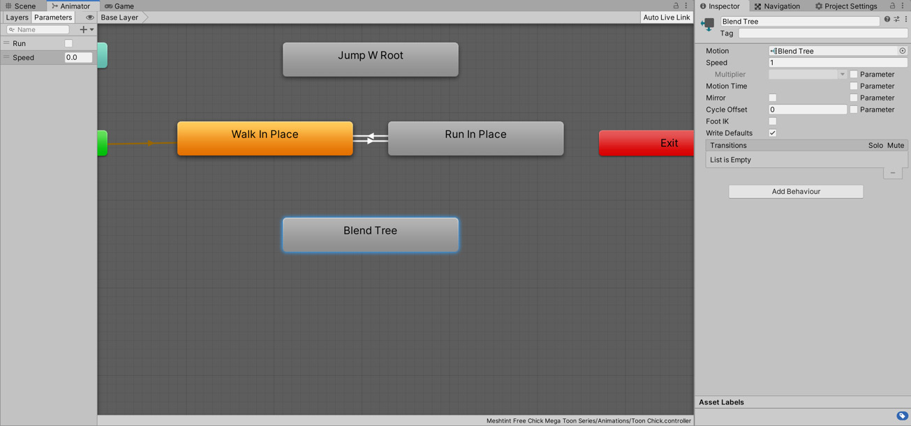
Figure 8.30 - Creating a Blend Tree
To edit the newly created Blend Tree, follow these steps:
- Double-click the Blend Tree state. This will change the view from the Layer view to the Blend Tree view, as shown in Figure 8.31:
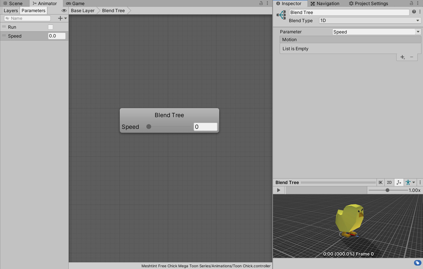
Figure 8.31 - Blend Tree view
- Select the Blend Tree. This will allow you to change the settings in the Inspector.
Tip
The breadcrumb at the upper-left corner shows that we're working on the Blend Tree. You can click on Base Layer to exit the Blend Tree.
- The Blend Type is the number of parameters used to control how each of its animations should be played. Leave this as the default setting of 1D to use a single parameter to control the motions.
- For the parameter, set Speed. Depending on the value of Speed, either the walk animation, run animation, or a mixture of the two will play.
- Select the + button under the Motion heading.
- In the menu that appears, select Add Motion Field. Each motion field can represent an animation or another Blend Tree:
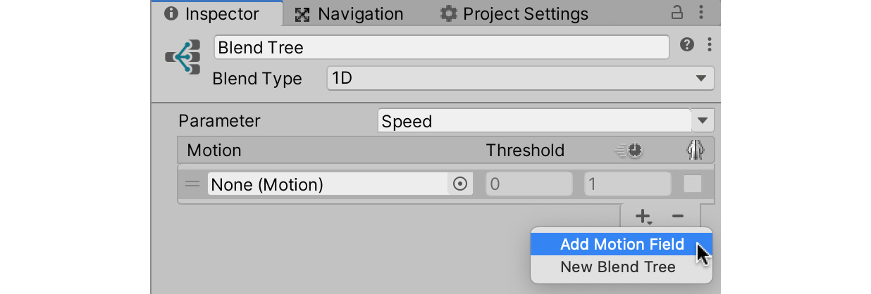
Figure 8.32 - Adding a Motion Field
Each motion field has three properties:
The threshold value represents the value of the Speed parameter required for that particular animation to have full influence.
Time Scale is the speed at which the animation plays.
Mirrored defines whether the animation is mirrored left to right.
- Drag the Walk In Place animation from the Project panel to the Motion field.
- Add another Motion field but this time drag the Run In Place animation to the Motion field, as shown in Figure 8.33:
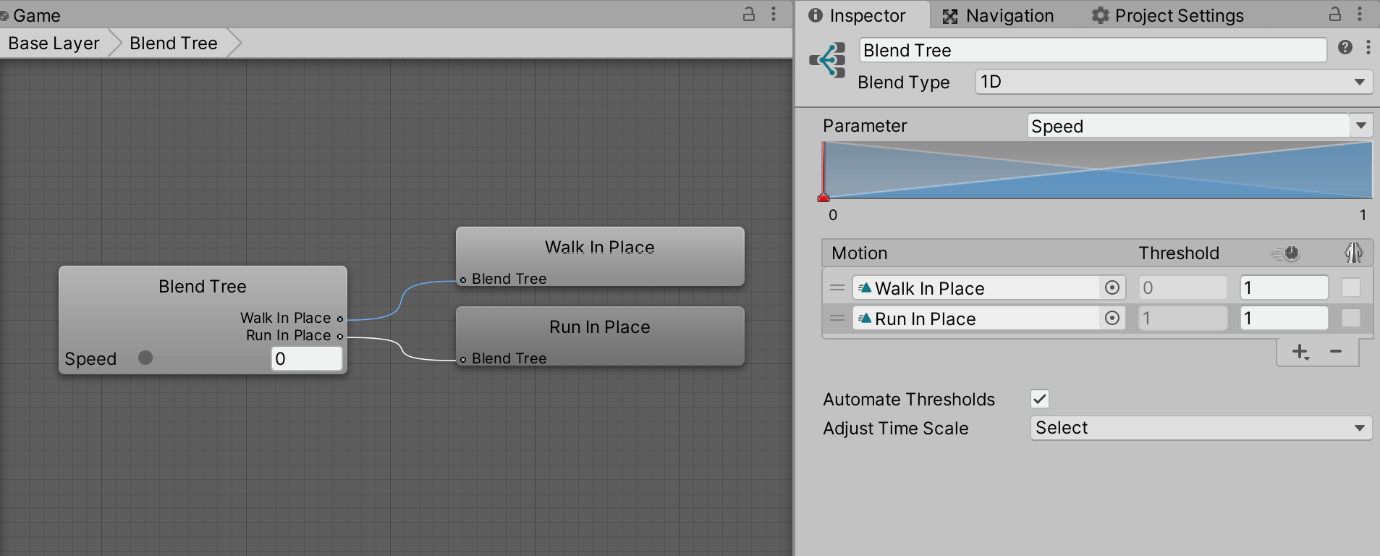
Figure 8.33 - Adding the walk and run animation
After adding the motion fields, you'll notice that a diagram appears above the list, as shown in Figure 8.33. This diagram is a visual representation of where the different animations lie on the scale of the Speed parameter— lowest on the left, highest on the right. You can drag the red scrubber, shown in Figure 8.34, to preview the animation for various values. The preview is shown at the bottom of the Inspector panel:
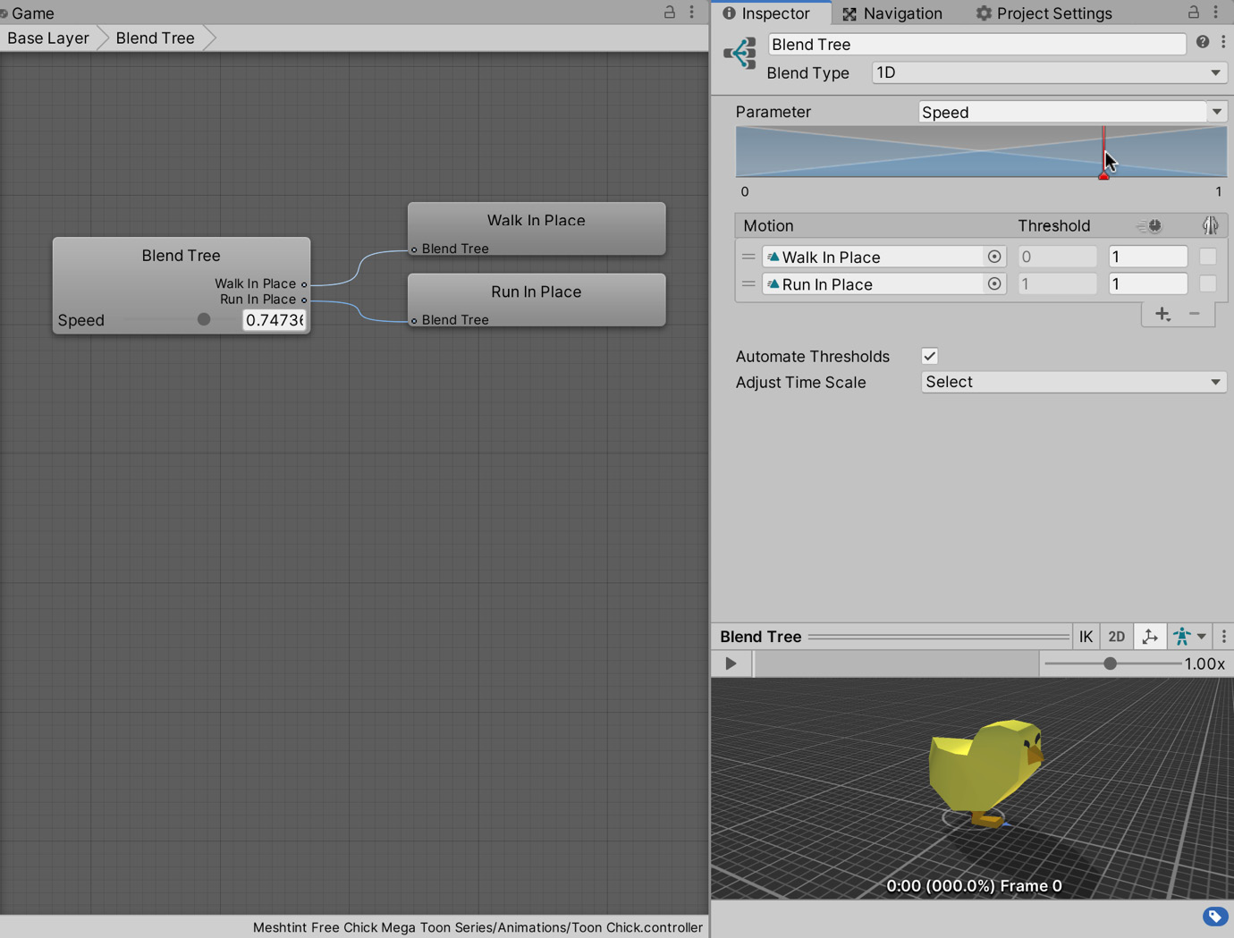
Figure 8.34 - Previewing the animation blend
If you untick Automate Thresholds in the Inspector, it will give you an additional option: Compute Thresholds. Compute Thresholds will calculate and set values for each of your motion fields. It will do this based on a property of root motion that you select; the options include the Speed parameter that we created earlier and other pre-built options including Velocity (on all three axes) and Angular speed (in radians and degrees).
Tip
When adding the motions, they were also added to the Blend Tree panel. You can click on the animations in that panel to see read-only information about the animation, including length and whether the animation is looped.
Underneath the Automate Thresholds option, there is the option to Adjust Time Scale. Using this option, you can make the speed for each animation Homogeneous, which means that each of the animations will result in the same speed of root motion. This option is only available if all of the motions are animations, not other Blend Trees.
Tip
2D Blend Trees work in a very similar way to 1D trees but blend on two dimensions.
Next, we need to set the newly created Blend Tree as the default state:
- Ensure the Automate Thresholds box is ticked. We'll let Unity calculate the threshold values for us.
- In the breadcrumb at the top of the Animator panel, click on the Base Layer to return to our animation state overview:

Figure 8.35 - Navigating back to the Base Layer
- Right-click on the Blend Tree you created.
- Select Set as Layer Default State. As explained in the previous section, this means the chick's animation will move to this state at the start of the game:
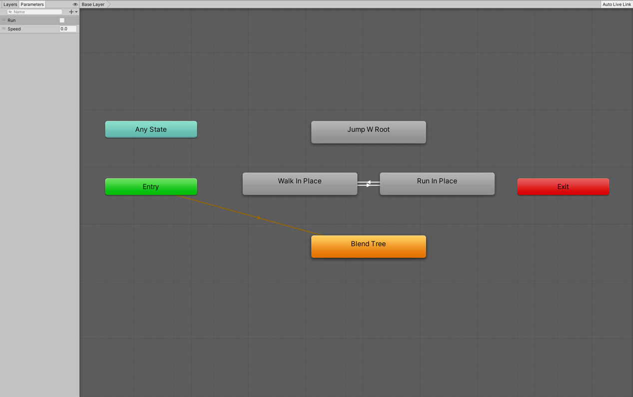
Figure 8.36 - Setting the Blend Tree as the default layer
The last step is to set the Speed parameter based on the chick's movement speed:
- Open the AnimationController class that we created in the Creating animation state section.
- Add the following:
public class AnimationController : MonoBehaviour
{
...
public string AnimationSpeedParamName = "Speed";
private float MaxSpeed;
void Awake()
{
...
MaxSpeed = ThisNavMeshAgent.speed;
}
void Update()
{
...
ThisAnimator.SetFloat(AnimationSpeedParamName, ThisNavMeshAgent.velocity.magnitude / MaxSpeed);
}
}
This code is very similar to what we wrote in the previous section to update the Run animation parameter, with the small change that we're no longer updating a Boolean but a float value instead. We divide the agent's velocity magnitude by MaxSpeed (obtained from the NavMeshAgent component) to get a normalized value between 0 and 1.
As this script is already attached to the Toon Chick object, there are no further steps required. Press the Play button to see the new blended animation in action.
That's it for the whistle-stop tour through Blend Trees. Remember that the rest of this chapter will use the animation states we created in the previous section. If you would like to do the same, you can reset the animations by doing the following:
- Select the Toon Chick in the Hierarchy.
- In the Animator panel, right-click the Walk In Place animation.
- Select Set as Layer Default State.
We've now looked at two methods of adding animations to the chick. In the next section, we'll take a look at how animations can be used for a different purpose, namely, creating a waypoint system for the chick to follow because there's no point in having created walking and running animations if the chick doesn't move anywhere!
Patrolling the environment
We now have an animated NPC that follows a destination object using Unity's built-in pathfinding and steering behavior. This functionality is a solid foundation for creating the next component in our terrifying chicks' behavioral repertoire: the ability to patrol a specified area.
If you break down a patrol, it's just moving from one destination to another in a sequence. We have most of that functionality already. We only need to implement a sequence of destinations. Multiple approaches could be taken to achieve this. One method is through scripting. We could write a script that maintains an array of different waypoint objects and allows the chick to iterate through them on a loop so that when the NPC reaches one destination, they'll move on to the next one. This approach can be very efficient and is easily customizable, but there's also another method we could use. Instead of using a script, we can create an animation to move a single destination object to different waypoint locations over time. As the NPC continually follows the destination wherever it moves, it will continuously patrol.
We'll take the second approach here for several reasons, one of the most crucial being that while we've recently examined Unity's Animator flow, we haven't yet created custom animations using Unity's Animation system:
- Start by opening the Animation window by selecting Window | Animation | Animation from the Application menu.
- Dock the Animation window into a horizontal view next to the Project panel for ease of viewing:

Figure 8.37 - The Animation window docked
- Select the object to animate (the Destination object) from the Hierarchy panel.
- From the Animation window, click on the Create button, as shown in Figure 8.37.
- From here, you will be asked to name and save the animation. I've called the animation DestPatrol and saved it to the Animations folder (create the folder as a subfolder of the Assets folder if it doesn't already exist):
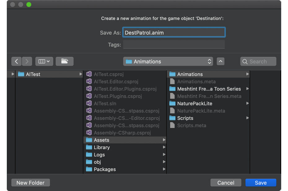
Figure 8.38 - Creating a new animation
- With the animation created, you can proceed to define animation properties. For the destination object, we'll need to add a property for the position field as the object should change position around the scene. Click on the Add Property button from the Animation window, and then choose Transform | Position as shown in Figure 8.39 to add a new position property.
Important note
A keyframe marks a transitional point. As you will see shortly, the intermediate points between keyframes are interpolated between these points to create a smooth animation.
Adding a property will automatically create starting and ending keyframes in the timeline, which are identical and hold the object's current position:
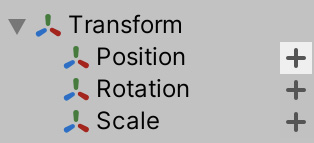
Figure 8.39 - Adding an animation property
- Click and drag the vertical slider across the timeline in the Animation window to the 0:20 mark.
- Click on the Record button. The timeline and any relevant fields on the object (in our case, the object's Position value) will then turn red. Unity will now record the position of the object to use as a keyframe:

Figure 8.40 - Recording a new keyframe
- Move the Destination object in the Scene tab to the position of the second patrol point (the first point is where the Destination object currently sits). When you do this, Unity records the object position for that keyframe. Wherever a keyframe has been recorded, Unity will add a diamond shape to the timeline and to any property that's been changed:

Figure 8.41 - Recording mode activated and new keyframe recorded
- Repeat this process for the 0:40 mark by pressing the record button and moving the Destination object to a different position.
This completes the patrol animation with three patrol points. We leave the start and end of the animation with the same position to create a loop.
You can scrub through the timeline or press Play in the Animation panel to watch the Destination object move in the Scene view to test your patrol route. The animation will most likely playback too fast as we've only set 20 seconds between each waypoint. Don't worry, that will be easy to fix as we'll see shortly. However, you may have also noticed that the destination object position has been tweened between keyframes. The Unity animation interpolates between the keyframes in the timeline causing the destination object to move smoothly between waypoints. For an animation like this, however, we want the destination to snap between the waypoints immediately without any transition. To achieve this, we need to adjust the interpolation mode of the animation curves:
- Click on the Curves button at the bottom-left corner of the Animation window. By default, the Animation window is in the DopeSheet mode, which enables us to see keyframes easily and reposition them. The Curve mode, however, lets us adjust the interpolation between keyframes:
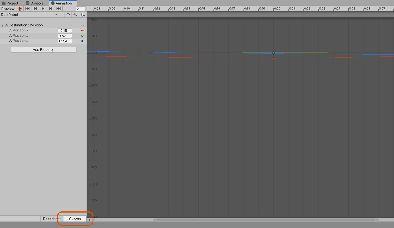
Figure 8.42 - Accessing Animation Curves
- Click and drag a selection box across all keyframes (diamond shapes) in the graph view to select them all.
- Right-click on any keyframe to display the keyframe context menu.
- From the context menu, choose Right Tangent | Constant to change all handles to a constant flat shape.
Important note
A point has a left and right tangent. Editing the left tangent changes the incoming curve to the left of the position, and changing the right tangent changes the outgoing curve to the right of the point.
The flat shape shown in Figure 8.43 signifies that all frames retain their values until the next keyframe, removing inter-frame interpolation:

Figure 8.43 - Changing keyframe handles for interpolation
Test whether the change has taken effect by pressing Play on the toolbar. When you do this, the Destination object should jump between waypoints as the animation progresses, and the NPC will try to move toward the destination. Due to the default speed of the animation, the NPC may seem a bit confused as they can never quite reach the rapidly changing destinations. To fix this, follow these steps:
- Select the Destination object from the Hierarchy panel.
- From the Inspector, double-click on the Controller field of the Animator component to open the animation graph attached to the object, which, as we've seen, controls when and how animations should play:

Figure 8.44 - The Animator panel
In the Animator window, the default node is highlighted in orange. As a reminder, the default node defines which animation (if any) will play when the object is added to the scene, which for our Destination object is on level startup. As you can see from Figure 8.44, the default node for our object is the DestPatrol node, which plays the DestPatrol animation.
- Select the DestPatrol node in the graph.
- Reduce its Speed in the Inspector. In my case, I've used a value of 0.014, which works well. You may need to test different values before you land on one that works well for you:

Figure 8.45 - Reducing the animation speed
- With speed reduced, replay your game to observe the effect.
The chick should now move between destinations at a believable speed, moving from one waypoint to the next. If the NPC moves too fast or too slow between waypoints, increase or decrease the animation speed to get the result you need. You may also need to change NPC's steering speed on its NavMeshAgent component:

Figure 8.46 - The waypoint system in action
Congratulations! You now have a complete, animated waypoint system. The chick will happily patrol between points. At the moment, it can be quite challenging to get a close up of the chick in action as you need to catch them in the Scene view. We'll change this now by adding a controllable player to the scene.
Entering the world
In previous projects, we've relied on a first-person controller included with the Unity standard assets package. In this section, instead of relying on that package, we'll write our own functionality to accomplish the same task. We'll write a script to control the player's movement through the environment and another to control where the player looks. However, before we write the scripts, we'll create the required player object:
- Create an empty GameObject.
- Name the new object as Body.
- To include the player object in the physics system and prevent them from falling through the floor, add a Rigidbody and Capsule Collider component.
- Set the Height of the collider to 2 to better represent the height of the player.
- On the Rigidbody component, Freeze Rotation on the X, Y, and Z axes. Freezing the rotation on all axes will prevent the player from falling over as they collide with the environment. We will shortly write scripts that will manually rotate the player based on user input:
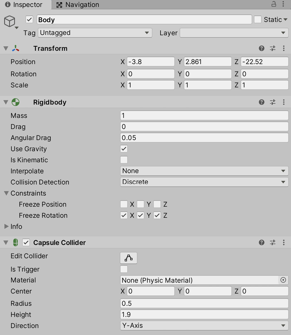
Figure 8.47 - Components attached to the Body object
- Drag the Main Camera to the Body object to make it a child object.
- The camera will act as the eyes and ears of the player; consequently, rename Main Camera to Head.
- Reposition the Head object to 0, 0.6, 0, so that it resides at the top of the Body's collider, as shown in Figure 8.48:

Figure 8.48 - Camera position as a child of the Body object
That's all the setup required for the GameObject. Next, we will script the movement:
- Create a new script called PlayerController:
public class PlayerController : MonoBehaviour
{
public float MovementSpeed = 3f;
void Update()
{
float horiz = Input.GetAxis("Horizontal");
float vert = Input.GetAxis("Vertical");
Vector3 translation = new Vector3(horiz, 0, vert);
translation *= MovementSpeed * Time.deltaTime;
transform.Translate(translation);
}
}
The following points summarize the code:
- The Horizontal and Vertical axes are queried using Input.GetAxis. This was covered in depth in Chapter 3, Creating a Space Shooter.
- A new translation vector is created using the results returned.
- The translation vector is scaled by the MovementSpeed multiplied by Time.deltaTime to create a translation vector for this frame. More information on framerate independent movement can be found in Chapter 2, Creating a Collection Game.
- Finally, the scaled translation vector is added to our current position using transform.Translate. Translate can accept a second parameter of type Space. Space is an enum with two possible values, either World of Self. As we haven't passed in a value, it defaults to Space.Self. This means that the translation is applied relative to the transform's local axis. As we'll be adding this script to a GameObject with no parents, it doesn't matter if we use the World or Self space here. However, it's something to bear in mind: if we were to add the player object as a child of another object, we may need to pass Space.World here to achieve the correct result. For a hands-on example of the Self versus World space, see https://docs.unity3d.com/ScriptReference/Space.Self.html.
- Attach the script to the Body object.
- Although we are not finished yet, you should test our current progress by pressing the Play button. You should be able to move the character around the environment using the W, A, S, D, or arrow keys.
You'll quickly notice that while we can move around, we still can't rotate the camera to look around the environment. We'll fix this now by creating another script:
- Create a new script called CameraLook:
public class CameraLook : MonoBehaviour
{
public float LookSpeed = 3f;
public Transform Body;
public Camera LookCamera;
private Vector2 Rotation = Vector2.zero;
void Update()
{
Rotation.y += Input.GetAxis("Mouse X");
Rotation.x -= Input.GetAxis("Mouse Y");
Vector2 RotThisStep = Rotation * LookSpeed;
Body.eulerAngles = new Vector2(0, RotThisStep.y);
LookCamera.transform.localRotation = Quaternion.Euler(RotThisStep.x, 0, 0);
}
}
The following points summarize the code sample:
Rotation values are retrieved by calling Input.GetAxis in the Update function.
The Mouse Y axis is subtracted from the current X rotation as the X axis controls horizontal rotation.
The Mouse X axis is added to the Y rotation, which controls vertical rotation.
The Body transform is rotated left and right, and the LookCamera is rotated up and down based on mouse movement.
The Body transform is rotated left and right instead of the camera to replicate traditional first-person controls so that the camera is always facing the forward direction. If we rotated the camera instead of the body, for example, we would end up not facing in the forward direction, so pressing forward could move you backward.
Important note
A new script was created instead of extending the functionality of the PlayerController script to help create modular, re-usable, logical units. Separating the functionality in this manner will enable us to re-use either script without having to use the other. For example, we may have a stationary turret that we want the player to control, so we add the MouseLook script without the PlayerController script.
- Attach the script to the Body object.
- Drag the Body object from the Hierarchy to the Body field on the Camera Look script.
- Drag the Head object from the Hierarchy to the Look Camera field:

Figure 8.49 - Camera Look settings
Once again, test the game and you will now be able to move freely through the environment. See if you can find the chick, as shown in Figure 8.50:

Figure 8.50 - Walking around the environment to find the chick
While this is only the basic moving functionality, it is adequate for our needs and can be extended for future projects.
Summary
Great work! We've now completed the first part of the AI project: constructing a terrain, generating a navigation mesh, and creating a basic waypoint system that an animated chick follows. We hit the ground running by importing 3D models for the terrain and NPC but also extended ourselves by writing a custom first-person controller instead of relying on the controller from the previous chapters.
This is an excellent beginning to simulating intelligence. However, as the project currently stands, there is no way for the chick to decide which action to take at any given moment; it is stuck patrolling in perpetuity. We'll fix this in the next chapter by constructing an FSM with distinct Patrol, Chase, and Attack states. We'll also look at how we can test to see whether the player is in the chick's line of sight using Raycasting. This check will act as a condition to transition between specific states, just as we used the Run parameter as a condition to switch between animation states in this chapter.
Test your knowledge
Q1. You can generate a walkable surface of the level for AI by using...
A. Pathfinding
B. A Collision Box
C. Navigation Mesh
D. A Path Tree
Q2. The Animator window of Mechanim is useful for...
A. Controlling when and how animations play
B. Creating loopable animations
C. Editing characters
D. Applying inverse kinematics
Q3. To walk on a Navigation Mesh, an object needs...
A. Pathfinding
B. A Collision Box
C. A NavMesh agent component
D. A Collider component
Q4. You can edit animation interpolation by changing...
A. High poly meshes
B. Keyframe curves
C. Box Colliders
D. Mesh renderer components
Q5. The blue local axis arrow of an object is known as...
A. Forward vector
B. Right vector
C. Up vector
D. Pitch
Further reading
Check out the following links for more information on animations and pathfinding:
- https://docs.unity3d.com/Manual/Navigation.html
- https://www.packtpub.com/game-development/unity-2018-artificial-intelligence-cookbook-second-edition
- https://www.packtpub.com/game-development/unity-animation-essentials
- https://docs.unity3d.com/Manual/StaticObjects.html
- https://docs.unity3d.com/Manual/nav-BuildingNavMesh.html
- https://docs.unity3d.com/Manual/AnimatorWindow.html
- https://docs.unity3d.com/Manual/AnimationLayers.html