
Chapter 18. Intermediate Blueprints: UMG Interaction
Building a User Interface is a challenge that most visualization professionals have likely never tackled before. Without the right tools, this can be a daunting task. UE4 introduces UMG (Unreal Motion Graphics), a complete user interface solution that can be used to develop complex, data-driven interfaces or simple toggle buttons and logo overlays that are essential for producing a polished and easy to use interactive visualization.
Toggling Datasets
The next stated goal in this project is to allow the Player to switch to an alternative variation of your Level while maintaining a single camera position. This in-context switching is one of the most powerful features of interactive visualizations. Enabling the Player to compare different data from the same view is a great way to analyze alternatives and, allowing that Player to choose where to place the camera is extremely empowering.
UE4 features a system called Level Streaming that is designed to load and unload entire Levels at runtime. This was developed to allow games to have very large Levels, broken up into sections that are loaded and unloaded as the player moves through them without loading screens interrupting the flow of the game.
In this chapter you learn to use this system to load up two versions of your map simultaneously and hide and unhide them, first using a simply keyboard toggle for testing, and then by authoring a UMG UI for players to use.
To do this, you must first develop a new Level based on your new data, complete with Lighting, Materials, and Props. You’ll use your existing Level as a base, reusing much of your work from the previous chapters, saving a lot of development time.
After you have that you will create a UMG (Unreal Motion Graphics)-based user interface that lets the Player simply click buttons to instantly switch between the different variations. You will learn how to create a UMG Widget Blueprint and attach it to the Viewport and how it takes user input and issues commands to modify the game world.
Making the Variation Level
You have been provided an alternative layout of your space by the client. This one has a dramatic, lofted area over the living room (see Figure 18.1).
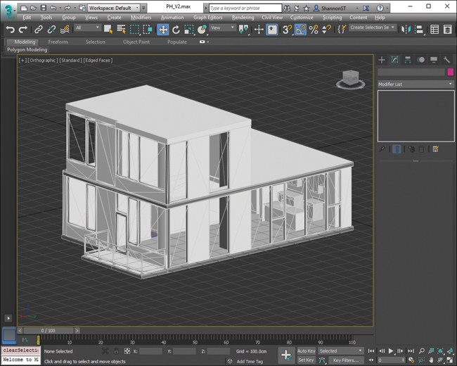
This change is significant and will affect the look, feel, and lighting of the Level so much your best bet is to create an entirely new Level, complete with its own lighting and geometry.
Luckily you don’t have to do that from scratch. You can use your existing Level as a starting point. First, load up your Level in the Editor if it’s not already. You can load Levels by going to File > Open Level or by finding the UMAP Asset in the Content Browser and double-clicking on it.
Making a Copy with Save As
Create a copy of the Level by choosing File > Save Current As and then name it something descriptive like Example2_V2_MAP.
This gives you two Levels in your project: Example2_MAP and Example2_V2_MAP.
At this point the Levels are exactly the same apart from the name.
Importing the New Architecture
Because your Levels share so much in common, including the prop placement, lighting, and other details, you will only need to replace the Architecture Meshes. You can also choose to replace only the Meshes that are changing, but for the sake of this example, let’s create a fully unique Level with fully unique geometry.
As in Chapter 12, “Data Pipeline,” prepare your content in your 3D application. Apply UVW mapping, check for poor geometry, and organize your content as you have before. You should come up with a new naming variation for these Meshes to avoid potential conflicts.
After it’s prepared, export to FBX and import into UE4.
When you import your FBX files into UE4, you should put your content into a new folder apart from the previous Architecture Meshes; this ensures the two datasets are maintained separately, avoiding data conflicts.
As before, import your FBX files into the Content Browser using the suggested settings for Static Architecture Meshes—most importantly, ensuring Auto Generate Collision is set to false, Generate Lightmap UVs is set to true, and Transform Vertex to Absolute is set to true as well (refer to Figure 12.5 in Chapter 12).
After importing the FBX files, don’t forget to save the Static Mesh Assets you just created before moving on.
Replacing the Architecture Meshes
In your new Level (Example2_V2_MAP), select all the Architecture Static Mesh Actors in your scene. Press the Del key or right-click on the Actors and select Delete to delete them, leaving only the Props, Lights, and other Actors.
To place your new Architecture Meshes, drag them into the Viewport, and then reset their position to 0,0,0 using the Location property in the Details Panel. You should now have updated Architecture.
While your recently placed Static Mesh Actors are still selected, it’s a good time to also organize them into a folder in your World Outliner so you can easily select them in the future.
Setting Up Lightmap Density
Now that you’ve replaced the walls, floors, and ceilings, they have returned to their default Lightmap resolution. You must go through and modify your newly placed Meshes’ Overridden Light Map Res property, using the Lightmap Density Optimization View Mode.
You should try to match the density you set up in the previous map as much as possible. This ensures the lighting builds look consistent between the two Levels.
Applying Materials
Your newly imported Meshes will undoubtedly be either lacking Materials or have the default, imported Materials applied. Take the time to apply the materials as applied in the first Level.
Enabling Collision
The last thing you need to do is ensure your Collision is set up correctly. Use the Player Collision View Mode to determine what Meshes need to have Collision enabled.
Decorating (Optional)
You can take this opportunity to make as many changes as you want to the Level—try some different Lighting, Materials, Props, you name it. In this example, the Props, Lighting, and Materials are left the same, leaving the only change to be the architecture. This allows the Player to focus on the differences being distracted by any other changes.
Building Lighting
Lighting is stored on a per-Level basis. So, you can have the same Assets in different Levels with vastly different lighting setups and Lightmaps. This allows you to bake lighting on a per-Level basis while using all the same Asset references.
An advantage of using the Save As method for creating a new Level is that it retains all the World Settings you applied earlier, including the Lightmass settings. This makes building lighting very easy indeed; you should simply be able to set your Lighting Build Quality to the Level you want and click the Build button.
After building the lighting, you should have a new variation of your Level with awesome vaulted ceilings and the lighting changes that provides (see Figure 18.2).

Save your Level. The Light and Shadow maps will be written to the Level (or as of version 4.15, to a separate Build Data file alongside the Level that is only visible in the Content Browser or File Explorer).
Level Streaming
UE4 can load and unload entire Levels on the fly. This is called Level Streaming and the system can be used to easily swap large datasets in and out using simple Blueprint commands.
The way Level Streaming works is fairly simple. A single Level, called the Persistent Level, is first loaded. This Level is often very simple or even almost completely blank.
This Level, or an Object or Actor within it (a Blueprint or the Player Controller, for example) can load another Level or Levels into or out of it. You can also toggle the visibility of the loaded Levels both in the Editor and at runtime, making for a convenient way to switch datasets quickly.
To set up your Level Streaming, you first make a Persistent Level, then add your two versions as Streaming Levels using the Levels interface (see Figure 18.3).

Making a New Level
Let’s first make a new, blank Level for your Persistent Level. Choose File > New Level and select Empty Level from the options available.
When your new, blank Level is open, save it and name it (for example, Example2_Persistent_MAP). This map contains only some Blueprint code in the Level Blueprint to handle the toggling of your streaming Levels.
Accessing the Levels Interface
The Editor exposes the Level Streaming system through the Levels list. You can access it by choosing Window > Level. This opens the Levels window (see Figure 18.3).
You will see the currently loaded Level listed as the Persistent Level.
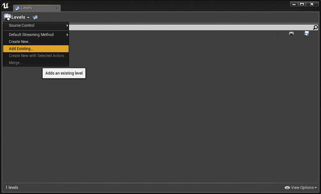
Adding Streaming Levels
Click the Levels button in the upper-left corner of the Levels window and select Add Existing from the dropdown menu. Select the original Level (Example2 _MAP) you made (see Figure 18.4). You can also create a new, blank streaming map, or create a new map with the selected Actors.
The map loads into the Viewport and you see it listed in the Levels window.
Do this again to add the new version (Example2 _V2_MAP) into the Levels window.
You should now see both Levels in the Levels window as well as in the Viewport.
You can hide and unhide Levels using the Eye icon on each Level. You can also save Levels, open their Level Blueprints, and toggle an editing lock to prevent changes. Even if your project isn’t using Level Streaming at runtime, using them can be a great way to split up a big scene into smaller files or to organize things (see Figure 18.5). Note in the figure that Example2_MAP is hidden using the Eye icon that now displays as a closed Eye icon.

Remember that the view toggles set for each Level in the Levels window are Editor-only and that Level visibility at runtime is handled through Blueprint logic.
You now need to save your Persistent Level because you have modified it by adding the Streaming Levels using the Levels interface.
Using Blueprints Versus Always Loaded Levels
Notice the small blue dot next to your two new Levels in the Levels window. This means that the Levels are loaded using Blueprints, and that they will not load until you tell them to using Blueprints. You can also unload and hide and unhide these Levels at runtime.1
1. Unloading and loading Levels removes them from memory and can take some time to happen at runtime. Hiding and unhiding keeps the Level loaded but simply toggles rendering of that Level’s content. This happens instantly.
Alternatively, you can set Levels to be Always Loaded. As the name implies, these Levels are always loaded and cannot be hidden or unloaded at runtime.
Levels that need to always be loaded can be set this way by right-clicking on the Level in the Levels window and choosing Change Streaming Method > Always Loaded. These Levels will load as if they were part of the Persistent Level when the game is played.
Keep your Levels’ Streaming Method as Blueprints because you want to be able to hide and unhide them at runtime using Blueprints.
Defining a Player Start Actor
Even though your two Streaming Levels have Player Start Actors already in them, you need to define one for your new Persistent Level. This can sometimes be a little confusing because you can clearly see the Player Start Actors and select them in the Editor Viewport, but they will not be there when the Level initially loads. This is because the Player Controller is spawned before the Streaming Level has a chance to load.
You can easily copy and paste one of your Player Start Actors from one of your Streaming Levels into the Persistent Level Select the Player Start from the Content Browser or the Viewport and then go to Edit > Copy or choose Edit > Copy from the right-click menu.
Pasting requires a little more care. When you have multiple Levels loaded in the Editor, you need to define what Level is your active Level before pasting the Player Start.
You want this Player Start to be placed in the Persistent Level, so double-click on the Persistent Level in the Levels window to make it active. You can tell it’s the active layer because the name will turn blue.
Paste the Player Start Actor into the Persistent Level using the Edit menu, the right-click menu, or simply using Crtl/Cmd+V.
You could also just place a Player Start using the Class Browser as you did before, but you would still need to ensure the right Level is active.
Now you have a Player Start placed in your Persistent Level. However, if you click Play now, you’ll still just load into a black, empty world. You need to set up the Level Blueprint to load streaming Levels.
Setting Up the Level Blueprint
Now that your streaming Levels are set up in the Editor, you can write the Blueprint logic to get them to switch using the Level Blueprint.
Opening the Level Blueprint
Each Level has its own Blueprint Event Graph called the Level Blueprint. This Blueprint is a great way to do Level-specific actions; things that would only happen in a single Level based on specific Actors or Events in that Level. An example might be the Player triggering a door to open or setting specific music to play when a Level opens.
Any functionality that needs to be common from Level to Level (player movement, for example) should be handled by a regular Blueprint Class, because you wouldn’t want to have to duplicate and maintain that code for each Level you make.2
2. At runtime, all your Levels are loaded into a single world and everything can access everything else. However, in the Editor, Actors and Levels can only access other Actors with the same Level.
To access the Level Blueprint you can either click on the Gamepad icon in the Levels window that corresponds to the Level you want to edit or click the Blueprints button from the Editor toolbar and select Open Level Blueprint (see Figure 18.6).

You can also access the Level Blueprints of the loaded Levels and get quick access to your Game Mode’s Classes.
Note
Streaming Levels can have their own Level Blueprints. This is because a Level Blueprint can only reference the Actors that are in its own Level.
The Level Blueprint opens in the Blueprint Editor window (see Figure 18.7). This Editor is a little different than the Blueprint Editors you have used so far. This one notably lacks the Viewport, Components, and Construction Script tabs Level Blueprints only have the Event Graph because they cannot have Components and do not undergo construction like Actor Classes do.

Using Events
An Event is a special node that is called from gameplay code. When called it fires the node graph wired to its output execution pin (the white arrow). These Events can be called in response to a variety of gameplay Events such as the game beginning, the Level being reset, or a player pressing a specific input.
UE4 has many pre-existing Events. Two of the most common are visible in Figure 18.7 above: BeginPlay and Tick. Also remember that you used InputAxis Events previously to set up input in your Player Controller.
BeginPlay
The BeginPlay Event is called automatically by the game one time when the Level is first loaded after all the Actors and world objects have been loaded and initialized.
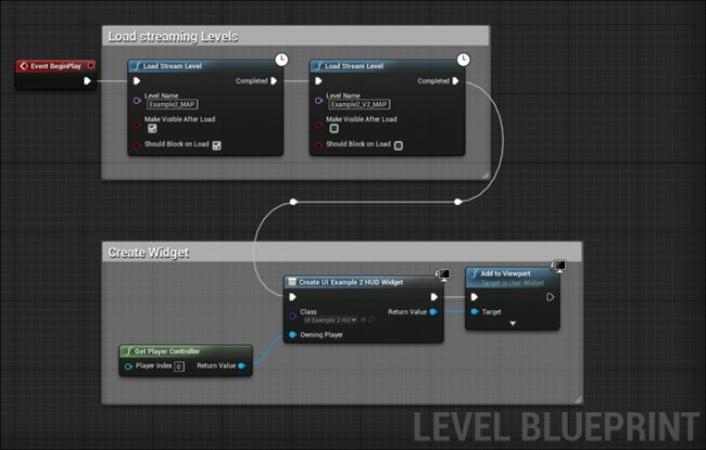
This is where you set up your initial Level Streaming code. As mentioned, your Persistent Level is empty and needs to have the Levels streamed in.
To do so, you use the Load Stream Level function. You can see in Figure 18.8 that I have placed two of these nodes. Like with most nodes, right-click in the Event Graph and search for the Load Stream Level node.
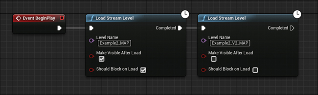
After placing both nodes, you need to fill in the settings on each to match Figure 18.8. Example2_MAP is loaded first using the Load Stream Level node with Should Block on Load and Make Visible After Load is set to True. Example2_V2_MAP is then loaded but is set to be hidden initially by setting the Make Visible After Load parameter to False.
You must set the Level Name property to the exact name of the Level in your Levels window. Also, you must have the Level loaded as a Streaming Level in the Levels window to be available to stream through Blueprints.
Should Block on Load forces UE4 to wait for the first Level to load before continuing to run any game code (this is what a “block” is—it blocks the game from continuing). Blocking prevents your Pawn from falling through the empty void of your Persistent Level before the Streaming Level and its associated collision are loaded.
Note
Loading multiple streaming Levels at the same time can be extremely memory intensive. If you are running into crashes or poor performance, try to reduce your memory overhead, especially your video card VRAM. Start by reducing the resolution of your Reflection Capture Actors and/or reduce the resolution of your Lightmaps.
Latent Functions
Notice the Clock icon on the Load Stream Level functions. This indicates that this node is a Latent function. Latent functions take time to complete and only continue the flow of the event graph when their task is completed.
Loading Levels can take several seconds. Larger Levels and slower hard drives can increase this time. This can cause a hitch in your application while they’re loading. This is why we’ve chosen to load them once at the same time, at the initial load of the Persistent Level, and toggle their visibility. By keeping them both in memory and simply changing their visibility, we can avoid this hitch and switching is almost instantaneous.
Testing Time
If you click Play now, your application should load the map almost exactly as before. However, it probably took a little longer than when you’ve tested with PIE before.
This is because you are waiting for the Levels to stream in; even the V2 map that isn’t being shown yet takes time to load.
After the Levels load, however, you should be able to move about the space like you did in the previous chapter, but this time, you’re doing it with fancy Level Streaming.
Programming the Switching
Now that you have the maps loading, let’s get them toggling. With only a few nodes in your Level Blueprint, you can accomplish this. You will also see how to create an easy keyboard shortcut to test your Level switching before you tackle developing the UMG interface.
Creating Custom Events
You can create your own Custom Event nodes that can be called at any point in your Blueprint from other Blueprints in your world, providing a way for you to organize your Event Graphs and allow Blueprints to communicate with each other.
You need a few Custom Events that can toggle the visibility of the Levels. You’ll use these Events to test the Level switching and then use the same Events later when you develop the UMG interface.
In the Persistent Level Blueprint, you create a Custom Event node by right-clicking on the Event Graph background and choosing Add Custom Event from the context menu (see Figure 18.9).
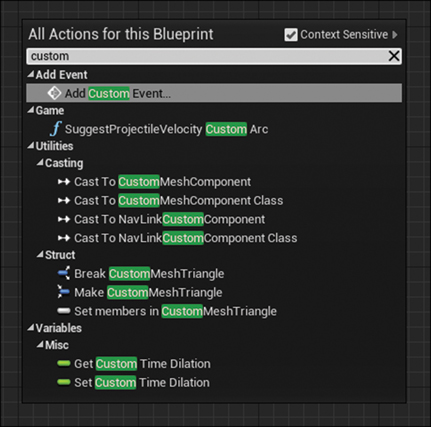
When you create an Event, give it a unique Name and press Enter to confirm.
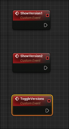
You need three Events for your switching system to work, so place three Custom Event nodes, naming the first ShowVersion1, the second ShowVersion2, and the third ToggleVersions. Your Event Graph should look like Figure 18.10.
Setting up the Show Versions Events
The Show Version 1 and Show Version 2 functions simply set the visibility of your Streaming Levels, allowing you to toggle between them.
Set up your Event Graph as shown in Figure 18.11.
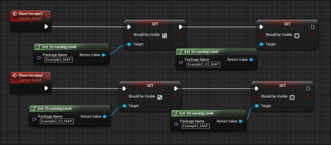
These two, almost mirror image execution graphs hide one Level while showing another. The Get Streaming Level function returns a reference to the Level defined in the Package Name property. You must manually enter this name and it must be the exact name of your streaming Levels.
To access the Set Should be Visible property of the Level, drag a wire from the blue Return Value pin of the Get Streaming Level function node into the Event Graph and release to access the contextual menu for Streaming Levels and search for Set Visible.
Set it up so you are first unhiding a Level then hiding the other. You can see the Level’s name being declared in the Package Name of the Get Streaming Level nodes.
Toggle Versions Event
The Toggle Versions Event toggles between the two variations each time it’s called (see Figure 18.12). The Flip Flop node is specifically designed for this and it’s fun to say.

The first time the Flip Flop is called, it only fires the A out execution pin. The next time, it only fires the B execution pin, then A, and so on, alternating between calling the two Custom Events you created previously.
To create a call to a Custom Event, right-click in the Event Graph and search for the name you gave your Custom Event when you created it. To ensure your Custom Events listed, you should Compile and Save your Blueprint.
Testing Time
Now that you have all this set up, take time to test before tackling the UMG interface. Without the UMG interface, how can you test your work so far? An easy way is to simply create a keyboard shortcut in the Level Blueprint.
Creating the Keyboard Shortcut
Level Blueprints can intercept Player input Events, just like the Player Controller can. You can use this to easily set up a keyboard shortcut to call out Toggle Versions Event.
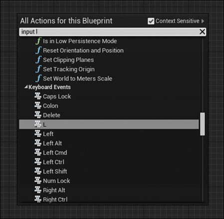
From the right-click context menu, search for “Input L” (see Figure 18.13) and select L from the Keyboard Events list.
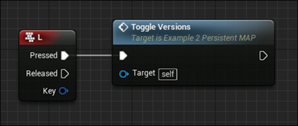
Then, simply wire a call to the ToggleVersions Event from the Pressed execution pin on the L Keyboard Input Event, as shown in Figure 18.14.
Compiling and Saving
You should now compile your Level Blueprint, ensuring there are no errors or warnings, then save the Persistent Level to save the code you’ve written.
Clicking Play
Now when you click Play, you should be able to press the L key on your keyboard and your Level will instantly toggle between your two versions.
You will notice what a dramatic change the additional windows make in the entire scene, even in hallways far away from the main modifications. This ability to switch options in-content like this is extremely powerful and gives the Player a personal experience. No two players will look in the same place and toggle the differences at the same time.
However, you can’t expect everybody to know that they can press L to make this change happen. You need to present a user interface to the Player that gives him clear options. For this you use Unreal’s built-in user interface system, UMG.
Unreal Motion Graphics (UMG)
Unreal Motion Graphics UI Designer (UMG) is a visual UI authoring tool that you can use to create in-game UI elements such as menus, titles, and buttons. UMG is hardware-accelerated, modern, and platform agnostic, meaning that it runs fast, looks great, and can be used on any platform UE4 supports. You can author a single interface for use on everything from PC and Mac to the Nintendo Switch and everything in between.
Using Widgets
UMG relies on Widgets, pre-made elements that you can use to construct your interface. Pre-built Widgets are available for most common UI elements including buttons, sliders, dropdown boxes, and text labels, along with Widgets to help organize and arrange other Widgets in the UI.
Widgets are assembled in a Widget Blueprint, a specialized Blueprint Class with a customized Editor.
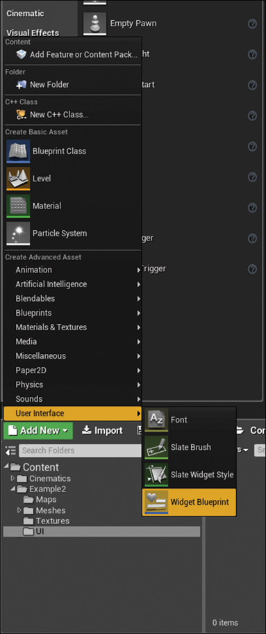
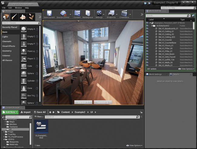
You create Widget Blueprints like most UE4 Classes, in the Content Browser. In the Add New menu, navigate to User Interface > Widget Blueprint (see Figure 18.15). Name your new Widget UI_Example2_HUD. HUD means Heads up Display and is commonly referred to as the interface that is always showing when the game is being played. Other common UI setup examples would be a main menu or a pause menu.
Now, double-click your newly created Widget Blueprint to open it for editing (see Figure 18.16).
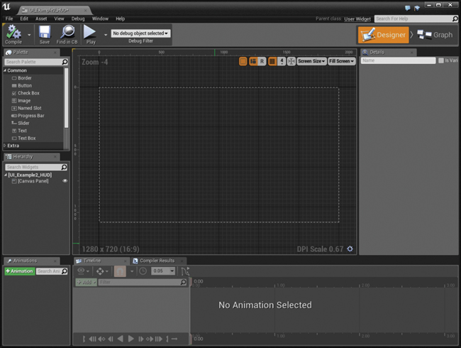
This Editor is arranged in two main sections: the Designer tab that allows you to visually set up the elements of the UI, and the Graph tab where you can add functionality to your UIs. In the upper right, you can see the Designer and Graph tabs. Click these to switch between the two interface modes. In the center is the Stage and on the left is a Palette with all the Widgets available to build your UI. Below that is the Hierarchy that shows placed Widgets in a nested list. On the bottom are the Animation List and the Timeline. You can use these to develop keyframed animations for your UI elements. Finally, on the right is the Details Panel. Like all other Details Panels in UE4, it’s contextual and displays the details of the currently selected Widget.
Horizontal Box
For this UI, you want two buttons to enable toggling between your variations. You want these buttons to be neatly arranged along the bottom of the screen with even spacing for a clean, professional look.
UE4 ships with a Widget that helps with this: the Horizontal Box Widget. This Widget can have multiple child Widgets nested within it, evenly spacing each of those Widgets horizontally.
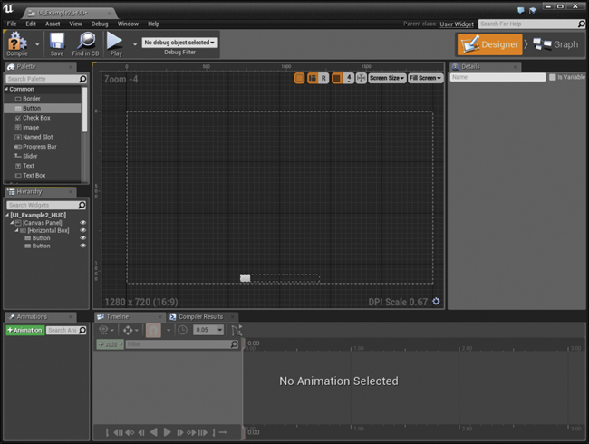
Find the Horizontal Box Widget listed in the Palette window under the Panel group. Drag it into the Stage. The Widget appears on the Stage and in the Hierarchy list.
Your Widget likely didn’t land in quite the right spot, so you need to move it to the bottom of the screen where you want it. You could simply drag it, but that’s not the best practice.
UMG supports arbitrary resolutions and scaling so that it can be used on pretty much any device with any kind of screen.
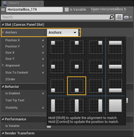
One of the ways it does this is by using Anchors for Widgets. An Anchor ensures that a Widget is always stuck to a relative part of the screen: the side, the corner, or the center.
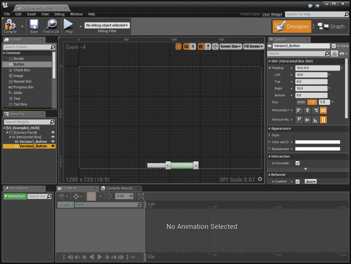
In this case stick it to the bottom center by clicking on the Anchors dropdown in the Details Panel (see Figure 18.17).
When you do this, you won’t see much change in the Viewport because UE4 tries to adjust all the layout properties so the Widget stays in the same location. You must modify those properties to get the Horizontal Box Widget where you want it and the size you want it (see Figure 18.18):

1. Set the Position X to 0 and the Position Y to –10. This centers the Widget, but leaves 10 pixels from the bottom of the screen.
2. Set the Size X to 500 and the Size Y to 50 to define the size of the box.
3. Set the Alignment. This is basically a pivot point offset. If you set it to 0,0, the Widget will transform from the upper-left corner and at 1,1 it transforms from the lower-right corner. An alignment of 0.5, 1.0 will cause the Widget pivot from the center bottom.
You should now have a box ready to organize some content, so let’s give it some content!
Buttons
Simply drag two Button Widgets from the Palette into the Horizontal Box Widget. You can do this either to the Stage or the Hierarchy window (see Figure 18.19). Dragging to the Hierarchy window can be a big help when your UI Widget becomes complicated.
You need to do some styling and setup of your buttons to get them to look and behave right.
Select the buttons one by one and set them up as follows (see Figure 18.20):
1. Most importantly, you need to provide each of your buttons a unique name. If you do not, trying to access these Widgets from Blueprints will be a challenge.
2. Set the Padding to have 10 pixels on the left and right. You might need to expand the Padding option by clicking the arrow next to it to reveal the individual padding options.
3. Set the Size to Fill and 1.0. This makes the buttons fill up whatever area available, rather than trying to be as small as possible (Auto).
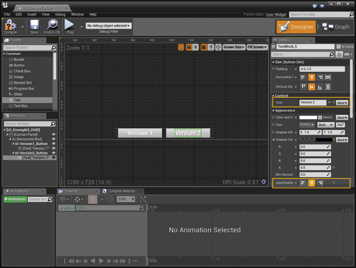
Labels
You need some labels for your buttons. Fortunately, the Button Widget Class can have a single child Class—perfect for a Text Widget to go in to act as a Label.
Find the Text Widget in the Palette and drag one into each of your buttons. Set up the Label’s Text property to read Version 1 and Version 2. You might also want to add a slight drop-shadow to the text to make it slightly more legible (see Figure 18.21).
It’s a great time to save your work if you already haven’t. Your interface is complete and you won’t need to add any code directly to the graph of this Widget Blueprint because you will handle all that in the Level Blueprint.
Back to the Level Blueprint
You have all the pieces you need to make this system work; now you just need to assemble them. You do all the final assembly back in the Level Blueprint.
Open the Level Blueprint—click on the Blueprints button in the Toolbar and select Open Level Blueprint.
The most obvious question at this point is: How do I get my UI that I just made and make it display? To do so in UE4, you attach your Widget Blueprint to the Player’s Viewport using Blueprints as shown in Figure 18.22.3
3. Notice the Redirect nodes in the white execution graph. These allow the programmer to make their node graphs more readable by defining the shape of the execution lines. To add one, double-click on a wire.
The best place to do this is the Begin Play Event because you want the HUD to display when the Level loads. You’ll add this code after your Level loading completes so you aren’t presenting the Player with the UI before he can click on it. (That’s rude!)
The following sections walk you through wiring all your components together.
Creating the Widget
The first step is to create the Widget object, which loads the widget class from disk and creates an instance of it in memory (you could, of course, create more than one of any given Widget, all instantiated from the one Widget Blueprint Class).
As usual, right-click in the Event Graph and search for Create Widget to create this node.
After placing the Create Widget node, you need to do two things:
1. Assign the Class you want to spawn; in this Case UI_Example2_HUD, by selecting the Class dropdown.
2. Provide this function with a reference to your Player Controller. Simply right-click on the Viewport, find Get Player Controller from the list, and then wire it to the Owning Player pin.
You need to do this because a multiplayer environment can have more than one Player Controller and you need to know who the HUD belongs to. In this case you only have one so you can simply just reference the first Player Controller available.
Adding the Widget to the Viewport
To get the Widget to attach to the Viewport and be seen and intractable, you need to add it to the Viewport.
To access the Add to Viewport node, drag a wire from the Return Value of the Create Widget node (that should now read “Create UI Example 2 HUD Widget”) and release into the Graph Editor, which opens the context menu for your Widget Class. Search for the Add to Viewport node and add it to the graph. The blue wire will automatically connect to the Target pin of the newly created Add to Viewport function.
Now is a good time to click the Compile button and if there are no errors, save your Level Blueprint.
If you run the game now, you’ll see your two buttons displayed at the bottom of the screen. If you click on them nothing happens. Luckily you’ve already set up the switching functions; you just need to get the buttons to call those functions when pressed.
Event Binding
A powerful feature of UE4 is the ability for one Blueprint to bind to an Event in another. This lets a single Blueprint handle multiple interactions or Events with a single, unified code path.
To detect Events, you must first get a reference to the buttons you made (see Figure 18.23). You can do this easily because the Create Widget method returns a reference to the Object it creates. So, drag a wire from the Return Value into the graph to access the context menu for your Widget Class.
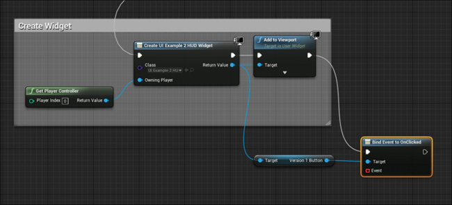
Search for Get Version and select Get Version 1 Button. From this Get node, again drag out a blue wire and search for Bind. You can bind to quite a few Events and you can also unbind Events as well. Choose Bind Event to OnClicked for your button. Wire it to the Add To Viewport function because it must get called for the Bind that you will set up to take effect.
You now need to define what Event will be called when the bound OnClicked Event is fired. You do this with the red/orange Event reference pin.
Drag from this pin to the similar pin on the ShowVersion1 Custom Event. You might need to move your nodes around so that doing this is easier (see Figure 18.24).
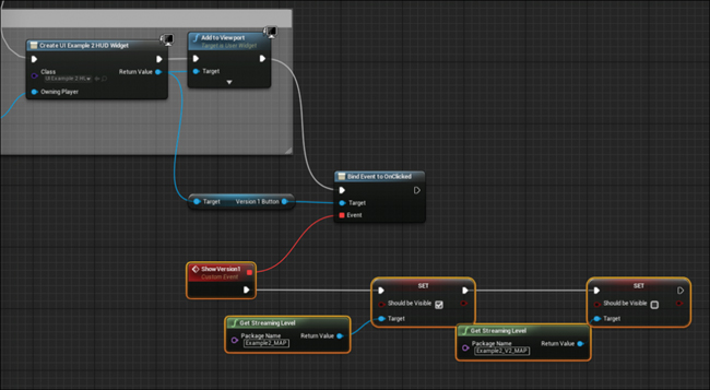
Figure 18.24 Binding your previously created ShowVersion1 Event to the OnClicked Event of the Version1Button Widget
Now, of course, repeat for the other button by getting a reference from the Create Widget node and assigning your other Custom Event to that button’s OnClicked Event (see Figure 18.25).
Now clicking the buttons causes the Events to fire, switching the Levels.
Compiling and Saving
Be sure to compile your Level Blueprint and if there are no errors, save your work.
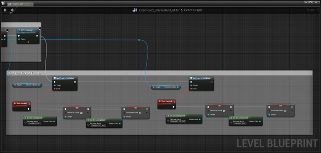
Playing the Game
You can now click Play on your Level and experience a fully fledged, mouse-driven user interface. You should be able to navigate about using the keyboard and mouse, toggling between the two versions effortlessly with the UI (see Figure 18.26).
Summary
You’ve come a long way and tackled a lot of new ground in this chapter.
You’ve learned about the Level Streaming system in UE4 and used it to easily toggle entire Levels instantly at runtime. This is a great way to swap out datasets in visualization applications and is easy to set up and maintain.
You also looked at how Blueprints can communicate with each other using Event binding and used that ability to build a simple but effective user interface with UMG.
UMG is a great resource and one of the best user interface tools available. Combined with UE4’s flexibility and power, you can create pretty much any application you can imagine.
Although this game is only a simple example, UMG has been used successfully on projects as complex as a full-blown AAA, blockbuster video game to a simple A/B comparison tool like this. Its performance, flexibility, and ease of use has made it one of the reasons UE4 is becoming such a dominant force in nearly every visual industry.