
Chapter 2. Working Around the Diagram
In this chapter, you learn how to manage and work with templates, drawing files, documents, pages, backgrounds, themes, stencils, and master shapes.
You will spend the majority of your Visio life dropping, moving, resizing, formatting, connecting, and adding text to shapes. But all that work will be easier if you understand the bits and pieces that surround the diagram and complete the Visio story.
Getting Started with a New Drawing
You can create a new Visio document in several ways. You briefly saw the template gallery and used the Basic Flowchart template in the preceding chapter. Now, take a look at templates and the various other ways to start new diagrams.
Navigating the Template Gallery
When you start a new Visio drawing, the first place to go is the Backstage area. Click File and then select New from the list on the left, and you see Visio’s template gallery, as shown in Figure 2.1.
Figure 2.1. The Home view of Visio 2010 Premium’s template gallery.

Right away, you notice the major areas of this screen. From top to bottom in the middle panel are: Recently Used Templates, Template Categories, and Other Ways to Get Started. On the right, there’s a big preview area, with a Create button underneath that screams “Click Me!”
Templates that you frequently access will appear in the Recently Used Templates at the top, but all templates can be found using Template Categories in the middle.
One thing can be a bit confusing at first. When you are at the top level, the icons in Template Categories appear blue and have a “sheet of paper” look. These icons serve as folders that contain more templates. Click one, and you drill down into the folder and see a list of templates for that category.
Figure 2.2 shows the template icons inside the Maps and Floor Plans category for Visio Premium. If you have the Standard edition, you see only three templates.
Figure 2.2. Diving into Visio 2010 Premium’s Maps and Floor Plans template category gallery.
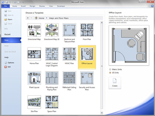
Inside a category, the blue icons and the Template Categories bar disappear. In roughly the same place, you now see larger, more-detailed, full-color icons that represent actual templates. It can take a bit of time to get used to this difference: Big, colored icons represent actual templates; smaller blue icons with document motifs represent template categories at the higher level. Take a moment to contrast Figures 2.1 and 2.2.
When you click on a template icon, the preview area shows a zoomed view of the icon, along with a description of the template. This gives you a clear idea of what you can create with the template. To start, just click the Create button or double-click the template icon itself. A new, unsaved copy of a drawing based on that template then appears in the Visio drawing window.
If the category doesn’t have the template you need, you can go back one level by clicking the Back button near the top of the page or by clicking the Home button. From there you can dive into a different category of templates.
What Happens When You Start from a Template?
When you start a drawing from a template, a few things happen:
• You get a new, “blank” document that is an unsaved copy of the original template.
• The document’s rulers, grid, measuring system, and page size are appropriate to the drawing type and unit system you’ve chosen.
• Several stencils are opened that present you with palettes of shapes for completing the drawing. Stencils are separate files in themselves but are conveniently displayed in the Shapes area in docked, stacked panels.
• A custom add-in Ribbon tab might be loaded, as discussed in Chapter 1, “Introducing Visio 2010.” Some templates require extra functionality from add-in modules. These modules often add an extra tab on the far right of the Ribbon for accessing their functions. For example, the Organization Chart and Cross-Functional Flowchart templates open with custom Ribbon tabs that give you access to special features.
Creating a Blank Drawing
Sometimes you need to sketch a quick concept with simple rectangles, circles, ellipses, and text. For these quick rough-diagram situations, I often start with a blank drawing and simply use the Rectangle and Ellipse tools in the Tools group on the Home tab. No templates, no stencils!
Show Me: Media 2.1—Quickly Sketching with Blank Drawings
![]()
Access this video file through your registered Web Edition at my.safaribooksonline.com/9780132182683/media.
![]() LET ME TRY IT
LET ME TRY IT
Creating a Quick Sketch in a Blank Drawing
- Click the File tab to get to the Backstage area (refer to Figure 2.1).
- Click New in the left column.
- Double-click Blank Drawing at the bottom of the screen, under Other Ways to Get Started. You should see a new, blank drawing, which is unsaved and has no stencils open.
- Locate the Drawing Tools in the Tools group on the Home tab, as shown in Figure 2.3. The drop-down to the right of the Pointer Tool contains six drawing tools: Rectangle, Ellipse, Line, Freeform, Arc, and Pencil.
Figure 2.3. The beginning of an idea. Drawing tools on the Home tab enable you to quickly scratch out an informal diagram. The connectors were changed to the straight style by right-clicking them. The Freeform tool created the sketchy outline around coal and oil.

- Create shapes using the Rectangle and Ellipse tools. You use these tools by clicking on the page and then holding down the mouse button while you drag. When you release the mouse button, you’ve created a shape.
- To constrain rectangles to squares and ellipses to circles, hold down the Shift key while dragging with the corresponding tool.
- Select some of your shapes and then type some text on them.
- Use the Connector Tool in the Tools group to connect your shapes together. Notice the red highlighting around a shape when you mouse over it with the Connector tool. This indicates that your connector will be glued to the shape, so that the connector stays attached to the shape automatically. To change a connector’s style, just right-click it. You see choices for right-angled, straight, and curved.
- Experiment with line, fill, and text formatting by right-clicking your shapes and using the mini formatting toolbar. There are also plenty of formatting options on the Home tab. The lines are also shapes, and you can change the format of the line, including adding different line ends.
- Try creating shapes using the Pencil and Line tools. These tools also work with clicking and dragging. Repeatedly clicking and dragging adds more line or curve segments to the shape. If you release the mouse button near the starting point, Visio closes the shape so you can give it a fill color
- Switch back to the Pointer tool as a matter of habit. This makes it easier to select shapes, move them and edit text.
I start blank drawings quite often—whenever I need to sketch out some rough ideas and need a few boxes, a circle or two, and some text. If my ideas solidify and a more formal diagram is needed, I then move to a template to create a more formal and structured diagram. If you bought Visio for a specific purpose requiring a specific drawing type, you will probably start templates. But it’s good to know how to create basic shapes using the drawing tools.
Creating a New Drawing from an Existing Drawing
An alternative to starting from a template is to use an existing drawing as a basis. Visio 2010 offers several ways to start new drawings from existing drawings, creating new, unsaved copies for you and saving you the trouble of copying files in Explorer.
Starting a New Drawing from an Existing Drawing
At the bottom of the New screen, just below Other Ways to Get Started, is the New From Existing icon, also shown in Figure 2.1.
Click it to open a file open dialog in which you can browse for an existing Visio drawing on which to base your new drawing. When you find a base file, double-click it, or select and click the Open button.
Visio opens an unsaved copy of your original drawing. You can modify it as you like, without fear of overwriting the original drawing.
Starting a New Drawing from a Sample
The standard installation of Visio comes with several sample drawings that you can use. You can start new drawings from these samples, just as you can from existing files.
![]() LET ME TRY IT
LET ME TRY IT
Starting a New Drawing from a Sample Drawing
- Click File to get to the Backstage area.
- Click New in the left column.
- In the Other Ways to Get Started area at the bottom of the screen, click Sample Diagrams.
- From the Choose a Template panel, double-click Project Timeline.
You should now see an unsaved copy of the Contoso Pharmaceuticals sample timeline. You can safely play around with this drawing and experiment with the shapes without damaging the original.
Starting a New Drawing from a Recent Drawing
Another convenient way of starting new drawings is to use the Recent feature. Instead of going to the New page, click Recent in the Backstage area. You see a list of files that you have previously opened.
If one of these files would make a good starting point for your next drawing, just right-click the item and choose Open a Copy, as shown in Figure 2.4.
Figure 2.4. Creating a new drawing from an existing drawing using Recent Documents.

Using Templates Online
A great feature in Visio 2010 is the web-integrated template-finding feature that enables you to pull templates straight from Office.com.
Under the Other Ways to Get Started area you will also find the Office.com templates icon, also visible in Figure 2.1. Clicking this button drills down into a hierarchy of templates stored and organized on Microsoft’s servers.
In contrast with the content installed on your PC, the levels of online folders can be several levels deep. The Back and Forward buttons at the top of the window help you to retrace your steps and back out of subfolders. If you get totally lost, click the Home button and just start over.
Figure 2.5 shows an online template that is several layers deep in the hierarchy. The clickable breadcrumbs show the path you’ve followed: Office.com Templates, More Templates, Case Inserts. At the end of the trail, you find a template for creating inserts for CD jewel cases (created by some joker named Visio Guy!).
Figure 2.5. Creating a new CD jewel case insert by starting from an Office.com template, via the Internet. Note that the path to the template is shown as “breadcrumb” buttons to the right of the Home button.

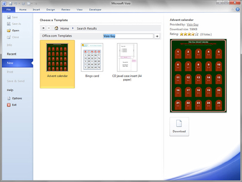
If you can’t find what you want by browsing, there’s a handy search bar just right of the Office.com Templates heading. Figure 2.6 shows the template search in action.
Figure 2.6. The Office.com offerings resulting from a search on “Visio Guy.”
![]() LET ME TRY IT
LET ME TRY IT
Starting a New Drawing from an Office.com Template
- Click the File tab to go to the Backstage area.
- Click New in the list on the left.
- Click Home at the top of the window, under Choose a Template.
- Click Office.com templates at the bottom, under Other Ways to Get Started.
- By either browsing or searching, see whether you can find some of these templates. Go ahead and open them: explore and experiment!
• Rack Design Guideline
• Troubleshooting flowchart
• Process improvement
• Map of Africa
• Family tree
• One week planner
- Remember that when you open a template, you get an unsaved copy of the original. So experiment, play, and mess around to your heart’s content, and have fun. You won’t screw up the original!
Saving Diagrams
You don’t need me to tell you that after investing hours of hard work in a diagram, you should save it. In fact, saving is a real good idea after just minutes of hard work!
Saving Documents Using Save As
The simplest way to save your document is to click the little disk icon in the top-left corner of the Visio application window in the Quick Access Toolbar. Pressing Ctrl+S is even faster if you like keyboard shortcuts. You can also go the more traditional route: choosing File and then Save As.
If a drawing hasn’t been saved, you see a typical Save As dialog. The default save location is your My Documents folder, but you can browse for a target location from there.
If your drawing has already been saved and named, you don’t see anything happen—other than maybe the hourglass cursor doing its thing.
Saving Documents Using Save & Send
When you click the File tab, you see the familiar Save and Save As items atop the list on the left. Further down, you also find Save & Send. The Save & Send pane offers many options for saving, exporting, and sharing your diagrams in a nicely organized, easy on the eyes layout. Save & Send enables you to do the following:
• Save to SharePoint.
• Save in Visio XML format.
• Save in Visio 2000–2002 format.
• Save as a PDF- or XPS-formatted document.
• Export to various graphics formats, such as PNG, GIF, SVG, or EMF.
• Save as a web page.
• Send the file as an email attachment in Visio, PDF, or XPS formats.
You return to Save & Send in Chapter 10, “Sharing, Publishing, and Exporting,” but take a moment now to peruse the options.
Configuring Auto Save
If you don’t habitually hit Ctrl + S like me, you may want to have Visio automatically and periodically do the saving for you. You configure Visio’s automatic saving options in the Backstage area, in the File, Options, Save panel. There you can configure automatic saving options by specifying the default file format and the AutoRecover time increment.
Finding and Managing Shapes
After you are an expert at starting new drawings, you will want to become proficient at finding and dropping shapes! The Shapes window is the key to finding and managing stencils and the master shapes they contain.
Navigating the Shapes Window
When you open a template, you immediately notice the big, vertical Shapes pane docked on the left. The Shapes window, shown in Figure 2.7, is your main stop when looking for master shapes to drag out into your diagram.
Figure 2.7. The Shapes window for the Office Layout template and its key elements.

Much improved in Visio 2010, the Shapes window is the place for managing stencils and masters and searching for shapes.
From top to bottom, the Shapes window has six major parts:
• Shapes header—This header allows you to tear off the entire Shapes window and float it or dock it to other sides of the window, like any other task pane.
The sideways-facing arrow also lets you collapse the Shapes window to free up more space for drawing, then re-expand it to see all the details.
You can right-click the Shapes header to change how master icons are displayed in the Shapes panel, choosing from compact, icons-only, or verbose icon/name/description views. You can also hide the Shapes window entirely via this menu.
• Search for Shapes field—You can enter a keyword and search for shapes by name or description. The results are displayed in a virtual stencil that appears below in the shapes panel.
• More Shapes—It looks like a stencil tab, but it serves only to hold the More Shapes menu, which is expanded in Figure 2.7. More Shapes lets you access all the stencils that come with Visio, along with your favorite shapes, and other stencils on your system. You can also create new stencils from here.
• Quick Shapes—Clicking Quick Shapes reveals a virtual stencil that shows the Quick Shapes for each of the open stencils. We talk more about Quick Shapes in the next section.
• Stencil tabs—Every stencil that is open has a stencil tab in the Shapes window. Click a tab to reveal the master shapes for that stencil in the shapes area below.
There are actually six stencils open with the Office Layout template shown in Figure 2.7, but you can see only a few of them. Note the short scrollbar to the right of the stencil tabs, which you can use to see the stencil tabs that aren’t visible. You can also pull down the splitter between the stencil tabs and the shapes panel to show more stencil tabs (and fewer master shapes).
When you click a stencil tab, it is highlighted in orange, and the stencil’s masters are displayed in the panel below.
You can pull individual stencil tabs out of the Shapes window area and dock them to other sides of the Visio window or just let them float. Figure 2.8 illustrates this. You can drag stencil tabs around to reorder them in the Shapes window, and you can close stencils by right-clicking their tabs and choosing “Close.”
Figure 2.8. Stencils torn away from the Shapes window, docked and floating in various places. Right-clicking the Shapes header allows you to change the way master icons are displayed. Here we see the “Icon Only” view, which is compact and efficient.

• Shapes panel—This panel shows icons for the master shapes in the selected stencil tab. If Quick Shapes is selected, the Shapes panel actually shows master shapes from several stencils.
Quick Shapes—Accessing and Managing Frequently Used Shapes
Quick Shapes show up in the Visio UI as two different entities. First, every stencil has a selection of Quick Shapes at the top. These are the favorites or most frequently used shapes for that stencil. Second, Quick Shapes is a stencil tab that you’ve just seen in the Shapes window.
In Figure 2.9, you can see the Quick Shapes area for the Office Accessories stencil. Look closely for the faint line just after the top four shapes. You can choose which shapes should be Quick Shapes by simply dragging them above the line, and you can demote shapes to be nonquick by dragging them below the line.
Figure 2.9. Quick Shapes for the Office Accessories stencil.

Visio remembers your Quick Shape preferences, but if you want to return things to their pristine state, just right-click a stencil’s tab and choose Reset Stencil. This resets the Quick Shapes and moves each master back to its original position. So don’t be nervous about playing around and trying different arrangements.
Quick Shapes is also a stencil tab in the top portion of the Shapes window. Click it, and you see the Quick Shapes from each of the open stencils. So this Quick Shapes tab isn’t really a stencil that comes from a file on disk, but more of a virtual view of shapes in other stencils that are open.
Oddly, Quick Shapes shows only masters from stencils that are docked in the Shapes window. Quick Shapes from stencils floating elsewhere are not included in Quick Shapes view.
Quick Shapes are also used by the mini-toolbar, which lets you quickly drop and connect shapes. You encountered the mini-toolbar briefly in Chapter 1, “Introducing Visio 2010,” when you created your first flowchart. You revisit it in Chapter 4, “Connecting Shapes.”
Opening Other Stencils
Regardless of the template you start with, you can always open additional stencils. You can open Visio-supplied stencils or stencils that you have saved elsewhere on your hard drive.
Of course you can open stencils using the traditional File, Open dialog, but you’ll find that using More Shapes is much more convenient. It gives you quick access for opening any of Visio 2010’s numerous stencils. You can see how Visio categorizes various groups of stencils by looking at the expanded More Shapes menu in Figure 2.7.
The hierarchy is similar to what you see in the template gallery. Stencils are organized by the following categories: Business, Engineering, Flowchart, General, Maps and Floor Plans, Network, Schedule, Software and Database, and Visio Extras. Some categories have subcategories, but keep digging, and you’ll eventually see little green stencil icons that you click to open libraries of shapes.
Figure 2.7 also shows an expanded My Shapes submenu (That’s “My Shapes” under the “More Shapes” menu, it’s easy to confuse the two!) As you learn to mark your favorite shapes and build up your own custom stencils, you will likely store them in the My Shapes folder. My Shapes is a convenient location for your shapes because it is built into the Visio interface, and eliminates the need to browse the file system.
If you have stencils saved in locations that aren’t part of the My Shapes system, then you will need to browse to them. You can use More Shapes, Open Stencil, or use the File, Open. When the Open dialog appears, note the file type filter in the lower-right corner. Setting it to Stencil (*.vss, *.vsx) makes it easier to find stencils in folders on your PC.
If you open a stencil when no document is open or when all document windows are minimized within Visio, you get a separate stencil window, as shown in Figure 2.10. While you can’t dock separate stencil windows into the Shapes area, they are useful for dragging shapes into several different documents, since they don’t disappear when you switch drawing windows.
Figure 2.10. The Company Logos stencil was opened before the Office Plan drawing. When no drawing is present, stencils open in separate, nondocked windows.

Searching for Shapes
If you’re not in the mood for painstakingly browsing each of Visio’s stencils to find just the shape you need, try searching instead! The Search for Shapes text box atop the Shapes window will help you do this.
Using Shape Search
Say you need a lamp for your office plan. Just type light into the search box and then press Enter (or click the Start Search magnifying glass). Figure 2.11 shows how the results look:
Figure 2.11. Shape Search for the term light creates a temporary virtual stencil with the shapes it found.

The results of your shape search appear as a stencil with their own stencil tab. Like Quick Shapes, this is a virtual stencil that doesn’t really exist as a file but is created on the fly to hold your results.
You can drag any shape from it and then close the stencil. Alternatively, you can save it to your favorites for later use (as a real, live stencil file). Just right-click the tab and choose close or save.
After performing several searches, you might notice that the Shape Search field becoms a drop-down list filled with past search queries. If you frequently search for the same shapes, check the drop-down list and save yourself some typing.
Why Shape Search Results Have Funny Numbers
Figure 2.11 shows many results for the search on “light.” What happened is that Shape Search dug through many stencils, looking for masters that have the word light in their names, keywords, or descriptions.
Within a single Visio stencil, master names must be unique. Having two masters named “Light” is not allowed, so Visio appends a number to make each name different. Even though the search results stencil is temporary, it still has to follow these rules.
If you’ve installed both metric-unit and US-unit content on your machine, you often get double results because Visio finds both the metric and US-units version of the shape. Visio might also find shapes from other sources, such as stencils you’ve downloaded or created yourself. On my machine, I’ve also installed Visio 2007, and Shape Search finds masters from the stencils installed with that product, too.
Saving the Results of Shape Searches Using My Shapes
You can save the results of your searches in a number of ways. You can drag single masters to your favorites stencil, save the entire results as a new stencil, and more.
![]() LET ME TRY IT
LET ME TRY IT
Saving the Shape Search Results
- Start a new drawing from the Maps & Floor Plans, Office Layout template.
- In the search field, type light and press Enter. You should see results similar to those in Figure 2.11. (Note: If you don’t see the Search for Shapes field, click More Shapes and check Search for Shapes.)
- Right-click on the Idea shape (or any shape of your choosing) and choose Add to My Shapes, Favorites. The Idea master is added to your Favorites stencil.
- To see your Favorites stencil, click on More Shapes, My Shapes, Favorites. The Favorites stencil should appear with your newly added master.
- Right-click on the Favorites stencil’s tab and choose Close.
- To save the entire search-results stencil, right-click on the tab that says “light” and then choose Save As.
- In the Save As dialog, set the stencil name to My Lights.vss and then click Save. The caption of the search-results stencil should now change to “My Lights.” It is now a real, saved stencil and no longer a temporary search-results stencil.
- Click More Shapes again and choose My Shapes, Organize My Favorites. An Explorer window opens, showing at least two files: Favorites.vss and My Lights.vss.
- You can easily access your new stencil in the future. Because it is stored in the My Shapes folder, it is directly accessible from Visio’s user interface. To retrieve it, just click More Shapes, My Shapes. You should see My Lights in the list.
- Back in the search field, type in a new expression (in this case, lamp) and then press Enter. You should see several results below in the “lamp” search-results stencil.
- Right-click the Desk lamp master and then choose Add to My Shapes, My Lights.
- If the My Lights stencil is still open, you should immediately see a small, dark-blue disk icon on the right side of the My Lights stencil tab. The reason is that the stencil has been changed: you just added the Desk lamp shape to it. If My Lights was not open, you will see the newly-added lamp shape the next time you open the stencil.
- Click on the My Lights tab to activate the stencil. Scroll to the bottom of the stencil. You should see that the Desk lamp master has been added to the stencil.
- To save the updated My Lights stencil, right-click the tab and choose Save. The disk icon disappears, but a small red star opens in its place. This indicates that My Lights is open for editingso you can add, delete and rename masters.
Configuring Shape Search
You can fine-tune the way Visio searches in one of two ways:
- Right-click the Shapes window title bar and then choose Search Options.
- Go to File, Options, and choose the Advanced tab.
Both methods take you to the same dialog, but beware! The Advanced tab has five sections, each with a bunch of options, so you need to do some scrolling. To configure Shape Search, scroll all the way to the bottom. The second-to-last section has the options you’re looking for, as shown in Figure 2.12.
Figure 2.12. Shape Search options in the Backstage area. Be sure to scroll to the bottom of the panel; otherwise, you won’t see the options in the Shape Search section.

The options for Shape Search are few, but one of the coolest options is the Sort Results setting. If you select By Group, your results are categorized by containing stencil, as shown in Figure 2.13.
Figure 2.13. Search-results stencil for “light,” sorted by group. Note stencils ending with “_M” are metric, those with “_U” are US units, also known as imperial units.

This capability is reminiscent of how the Quick Shapes window displays shapes from each open stencil. It is easy on the eyes when there are a lot of search results, and clearly shows double results from the Metric and US units stencils.
Knowing the stencil name is also great if you want to explore the rest of the shapes in the source stencil. Sadly, there’s no shortcut that takes you straight to the original stencil. You have to go back to the More Shapes menu and dig around until you find the source stencil’s name in the menus.
Saving Favorite Shapes
As you spend more time using Visio’s stencils and templates, you will come across shapes that you want to bookmark as favorites.
Just as you can save shapes from a Shape Search, you can add any shape you see in any stencil to your favorites. To do so, right-click a shape in the stencil, click Add to My Shapes, and then select a stencil from the list. You can also choose to create a new stencil if Favorites is getting overcrowded, or you need sets of favorites for different diagram types.
Figure 2.14 shows the Coffee icon from the Symbols stencil being added to my Favorites stencil.
Figure 2.14. Saving an existing master to Favorites by right-clicking and then choosing Add to My Shapes.

Managing and Organizing Your Favorite Shapes
In the previous Let Me Try It, you briefly saw the My Favorites folder, which you can quickly get to via More Shapes, My Shapes, Organize My Favorites. This folder has special status in that its contents are shown in the My Shapes and Add to My Shapes cascading menus.
Figure 2.15 shows the expanded More Shapes, My Shapes menu, along with the corresponding Explorer window.
Figure 2.15. The My Shapes menu item reflects the stencil-containing structure of the My Documents, My Shapes folder on your system.

You can see that I’ve added a few stencils of my own to the My Shapes folder: My Demo Stencil 1, My Demo Stencil 2, and VBA Code Library. They also appear in the My Shapes menu.
Note that My Shapes can even contain subfolders. In Figure 2.15, you can see that I’ve quickly added a new folder, named (cough) New Folder. This contains the stencil named My Demo Stencil 3. This capability is great for further organizing your Favorites because subfolders just become another level of cascading menu inside the Visio interface. If you have tons of favorites and custom stencils, you can keep them sorted using subfolders but still have them handy via the My Shapes menu.
If you download or purchase Visio shapes from a third party, it’s a good idea to put the files in the My Shapes folder. That way, they are easily accessible from within Visio. Of course, you could put them in any folder on your system, but then you need to browse to them.
Editing Existing Stencils
Using the various My Shapes mechanisms to add shapes to stencils is quick and convenient. You can also drag masters from stencil to stencil or even create new ones by dragging shapes you create from the page onto a stencil. You can also delete shapes from stencils by selecting them and then pressing the Delete key.
However, there are a few gotchas that might trip you up when you try to edit a stencil.
The first is that stencils normally open read-only. If you want to edit a stencil, right-click on its caption bar and then choose Edit Stencil. After you do this, a little red star shows up, indicating that the stencil is now open for editing. If you make changes to the stencil, a little disk icon appears in place of the red star. This icon indicates that the stencil needs to be saved, which you can do by clicking the disk icon.
The second problem is that stencils that come from Microsoft with your Visio installation cannot be edited, no matter what you click. Figure 2.16 shows a fruitless attempt to make the Symbols stencil editable.
Figure 2.16. Right-clicking the Symbols stencil’s caption shows that Edit Stencil is grayed-out and not available.

One work-around is to save a copy of the stencil and then make changes. For instance, you could right-click the Symbols caption, choose Save As, and then save it to your favorites as, say, “My Symbols.” Now you can freely add and delete shapes from this stencil using the methods just discussed.
Creating a Custom Master Shape and a Custom Stencil
All this talk of editing and managing shapes and stencils might have you dreaming up your own custom libraries of shapes. So let’s go over the basic steps for creating a new stencil with a new master.
Creating a New Stencil with New Masters
- Create a new Blank drawing.
- Using the Rectangle and Ellipse tools, draw a few basic forms. Position them near each other or even overlapping.
- Format the shapes with crazy colors and line styles. Have fun, go crazy!
- Select the Pointer tool, and select all your shapes by dragging a selection rectangle around them.
- Group them together by pressing Ctrl+G or right-clicking Group, Group. You now have a single shape composed of several subshapes. You can save this shape in a stencil to make it easy to reuse.
- Create a new, blank stencil. Go to More Shapes, New Stencil. You should see a new stencil window that has a name like Stencil1 or Stencil2.
- Drag your grouped shape from the drawing page onto the stencil. You should see a new master with a name like Master.1 or Master.2.
- Edit the name of the master by right-clicking and choosing Rename Master. Enter a name for your new shape, such as “My First Shape.”
- Notice that the stencil now shows the disk icon in the upper-right corner. This indicates that the stencil has been changed and should be saved. Click the disk to save the stencil. The Save dialog appears, showing the My Shapes folder by default. Enter a name for the stencil and click Save. The new name of the stencil now shows in the stencil tab caption.
- You can edit the properties for your stencil by right-clicking the stencil tab and choosing Properties. There you can edit fields such as Title, Subject, Author, Manager, Company, Language, Categories, Tags, and Comments. Notice that if you customize the Title, it appears in the stencil’s caption instead of the filename.
- You can also edit the master shape itself. Double-click the master icon or right-click and choose Edit Master, Edit Master Shape. You then see a new window that shows just the innards of the master. Try changing a few colors or adding some text. When you’re done, click the x to close the master window. If you made any changes, you see the alert “Update My First Shape?” Click Yes to accept your changes. Notice that the master icon visually updates to reflect your alterations.
- Test your new master shape by dragging and dropping it onto the drawing page.
Understanding the Document Stencil
When you drag masters into a drawing, not only do you get a shape on the page, but you also get a copy of the master inside the document itself. Every document has an “internal” or “local” stencil called the document stencil. Working with the document stencil is considered an advanced Visio topic, but I think that understanding it helps avoid confusion down the road, and deepens your understanding of Visio.
Show Me: Media 2.2—Understanding External Stencils, Local Masters, and the Document Stencil
![]()
Access this video file through your registered Web Edition at my.safaribooksonline.com/9780132182683/media.
![]() LET ME TRY IT
LET ME TRY IT
Working with the Document Stencil
- Start a new diagram using the Basic Flowchart template.
- On the Design tab, in the Themes group, click the left-most theme called No Theme to remove any theming from the drawing.
- Click My Shapes and then choose Show Document Stencil from the bottom of the menu. A blank stencil window appears with “Document Stencil” as its title. This internal stencil holds copies of masters dragged into the drawing, and belongs to the document itself. It isn’t a separate stencil file.
- Move the Document Stencil to the right side of the window by dragging its stencil tab. See whether you can get it to dock to the right side of the drawing window.
- In the Shapes window, click Basic Flowchart Shapes.
- Drag the Decision shape onto the page. You see a diamond on the page as expected, and a Decision master also appears in the Document stencil. This is the local copy of the master!
- Drag several more Decision shapes onto the page. Select one and resize it to be narrower. Select another and type the text “A Decision.”
- Double-click the Decision master in the Document stencil. A new window appears showing just the diamond shape. This is the master editing window. (You don’t have to enable the Document Stencil for editing, because it belongs to the document that you are already editing!)
- Select the diamond and type “Yes or No?” for its text.
- Stretch the diamond and make it wider.
- Give the shape a gaudy fill color such as red or orange. You can do this by right-clicking and picking a color from the fill bucket drop-down.
- Close the master editing window by clicking the “X” in the top-right corner (make sure you don’t close the whole Visio application!).
- Accept the changes by clicking “Yes” when the warning: “Update ‘Decision’ and all of its instances?” appears.
Notice that the Decision shapes on the page have updated to reflect the changes you made to the master. However the shapes that you edited on the page before editing the master, don’t get every single change that you made. The “A Decision” shape’s text is unchanged, and the narrower shape didn’t become wider. Changes made to shapes on the page override changes made to the master.
Clearly the Document stencil offers a lot of power and potential for quickly changing your documents. But let me point out a few caveats and common misconceptions.
• The stencils that open with a template are actually separate files. When a master from an “external stencil” is dropped into a document, it is copied to the document stencil, as you’ve just experienced. Only changes to the master in the document stencil affect shapes in the drawing. Changes to the original master in the original stencil do not affect dropped shapes.
• If you drag masters from various stencils onto a page and then delete them, there are still copies of those masters in the document stencil. This leads to mysterious file bloat: you could have a completely blank document that has a huge file size because the document stencil is full of masters that were dropped and then deleted. File, Info, Reduce File Size (discussed in Chapter 10, “Sharing, Publishing, and Exporting”) can help you to detect and remove unused local masters.
• Not all changes that you make to Document stencil masters will propagate to shapes on the page. If shapes have been modified on pages, those changes take precedence over changes made inside the master, as you saw in the excercise.
• Editing Document Stencil masters seems like a great way to replace shapes. While this works to some extent, you could get some unexpected results. Small changes to masters usually propagate just fine, but complete replacement of the innards of a master can lead to surprises.
Managing and Styling Pages
Now that you know how to create new drawings and find plenty of shapes to add to them, let’s look at how to create and manage pages themselves. Visio documents can contain multiple pages of different sizes, scales, and orientations. This capability is great for breaking up complex diagrams into simpler pieces or for keeping different types of diagrams together in a single project.
Inserting Pages
You might want to add pages to a Visio document for lots of reasons. Some projects require several different types of diagrams, and keeping them all in a single drawing file but on separate pages is convenient. For example, the drawings for a system installation project typically require a title page, several scaled plan and elevation views that show the site and actual views of real equipment, plus unscaled schematic and wiring diagrams that show how to hook everything up.
Other drawings are so complicated that it helps to break them down into overview and detailed views. Large organizational charts and complicated process flows benefit from using multiple pages to “drill down” in the hierarchy. For these diagrams, separate pages in a Visio document contain simplified high-level views and detailed low-level views.
Adding Pages Quickly
The fastest way to insert a new Visio page is to click the Insert Page tab on the right end of the page tab bar, as shown in Figure 2.17. If you use Microsoft Excel, this will be second nature for you.
Figure 2.17. The Insert Page tab allows you to add new pages, similar to how you add new sheets in Microsoft Excel.
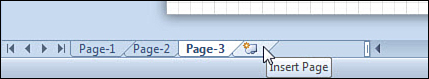
When you click this tab, a new page is added to the end of your document. The new page has the same size, scale, and orientation as the active page. You therefore get a fresh copy of whichever page is showing but without any shapes.
On the Ribbon, the Blank Page button on the Insert tab also lets you add new pages. Figure 2.18 shows the Blank Page button with expanded choices.
Figure 2.18. Adding pages via the Insert tab’s Blank Page button.

Simply clicking the Blank Page button gives the same effect as clicking the Insert Page tab at the bottom of the window. Use the drop-down functionality for finer control.
Adding Pages with the Page Setup Dialog
As you become a more sophisticated Visio user, you might want more control over the pages you insert. The Page Setup dialog offers many options for specifying the name, size, scale, measuring units, layout settings, and more.
To access the Page Setup dialog, right-click a page tab for an existing page and then choose Insert. The Page Setup dialog opens, as shown in Figure 2.19.
Figure 2.19. The Page Setup dialog gives you full control over new pages, as well as existing pages. Note that this dialog has six different tabs.

Notice that the Page Setup dialog box has six different tabs. Clearly, adding a page using this method offers a lot of control over many aspects of the new page. Page Setup can be used to fine-tune existing pages as well. Just right-click a page tab for an existing page and choose Page Setup (see Figure 2.19).
We revisit the Page Setup dialog many more times throughout the book. For now, take a few moments to familiarize yourself with the different tabs and options available in it.
Show Me: Media 2.3—Adding and Manipulating New Pages
![]()
Access this video file through your registered Web Edition at my.safaribooksonline.com/9780132182683/media.
Adding and Manipulating New Pages
- Create a new blank drawing. It should have one page, with one page tab at the bottom displaying Page-1.
- Quickly add several pages by clicking the Insert page tab on the right end of the page tab bar several times. Note that pages are added to the end of the document and are automatically named in order: Page-2, Page-3, Page-4, and so on.
- Draw different shapes on each page of the document using the Rectangle or Ellipse tool. Click the page tabs to go back and forth in the document and view different pages.
- Note the rewind, forward, backward, and fast-forward buttons to the left of the page tabs. They help you to scroll tabs when you have more pages than can be shown in the page tab area.
- You can quickly jump directly to any page in the document by right-clicking any of these controls and then choosing a page from the list.
- Rename any of your pages by double-clicking a page tab. This should activate text editing so you can type in a new name for the page.
- Add a new page using the Page Setup dialog. Right-click a page tab for an existing page and choose Insert.
- In the Page Setup dialog, type a custom name for the page. Experiment with other settings on the tab and see what features of the new page you can control. After you click OK, you should see your new page at the end of the page tab bar.
- Change the name of another page by right-clicking its page tab and then choosing Page Setup. The name of the page should be highlighted in the Name field for you to change quickly.
- Reorder the pages by simply dragging page tabs to and fro.
Working with Background Pages
Background pages are special pages whose content shows on foreground pages but can’t be edited from the foreground. Because background pages can be shared by multiple foreground pages, they can save you a lot of work and make your documents more efficient. Common elements can be shared by many pages, and updated in only one place!
A common use for background pages is for holding titles, borders, and background art for an entire document.
![]() LET ME TRY IT
LET ME TRY IT
Adding Background Pages Using Borders and Titles
- Create a new drawing, either blank from a template or from a sample drawing.
- Drop or draw a few shapes on the default page.
- Click the Design tab.
- In the Backgrounds group, select a background from the Backgrounds gallery. Notice that you now have background graphics, and a new page tab has been inserted: VBackground-1 (see Figure 2.20). The name of the new page appears in italic, and is at the right end of the page tabs, two clues that a page is a background.
Figure 2.20. Inserting the World background creates a new background page called VBackground-1.

- Add a title by selecting an item from the Borders & Titles gallery. The item appears, but no new page tab is added.
- Try to select the border or title shapes. Notice that you can’t do this. Both the background graphics and title have been added to the VBackground-1 page. They show through to Page-1 but can’t be edited from there.
- Now go to the new background page by clicking its page tab.
- Try to select the border or title shapes. Notice that this time it works.
- Add some more shapes to the background page. Drop shapes from stencils or just draw rectangles and ellipses.
- Return to the original page by clicking the Page-1 tab. Notice that you can see the shapes that you added to the background page, but you can’t select them from the foreground page.
- With Page-1 active, click the Insert Page tab. You should see a new (foreground) page tab named Page-2.
- Click Page-2’s tab (if it isn’t already active). Notice that the background graphics show for Page-2 as well. Remember that a background page can be shared by multiple foreground pages, and when you insert a page, the current page’s settings are copied, including background page assignments.
If you look at your page tabs, you can see that your document now has three pages. When you print your document, however, only two pages will come out. The reason is that background pages don’t print as separate pages, but their content prints on foreground pages that reference them.
It is worth noting that background pages can themselves have background pages. A foreground page could have a background page that in turn has another background page and so on. You can create complicated (and confusing) chains and hierarchies of background pages, several layers deep. For certain applications, this capability is quite useful, but you’ll want to guard against complexity that will make maintenance and modification difficult.
Imagine you are designing different web page templates for a website. Every page in the site has the same header and footer, but some page types have different sidebars and navigation menus. In Visio, foreground pages could represent actual web pages in the site. These then reference background pages for their sidebar treatments, and those backgrounds reference the header and footer background. If you needed to change, say, the company logo in the header, you only need to edit the backmost background page, and all of the foreground pages would show that change.
In the previous example, background pages were created for you automatically. To build sophisticated structures like a layered website, you need to know how to create and assign background pages manually.
Show Me: Media 2.4—Adding Background Pages Manually
![]()
Access this video file through your registered Web Edition at my.safaribooksonline.com/9780132182683/media.
![]() LET ME TRY IT
LET ME TRY IT
Adding Background Pages Manually
The process of manually creating background pages is a bit more involved but allows finer control. Be sure to notice the key step of assigning the background page to a foreground page.
- Create a new blank drawing.
- Click the Insert tab on the Ribbon.
- In the Pages group, click the Blank Page drop-down and select Background Page. Alternatively, right-click a page tab and choose Insert. The Page Setup dialog appears.
- Set the Type to background by clicking the Background radio button.
- Enter a name for the page. Background-1 is the default, but shorter names reduce clutter in the page tab bar. I usually use something like bg1. Click OK and a new page is added. The page should be active in the drawing window, and its page tab should be at the far right.
- On your new background page, draw a large rectangle and type Hi, my name is Background.
- Return to Page-1. Notice that you do not see the shape you just created. The reason is that the background has not yet been assigned.
- Right-click on the page tab for Page-1 and choose Page Setup. You should see the Page Setup dialog, with the Page Properties tab active.
- In the Background drop-down, choose the name of the background page that you just created and then click OK. You should now see the “Hi my name is Background” shape showing through.
- With Page-1 still active, click the Insert Page tab to add a new page. A new page named Page-2 should be added, and you should still see the background graphics. The new page is copied from Page-1 and retains its settings, including the assigned background.
- Right-click Page-2 and choose Page Setup.
- In the Background drop-down, choose None; then click OK. The background shapes should now be gone from Page-2. You have just unassigned the background page from Page-2.
Inserting Backgrounds, Titles, and Borders
You’ve seen the Design tab’s Backgrounds group which contains two galleries for quickly adding backgrounds, borders, and titles to your document.
When you pick one of these elements, Visio automatically creates a background page to hold the background graphics, borders, or titles you choose. Backgrounds are easily identified by their obvious names, italic text, and positioning at the end of the page tabs.
Putting titles and other graphics on background pages makes it easier for new foreground pages to share the background graphics. The structure of your Visio document becomes similar to Backgrounds and Background styles in PowerPoint. It also makes it easier to work on foreground pages, as you don’t have to worry about accidentally selecting and moving background shapes.
Backgrounds, titles, and borders that you add from the Ribbon are actual shapes dropped on the background page. You can go to the background page and manually alter them. However, many of them are designed to automatically stretch to the size of the page, or be positioned on one edge, so you might not be able to freely resize or reposition them.
If you pick new border, background or title styles from the Design tab, Visio deletes existing shapes and replaces them with new ones. You don’t have to worry about creating a stack of shapes on the background page, one on top of the other.
Many of the titles have text that indicates the page number. If you look at the page number while a background page is active, you’ll see something like Page 0, which can be disconcerting. Don’t worry, though; the page number is an inserted field that is smart enough to change for each foreground page (go look at the foreground pages and you’ll see reasonable page numbers). We talk more about inserting smart fields into text blocks in Chapter 3, “Organizing and Annotating Diagrams.”
You also see the word Title in many of the title shapes. This field is not smart in any way, even though it would make sense to link it to the Title field from the document’s properties (again, discussed in Chapter 3, “Organizing and Annotating Diagrams”). At any rate, you have to go to the background page to edit it. Just click on the background page tab, select the title shape, and then type your own title text.
Renaming Pages
Your pages don’t have to be named Page-1, Page-2, and so on. You can change them to anything you like. All you have to do is double-click a page tab and type in a new name. This is the same as right-clicking a page tab and choosing Rename, but double-clicking is much easier.
You can also go to the Page Setup dialog to rename a page. Just right-click a page tab, click Page Setup, and then enter a new name in the Name field on the Page Properties tab.
Reordering Pages
Reordering pages is as simple as dragging the page tabs around, just as you would in Excel.
If your document has lots of pages, dragging tabs from one end of the document to the other can be difficult. But there’s help! Right-click any page tab and choose the last menu item: Reorder Pages. In the dialog that pops up, you can reorder your pages by using the Move Up and Move Down buttons. Your pages clearly move up and down in the list box, as shown in Figure 2.21.
Figure 2.21. The Reorder Pages dialog is great help when you have lots of pages to move around.

A great feature of the Reorder Pages dialog is the Update Page Names check box. If you leave this box checked, any pages that have the default page names (Page-1, Page-2, Page-3, and so on) are updated to reflect their new positions in the document.
In Figure 2.21 the Table of Contents page is being moved from the end to the beginning of the document. After the move, Page-1 will become Page-2, Page-2 will become Page-3, and on. But you might not want this change because the table of contents is more like a Page-0. In such a case, you should uncheck Update Page Names before moving any pages.
One last note: background pages always appear at the end of the page tab list, and can’t be reordered.
Controlling Page Size and Orientation
You can set your Visio pages to any size and orientation you want. Perhaps you want to work with sheets that adhere to standard paper sizes, or maybe you want your page to expand ad infinitum as your drawing grows. For wide drawings, you’ll want a landscape orientation; for tall diagrams, portrait.
Whatever your needs, your first stop is the Design tab. On the left you find the Page Setup group, which contains three handy buttons: Orientation, Size, and AutoSize.
Setting Page Orientation
You can set your page to landscape or portrait orientation in a snap by clicking the Orientation drop-down button. Switching between wide and tall drawing pages couldn’t be easier!
Setting the Page Size
The next button in the Page Setup group, Page Size, offers you a long drop-down list full of standard office paper sizes.
Engineers and architects might want to click More Page Sizes at the bottom of the list. This pops up the Page Setup dialog, with the Page Size tab highlighted. There you can pick from Metric (ISO), ANSI Engineering, or ANSI Architectural standard page sizes. You also can enter custom values for your page size.
It is important to understand that the size of the Visio drawing surface does not have to match the size of the paper in your printer! When you want to print, pages can be scaled up or down to fit the printer’s paper or tiled across several sheets. We talk more about this topic in Chapter 9, “Printing.” For now, you can create any drawing page size you want and worry about how to print it out later.
Specifying Auto Sizing Pages
Some diagram types have a tendency to meander. Network diagrams, flowcharts, and other process diagrams can just grow and grow! For these types of diagrams, the AutoSize button is great, and saves you a lot of time horsing around with page size settings.
With AutoSize checked, your drawing just grows when you drop a shape in the blue “off-page” area. Visio automatically extends your drawing by one sheet of paper in the direction that you are working, and you never have to worry about running out of space again. If you remove all shapes from a page tile, then AutoSize will remove the tile and your page size contracts.
For some folks this feature is a scourge. The pasteboard (blue off-page area) is great for holding temporary graphics, clipboard scraps, and other temporary junk that you want to have around but don’t want in the drawing itself and don’t want to print. If you’re the type that likes storing bits and pieces “off stage,” then you will want to turn AutoSize off, which you can easily do by clicking the AutoSize button on the Design tab. Problem solved.
![]() LET ME TRY IT
LET ME TRY IT
Using AutoSize Versus Manually Resizing Pages
If you create sprawling network or flowchart diagrams, you’ll love AutoSize. If you like using the pasteboard, you won’t like AutoSize. If you like both features, there is a happy middle ground that lets you quickly and easily resize the page at your leisure without resorting to the Page Setup dialog.
- Start a new drawing using the Basic Flowchart template.
- Go to the Design tab and turn on AutoSize (it is on by default for this template, but double-check).
- Drop some flowchart shapes on the page.
- Try dropping more shapes in the blue pasteboard area. See how Visio automatically extends the drawing surface by one page?
- In the View tab, make sure that Show, Page Breaks is checked. As AutoSize expands your page, you see dashed lines that indicate how your drawing will be tiled when you print. This capability helps you avoid dropping shapes in awkward positions that land directly on the page break, where they might get mangled in printing.
- Now go to the Design tab and turn off AutoSize.
- Drop more shapes in the blue area. The page no longer expands automatically, and you can store shapes off-page in the pasteboard region. Note that shapes on the pasteboard won’t print.
- If you decide that you want to expand the drawing, there is a shortcut that lets you quickly and visually expand te page without having to reactivate AutoSize. In the drawing window, move your cursor to an edge of the drawing page—where the white meets blue. Hold down the Ctrl key. Your cursor should change to a double-headed resizing arrow.
- While still pressing the Ctrl key, hold down the left mouse button and drag the border of the page to a new location. See how you can quickly resize the page to any dimensions you like?
I think that the manual page resizing is a nice middle-ground between AutoSize and Not AutoSize. One minor drawback is that you end up with completely arbitrary page sizes, instead of the integral numbers of sheets that AutoSize provides. This isn’t a huge problem because you have a lot of control at print time regarding scaling and page tiling anyway. If you are adamant about having exact numbers of page tiles, however, you should use AutoSize.
Setting Page Scales
Engineers and architects create drawings that represent objects in the physical world. They use page scales to relate real-world sizes to on-paper sizes. Scales allow them to easily draw objects that are much bigger (or much smaller) than the physical paper, without doing lots of mathematical conversions in their heads.
For example, imagine your office measures 10 by 12 feet. To fit a drawing of the office onto an 8 ½″ × 11″ letter-sized page, those 10 feet (120 inches) have to fit onto 8 ½ inches of paper! This means that each inch on the paper has to cover at least 14.1 inches in the real world.
Dividing every measurement by 14.1 would be error prone and tedious. Luckily, Visio supports scaled drawings and automatically does the math for you! For the office plan, you could use a standard architectural scale like ½″ = 1′ − 0″. This gives you a ratio of 1:24, meaning that 1 inch on the paper covers 24 inches of real-world space—more than enough to fit the office onto a letter-sized page. At this scale, the page represents 22 × 17 feet of real world space. That’s enough for your office, a title block, and maybe some notes around the edges.
You can set the scale of a drawing by going to the Page Setup dialog and then clicking the Drawing Scale tab, as shown in Figure 2.22.
Figure 2.22. Selecting an architectural scale for an office plan using the Page Setup dialog.
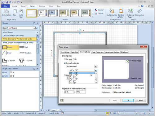
The Drawing Scale tab has three radio buttons for configuring your page’s scale: No Scale, Pre-defined Scale, and Custom Scale.
No Scale is just a 1:1 ratio. You use this scale for schematic diagrams such as flowcharts, network diagrams, and block diagrams. For measured drawings, you can choose Pre-defined Scales that follow Architectural, Civil Engineering, Metric, or Mechanical Engineering standards. Custom Scales enable you to enter any ratio you’d like. You could enter 1 cm = 1′ − 2″ if you want! Custom scales are good for using the paper to its fullest because using standard scales often leaves left-over space.
The Office Layout template that ships with Visio comes preconfigured with the Architectural scale of ½″ = 1′ − 0″ (1:24) for US units and 1:25 for Metric units. The shapes that open with this template also are created to scale. For example, the Sofa shape from the Office Furniture stencil drops on your page at 7 feet × 2 feet 6 inches—a typical sofa size. You can see the size of a selected shape by looking at the status bar in the lower-left corner of the Visio application window or by looking at the Size & Position window (turn it on by choosing View, Show, Task Panes, Size & Position).
When choosing scales, note the two fields under Page Size (In Measurement Units). As you change the scale, these fields update to reflect the width and height that your page represents in the real world. This lets you double-check that the space on your page is big enough to fit the object you are drawing.
Using Themes to Change the Look of Pages and Documents
Themes allow you to change the look of a single page or all pages in your document at the click of a mouse. Using themes is much easier than formatting individual shapes, and themes help you maintain consistency in your diagram.
Some might view themes as eye-candy, but I think that themes offer more than “just a pretty face.” If you are printing drafts of a diagram to a black-and-white printer, a simple, low-color theme saves toner. If, however, you want to use your drawing in a presentation or publish it to the Web, black-and-white will bore your audience. Choosing a vibrant theme can spice up your drawing and keep your viewers interested. Themes are great for matching corporate style guidelines, and Visio’s themes match up with PowerPoint’s, letting you seamlessly use Visio graphics in your presentations.
Using the Theme Gallery Control
You saw how easy it was to apply a theme to your first basic flowchart in Chapter 1, “Introducing Visio 2010.” Let’s revisit them and have a look at the details. The Design tab has a Themes group that contains a gallery of themes. Each theme shows a preview of the theme’s colors, fill effects, fonts, corner-rounding, and arrowhead treatments. You can scroll the theme gallery or drop it down to see more themes.
Remember that themes have Live Preview enabled, so you can “look without buying.” If you hover your mouse cursor over a theme, the drawing changes to show you how it will look with this theme. If you like the look, click the theme to apply it to your diagram. If not, move your mouse cursor away and your diagram reverts to the way it was.
![]() LET ME TRY IT
LET ME TRY IT
Changing Themes for Pages and Diagrams
- Create a new workflow diagram (located in the Flowchart template group).
- Drop some of the snazzy workflow shapes onto the page. Add some text to the shape and make sure that a few of the shapes are connected.
- Add a background and a title using the Backgrounds and the Borders & Titles controls on the Design tab.
- Add a new page or two to the document using the Insert Page tab. The new pages should have the same background as the first page.
- Copy shapes from the first page and paste them onto the new pages. You should have something similar to that shown in Figure 2.23.
Figure 2.23. A workflow diagram with a background page that contains background-graphics, a title, and a company logo.

- On the Design tab, hover over various themes in the theme gallery. Notice how Live Preview gives you a peek at what the theme will look like in your diagram.
- Apply various themes by clicking items in the theme gallery. Notice how the colors and styles on the background page change too.
- Notice that the stencils in the Shapes window also update to reflect the current theme.
- Click the drop-down button for the theme gallery to reveal more themes, as shown in Figure 2.24. Notice that the theme’s name appears when you pause the mouse cursor over an item.
Figure 2.24. The expanded theme gallery. ToolTips reveal the name of each item.

- There are three areas in the drop-down separated by shaded bars: No Theme, This Document, and Built-in. You can click No Theme at any time to bring your drawing back to its original, “unthemed” state.
- Visit the other pages in your document by clicking the page tabs at the bottom. Notice that the other pages have the theme that you chose.
Setting Themes, Theme Colors, and Theme Effects
To the right of the theme gallery are two small drop-down controls labeled Theme Colors and Theme Effects. Themes are actually combinations of color sets and graphical effects. Effects include fonts, fills, lines, arrowheads, and shadows.
This separation is great if, for example, you like the colors of a particular theme, but would rather have different graphical effects. Instead of looking for a different theme altogether, just drop down the Effects list and look for different combinations of line, fill, text and shadow while leaving the colors untouched.
Notice that each item in these drop-downs has a name below the icon. These make it easier to match the style of your Visio diagram to that of a PowerPoint presentation.
Visio Theme Colors match up reasonably well with those in PowerPoint, but the names of effects do not. The reason is probably that PowerPoint’s effects change the layout and look of the slide in addition to graphical styles. So PowerPoint’s notion of an “effect” is quite a bit different from Visio’s.
Applying Themes to Pages versus Documents
Themes can be applied to all the pages in a document or to just one page at a time. If you right-click an item in the theme gallery, you see two choices: Apply to All Pages and Apply to Current Page.
These settings are sticky; whichever setting you choose becomes the default. For example, if you right-click a theme and then choose Apply to All Pages, your entire document gets the theme you clicked. The next time you click a theme, every page will change to the new theme as well! There is one tricky gotcha involved here. Themes can’t be independently applied to pages that share the same background. Take the foreground pages for the document in Figures 2.23 and 2.24. These pages share the same background. If you change the theme for one page, the other page’s theme changes too. It doesn’t matter which Apply setting you use.
Of course, if your document has multiple pages that use different backgrounds or no background at all, you can freely apply different themes to different pages.
Themes that you use in a document show up in a short list that helps you to remember which ones you’ve already used. Notice the This Document area of the themes gallery (refer to Figure 2.24). If you hover over one of these items, the ToolTip tells you which pages the theme is used on, plus the theme’s name. For example, you might see “Aspect colors, Simple Shadow effects: Used by page(s) 3–4.” Very useful information if you have a complex document with many pages.
Preventing Theming
Sometimes, you don’t want shapes to react to themes. A simple example of this is a Stop Sign shape. It should always be red with white text, and doesn’t need rounded corners, transparency, or soft shadows.
You have already seen a shape that ignores themes for good reason. Take another look at Figures 2.23 and 2.24 and notice the Emerald Ecological Enterprises company logo in the upper-right corner. Regardless of the theme applied, its colors and effects remain unchanged. This is good, because we wouldn’t want the corporate folks to come down on us for mangling company branding
You can easily prevent a shape from reacting to themes. Right-click it, click Format, and then uncheck Allow Themes. This works best if you choose this setting while your drawing still has No Theme applied. If your shape has already been inadvertently themed, click Remove Theme in the same submenu.
Another way to make theme-proof shapes is to format them with Standard Colors, instead of Theme Colors, which we discuss next.
Setting Color Palettes and Themes
When you format the color of a shape’s line, fill, or text, Visio presents a color palette with several sections. In Figure 2.25, you can see that the drop-down palette has Theme Colors, Standard Colors, and Recent Colors sections.
Figure 2.25. Theme Colors change when themes change. Standard and Recent Colors remain the same.
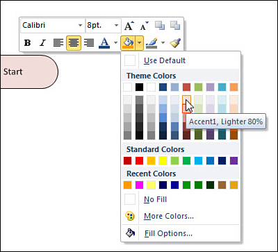
You’ve probably noticed that theme colors change with the theme. Because of this, they have names. In Figure 2.25, you can see the ToolTip under the mouse: “Accent 1, Lighter 80%.” This indicates that you are applying an “80% shade” of the “Accent 1” color to the shape.
If you explore the columns of colors in the color palette, you see that they are named White, Black, Background, Line, Fill, Accent1, Accent2, Accent3, Accent 4, and Accent 5. Because colors can float with themes, it helps to think about the name of the color and what you are applying it to. Instead of thinking, “Oh, let’s make this shape’s outline mauve!” you might instead think, “Hey, let’s apply the theme’s Line color to the outline of this shape!”
If you don’t want your colors to float with the theme, use a color from the Standard Colors or Recent Colors region. This approach makes sense for things like a stop sign, where you’d want white text and a red fill, no matter the theme. You can also click on More Colors to access a full-spectrum color palette and a wider range of standard colors.
Using Visio Windows
Visio is a multiple-document interface (MDI) application, which means you can have several documents open at once, and all the documents are contained within Visio’s main window. Contrast this with, for example, Microsoft Word, in which each document has an entirely separate window.
Visio basically has three levels of windowing:
• The main application window
• Drawing windows
• Task panes
Drawing-level windows also include group-editing windows, master-editing windows, and separate stencil windows, along with the ShapeSheet window which you learn about in Chapter 11, “Developing Custom Visio Solutions.”
Task panes are generally owned by drawing windows. They can be anchored or docked to sides and corners of drawing windows, or they can freely float in space. You’ve seen task pane windows already, but the complete list includes the following:
• Shapes
• Stencils
• Size & Position
• Pan & Zoom
• Document Explorer
• Task panes for specific templates and custom Visio solutions
Figure 2.26 shows a rather busy sampling of Visio windows. You see two different drawing windows. The workflow drawing on the left has a collapsed Shapes window, a stencil anchored to the top-right corner, the Size & Position task pane anchored to the lower-left, and a separate ShapeSheet window for the selected shape at the bottom. The directional map window on the right shows the Pan & Zoom window in the lower-left corner, in addition to an expanded Shapes window.
Figure 2.26. Window soup: Multiple drawing windows are open, along with several task pane windoqs, and a ShapeSheet window.

You can show other task panes by going to the View tab and then clicking the Task Panes drop-down button in the Show group (refer to Figure 2.26).
Managing Windows
Because of Visio’s different window-within-window levels, there are a few points to consider when managing windows.
Minimizing and Maximizing Drawing Windows
Because drawing windows are inside Visio’s application window, they have their own set of minimize and maximize buttons. These buttons can jump around, depending on whether or not your window is maximized.
In Figure 2.27, the drawing window is not maximized, so it has its own frame that you can tug on. Its minimize, maximize, and close controls are in the upper-right corner of the window, as you would expect.
Figure 2.27. A nonmaximized drawing window.
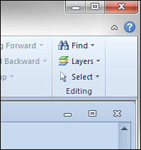
In Figure 2.28, the drawing window is maximized. Notice how its window controls have jumped up to the top of the application window. They’re above the Ribbon just under the Visio application window controls. If you aren’t used to seeing this behavior, it can be a bit of a surprise!
Figure 2.28. A maximized Visio window. See how the min, max, and close controls jump up above the Ribbon?

Switching Between Windows
If your drawing windows are maximized, you don’t see any of the other windows’ frames. If they aren’t maximized, they can still be hidden behind one another, and minimized windows can be easy to overlook.
There are several ways to navigate between windows:
• Pressing Ctrl+Tab cycles through the windows.
• The Switch Windows button in the lower-right corner shows a pop-up list of open windows. This is the last button in the status bar, just to the right of the magnifying glass icon. Click on it, and you can choose from windows that are open in Visio. It is helpful for discovering windows you didn’t think were open!
• In the Window group on the View tab, the Switch Windows button provides a drop-down list of available windows.
The View tab’s Window group also contains controls for arranging and cascading all open windows. These come in handy when you have many windows open, start to lose track of them and need to tidy things up.
You can open new windows using the New Window button. This lets you look at different pages within a drawing or even compare different locations on the same page.
Positioning Task Panes
Task pane windows behave a bit differently, however. They can float in space or be docked or anchored to sides of a drawing window. When panes are docked, you will see a pin control. Clicking the pin activates auto-hide, which can save you space by collapsing the pane after a few moments of inactivity. Figure 2.29 shows task panes in their various states.
Figure 2.29. Task panes, floating, anchored, docked, and autohidden.

In Figure 2.29, the Shape Data window is docked to the top of the window and spans the entire drawing area. The Pan & Zoom window is anchored to the left side and autohidden. Simply drag a pane near the edge of the drawing window, and you see a snapping behavior that either anchors to the edge or docks to the full side of the window.
You can set a task pane to autohide by unclicking the pin icon, or by right-clicking and unchecking the AutoHide menu item, as the figure shows with the Size & Position pane. When you mouse over a collapsed pane, it expands so that you can access its controls.
Finally, the Computers & Monitors stencil is freely floating in space. You can even drag task panes so that they float outside the Visio application window.
Using Full-Screen View
One last window option is full-screen view. With Visio’s full-screen view, you see only the current page, maximized to fill your screen. No Ribbons, no scrollbars—just clean, pure Visio content.
To get to full-screen view, simply press F5 or use the Ribbon and go to View, Views, Full Screen. Press F5 again or press Esc to return to the normal Visio environment. You can also right-click anywhere and choose Close from the context menu.
Full-screen view is largely static, meaning you can’t interact with the Visio drawing very much. You can’t select shapes nor edit them, but hyperlinks do work, and you can page through a document.
When you’re in full-screen view, clicking the screen advances to the next page. Right-clicking gives you more navigation control so that you can go forward, backward, or jump to any page within a document.
Tell Me More: Media 2.5—Making PowerPoint-Style Presentations with Visio
![]()
Access this audio file through your registered Web Edition at my.safaribooksonline.com/9780132182683/media.
Summary
In this chapter, you learned about Visio’s supporting bits and pieces that lie beyond the graphics on the drawing page.
You saw many ways to start a new drawing. You learned how to access different stencils, search for shapes, and save the ones you like to your Favorites stencil.
In addition, you learned how to add pages to your documents and manage them. You saw the power of background pages and how to add background graphics and titles to them. You also learned that themes offer a convenient way to change the entire look and feel of a page or all pages at the click of a button.
Finally, you saw the various levels of windowing inside Visio and how to manipulate drawing windows as well as task panes.
You are now well equipped to dig into the details of diagramming with Visio 2010, which is the main focus of the rest of this book!