
Chapter 11. Developing Custom Visio Solutions
By now you can fully appreciate Visio’s breadth and depth. With stencils and templates you can quickly create innumerable types of diagrams. Intelligent-behaving SmartShapes let you draw more efficiently. Data-linking makes your creations more valuable. And add-on tools save you time and offer advanced functionality.
You’ve probably started to formulate ideas for your own custom diagram types. Maybe your company needs a special flavor of an existing template, or you are salivating at the idea of creating your own SmartShapes that will save you time.
You can get pretty far by creating your own libraries of existing shapes, or importing clip art and then building a template. But it gets really interesting when you start adding intelligent behavior to your SmartShapes using the ShapeSheet or automating drawing tasks using macros.
So, if you are just technical enough to be dangerous (did you ever get an “A” in math or take a screwdriver to something that wasn’t broken?), this chapter is for you! But be warned: once you get a taste for developing Visio, you might not want to stop!
This chapter explores the basics of creating smarter shapes using Visio’s ShapeSheet, programming sophisticated behaviors using Visual Basic for Applications (VBA) macros, and deploying your solution via stencils and templates. The discussion concentrates on working through a targeted example that will demonstrate some of the capabilities of advanced Visio customization. I hope this gives you an idea of what you can do with Visio and spurs your imagination to experiment further.
Introducing the Notes Shape
The ultimate goal of this chapter is to create a smart notes shape, four of which are shown in Figure 11.1.
Figure 11.1. Four notes shapes. Shape Data holds the note number, and the parts of the shape maintain form no matter what length it is.
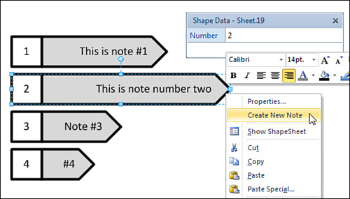
The notes shape has a few...notable...features. Throughout this chapter, you will learn how to implement all of them.
• It has two text blocks: the note and the note number.
• The number is set in a Shape Data field, the note text by selecting and typing.
• When it is stretched, the box around the number stays square, and the point of the arrow maintains consistent pointiness.
• The note text is justified to the end of the arrow, nearer the subject of the notes shape, no matter the length of the shape.
• Right-clicking on Properties opens a convenient Shape Data window for changing the value of Number.
• Right-clicking on Create New Note calls a Visual Basic macro that creates a new notes shape just under the one that you clicked and increments the value of Number.
Using the Developer Ribbon Tab
Before you start, you need to make sure that the Developer tab is visible. Doing so adds some functions that make advanced customization possible. Recall that we mentioned it in Chapter 7, “Working with Data,” where activating it gave us extra fields in the Define Shape Data dialog.
Turn it on by right-clicking a blank area of the Ribbon and choosing Customize the Ribbon. On the right side of the dialog, check Developer in the Main Tabs list.
You see the Developer tab at the far right end of the Ribbon. Examine it, and notice groups of controls, such as Code, Add-ins, Controls, Shape Design, Stencil, and Show/Hide. If you’ve installed the Visio 2010 Software Development Kit, you also see the SDK Tools group, which offers a few more handy tools.
Creating SmartShapes with the ShapeSheet
The ShapeSheet is the spreadsheet-like interface that resides behind every Visio shape. It supports functions similar to Excel, so you can actually program behaviors into shapes without typing lines of code.
Introducing the ShapeSheet
Perhaps you have discovered the mysterious Show ShapeSheet button on the Developer tab, with its big blue, red, and gray table icon that beckons clicking whenever a shape is selected. Click it and the ShapeSheet window appears. This is the key to adding sophistication to your shapes. Figure 11.2 shows the ShapeSheet for a simple rectangle drawn with the Rectangle tool.
Figure 11.2. The ShapeSheet for a simple rectangle. The Protection and Miscellaneous sections are collapsed, and formulas, not values, are showing.
The ShapeSheet is a special-purpose, brightly colored spreadsheet, similar to Microsoft Excel (circa 1992, but I digress...). The ShapeSheet reveals the behind-the-scenes definition of every Visio shape, holding information about its size, position, geometry, formatting, protection, text block, Shape Data fields, and more.
Remember that if you are just drawing with Visio and creating pure graphical symbols, you do not need the ShapeSheet. However, if you want a shape to be smarter than ordinary clip art, you need to understand how it works.
Here’s a list of just some of the things you can do via the ShapeSheet:
• Create smart geometry that behaves well when shapes stretch. In Figure 11.3, you see “smart” and “dumb” versions of three shapes. Notice that the smart versions don’t uniformly stretch. Instead, parts of these shapes maintain proportion, which increases visual consistency and leaves more space for text.
Figure 11.3. SmartShapes that resize intelligently maintain graphic consistency and utilize space better for text. All parts of “Dumb” shapes mindlessly stretch, which looks inconsistent, ugly and wastes space that could be used by text.

• Add custom Actions to the right-click menu and make geometry, formatting, text, and even code respond to them. Figure 11.1 shows two custom actions atop the menu.
• Create multishapes that can change form via right-mouse clicks or Shape Data field values. Imagine a stop-light symbol that can be set to glow red, yellow, or green at the click of a mouse or an electrical switch symbol that closes or opens when on or off right-mouse actions are selected. You saw examples of these in Chapter 6, “Working with Individual Shapes.”
• Store data and calculations in shapes, hidden from users using User-defined cells instead of Shape Data fields.
• Conditionally change the color or other formatting of a shape based on its size, position, or the value of a Shape Data field.
• Display data and calculation results in a shape’s text.
• Protect a shape’s size, position, formatting, text, and other attributes from being edited.
Creating Smart Geometry in the ShapeSheet
Reading about ShapeSheet theory can be duller than a whetstone in a spoon factory. You will retain more information if you fiddle with it in real-life. So let’s jump in and take it for a spin!
Your first task is to build the right side of the notes shape—just the arrow portion. Keeping the point a consistent size is the perfect exercise for understanding the ShapeSheet’s capabilities. Before long, the ShapeSheet will be familiar, and you will have built a functioning, useful SmartShape.
Show Me: Media 11.1—Exploring the ShapeSheet
![]()
Access this video file through your registered Web Edition at my.safaribooksonline.com/9780132182683/media.
Show Me: Media 11.2—Creating the Smart Pointy Box Using the ShapeSheet
![]()
Access this video file through your registered Web Edition at my.safaribooksonline.com/9780132182683/media.
![]() LET ME TRY IT
LET ME TRY IT
Creating a Smart Pointed Box with the ShapeSheet
- Start a new blank drawing, and draw a simple rectangle on the page.
- Show the ShapeSheet for the rectangle. Select the rectangle, go to the Developer tab and click the Show ShapeSheet button in the Shape Design group. Note that this button has a drop-down list that lets you choose from shape, page, or document, so pages and documents have ShapeSheets, too.
- You see a ShapeSheet window similar to the one in Figure 11.2. Note that the ShapeSheet Tools contextual tab appears.
- Switch between formulas and values by clicking the two leftmost buttons in the ShapeSheet Tools tab on the Ribbon. Note how the cells in the ShapeSheet window change between number-and-units such as “4 in.” and formulas such as “Width*0.5” (F5 also toggles formulas and values.)
- Right-click anywhere in the ShapeSheet window and choose View Sections. A list of mysterious-sounding ShapeSheet sections appears. By default, all sections are checked to be visible. However, if you can’t find a section you are looking for later on, be sure to visit View Sections to see if the section has been hidden.
- Resize the ShapeSheet window so that you can see your rectangle and the ShapeSheet at the same time (View, Window, Arrange All).
- Enter different numbers for Width, Height, Angle, PinX, and PinY and watch what happens to your shape. PinX and PinY specify the horizontal and vertical positions of your shape on the page. You can enter different measurement units along with your values, such as 1.25cm, 3.04m, 72pt, and so on.
- Make sure that the ShapeSheet is displaying values and then resize, move, and rotate the shape in the drawing window. Notice what happens to values in the Shape Transform section of the ShapeSheet. What you do in the drawing window shows in the ShapeSheet, and what you do in the ShapeSheet shows in the drawing window.
- Switch to view formulas. Note that all the Geometry formulas are expressed as percentages of width and height. There is no requirement for this, but it is the default.
- In the Geometry 1 section, click in the X2 cell, where it says “Width*1.0.”
- Change the formula to Width*0.5. You can either type in an entire formula or edit the existing one. To get into formula editing mode, double-click a cell, or select a cell and press the F2 key. When you finish changing the formula, press Enter. Your shape and ShapeSheet should look similar to Figure 11.4.
Figure 11.4. Changing the x-location of Geometry1.X2 to be half of the width of the shape. Notice that the point represented by the selected ShapeSheet cell is highlighted with a black square in the drawing window.
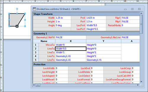
- Notice that Geometry1.X1 and Geometry1.X4 both have the same x-location. They are on the left side of the shape and have the X formula “Width*0.” You can reference one cell from another, similar to the way you do in Excel. Because both cells have the same location, practice creating a reference.
- To create a cell-to-cell reference, click on the Geometry1.X4 cell. Press the equal key; then click on the Geometry1.X1 cell. You should see “=Geometry1.X1” in the X4 cell. Press Enter to finish the formula. Your shape should not visually change, but your ShapeSheet should look exactly like Figure 11.4.
This is also a great way to find out the name of any cell in the ShapeSheet. Select any cell, type “=”, then click another cell. You will see the name of the target cell in the source cell. Press Esc to cancel the editing and leave the source cell unchanged.
- You can add points to your shape from the ShapeSheet. You want to create a pointed box, so you need one more point. This coincides with one more row in the Geometry section.
- Insert a new point just after point 2 in Geometry1. Click on the X or Y cell in row 2. Right-click and choose Insert Row After. A new row appears, Geometry1 now has six rows.
- Change the X formula of Geometry1.X3 to Width*1.0.
- Make a reference from Geometry1.X4 to Geometry1.X2 so that Geometry1.X4 = Geometry1.X2. Figure 11.5 shows how your shape and its ShapeSheet should appear.
Figure 11.5. A rectangle becomes a pointy box thanks to ShapeSheet manipulation. The shapes at the top show how your example currently behaves when resized to different widths.

- Notice that points 2 and 4 control the shape of your arrowhead. They are at the midpoint of the shape, so the head becomes longer when you stretch the shape, as shown in Figure 11.5. You really want the head to maintain a constant sharpness, regardless of the shape’s length. This means that points 2 and 4 need to be a fixed distance from the right side.
- To make the point a fixed size, change the formula in Geometry1.X2 to =Width − 0.25in. Notice that both the top and bottom head points move. The reason is that X4 references X2. Now, if you resize the shape, the point retains a consistent sharpness. You have just replaced a proportional formula with a parameterized, fixed-offset formula.
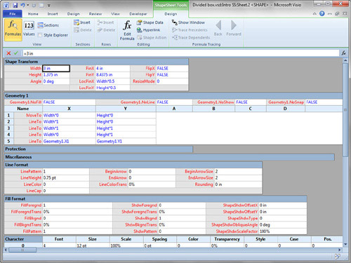
- Notice that if you make the height of your arrow shorter or taller, the point gets sharper or duller. The arrow still needs to be smarter. You can do this by making the length of the head a function of the height of the shape. Change Geometry1.X2’s formula to =Width-Height*0.5. Figure 11.6 shows the final ShapeSheet, along with examples of the shape with various widths and heights.
Figure 11.6. The length of the head of the pointed box is always one-half the height of the body. No matter how long or thick the shape is, the sharpness stays constant. When many differently sized shapes are on the page, there is an uncluttered, visual consistency.

- Save your document as Chapter11.vsd because you will build on it throughout this chapter.
Understanding Visio’s Coordinate System
The coordinates for shapes and pages are the same as you learned in algebra and geometry, namely Cartesian coordinates. The origin is at the lower-left of a shape or page; positive directions are to the right and up.
The Pin of a shape is the same as the rotation point that you see when you mouse over the “lollipop” handle above a shape. In the ShapeSheet, you have seen four cells that define that pin: PinX, PinY, LocPinX and LocPinY cells.
Imagine pinning a note to the wall. The location of the hole made in the wall is defined by PinX and PinY, relative to the lower-left corner of the wall. The location of the hole in the note is defined by the LocPinX and LocPinY. These are relative to the lower-left corner of the note. In this analogy, the wall is the page, and the note is the shape.
Shape developers talk about “local” coordinates and “parent” coordinates. For a shape, LocPinX, LocPinY and Geometry coordinates are local to the shape. PinX, PinY and Angle are relative to the parent: the page, or a containing group.
Budding shape developers are often tripped up by the difference between local and parent coordinates, especially when working with subshapes inside a group.
Controlling Grouped Shapes with the ShapeSheet
You’ve just seen how to smarten the geometry points of a single shape. Next, you try smartening the subshapes within a group.
There are numerous reasons to create grouped shapes. If you need multiple text blocks in a shape, or if you need different line or fill colors and styles, you need to group shapes together. Grouping shapes can also simplify programming by isolating different behaviors in separate subshapes, as you see shortly.
Be warned that once you start adding ShapeSheet smarts to a group and its member shapes, ungrouping becomes very destructive. If you need to alter parts of your group, be sure to subselect the appropriate shapes, or open the group window by right-clicking and choosing Group, Open Group. Ungrouping can blow away a lot of your ShapeSheet work, so don’t do it!
In the next example, you incorporate your pointy box into a well-behaved notes shape. The arrow is grouped together with a number for easy identification. The entire shape exhibits behavior similar to the arrowhead in that the number box doesn’t change when you stretch the whole shape. Figure 11.7 contrasts the way the smartened shape resizes with an unsmart box grouped with the arrow.
Figure 11.7. The smartened notes shape resizes properly in contrast to the behavior you get when a rectangle and arrow are simply grouped together.

Show Me: Media 11.3—Adding Smart Resizing Behavior to Subshapes of a Group
![]()
Access this video file through your registered Web Edition at my.safaribooksonline.com/9780132182683/media.
![]() LET ME TRY IT
LET ME TRY IT
Creating Smart Resizing with Grouped Shapes
- Continuing with Chapter11.vsd, drop a copy of the previously created pointy box on a fresh, empty page.
- Draw a square to the left of the arrow using the Rectangle tool, so you have the basis of the notes shape shown in the top shapes of Figure 11.7.
- Select the rectangle and pointy box, then group them together. Pressing Ctrl+G is the fastest way to do this, but notice the Developer tab has a dedicated Group button in the Shape Design group.
- Select the new group and click the Shape Name button in the Shape Design group on the Developer tab. In the pop-up, you should see that the shape has an ID of 3 and that its name is Sheet.3.
- Subselect each shape in the group and repeat the preceding step. The box on the left should be named Sheet.2, and the arrow should be Sheet.1. If your ids are different, be sure to note which id is for the square and which is for the pointy box. Shape IDs generally reflect the order in which the shapes were created on the page. The sheet notation is useful when you’re referencing ShapeSheet cells in other shapes.
- Before you add smarts to the shape, let’s agree on terminology. Figure 11.8 gives names and shows the conceptual dimensions for each part of the shape, and shows the sheet IDs for each part as well. I will refer to the pieces as Group, Box, and Arrow for the rest of this example, and they will have IDs 3, 2, and 1, respectively. If your shapes have different IDs, you might have to translate some of the IDs in the following steps.
Figure 11.8. The desired dimensions of the subshapes for your smart notes shape. Note that the widths of the Box and Arrow shapes depend on the height of the group.

- Open the ShapeSheet for the group.
- To control the size of the subshapes, it is convenient to add parameters at the group level. This makes it easy to make changes without digging into subshapes. Start by adding user-defined cells to the group. Unlike Shape Data fields, user-defined cells are accessible via the ShapeSheet only, so they remain invisible to end users. Think of them as data fields for developers.
To add user cells, right-click anywhere in the ShapeSheet window and choose Insert Section.
- In the Insert Section dialog, check User-Defined Cells. The User-defined Cells section appears in the ShapeSheet, with one row named User.Row_1. You can freely rename Row_1 to something more meaningful, but you can only use numbers, letters and the underscore symbol.
- The notes shape needs four user cells, so add three more. To add User rows, right-click in any cell of Row_1 and choose Insert Row. You can quickly repeat this action two more times by pressing F4.
- You change the name of user cells in the same way that you edit cell formulas. Change the names of your rows and enter formulas in the Value column so that your User section looks like this:
User.BoxWidth = Height
User.BoxHeight = Height
User.ArrowWidth = Width - Height
User.ArrowHeight = HeightNote, you get “User.” for free, don’t type this when changing row names! You have now defined the important size parameters for the subshapes.
- The four parameters are currently calculating away in silent anonymity because no other cells reference them. Let’s hook up the Box subshape to the first two. Start by subselecting the Box and showing its ShapeSheet.
- Enter these formulas in the Shape Transform section of the Box shape. Note what happens to the shape after each change:
Width = GUARD(Sheet.3!User.BoxWidth)
Height = GUARD(Sheet.3!User.BoxHeight)
LocPinX = GUARD(0)
LocPinY = GUARD(0)
PinX = GUARD(0)
PinY = GUARD(0)The width and height of the box refer to the user-defined parameters stored in the group’s ShapeSheet. Note the cross-sheet referencing syntax for these two formulas: Sheet.ID + exclamation point + cell-name.
User-defined rows have two cells: Value and Prompt. The full names of the cells are, for example: User.BoxWidth.Value and User.BoxWidth.Prompt. Since the Value cell is the default, Visio lets you use more compact notation and leaves “.Value” off, as we did in our formulas above.
The pin is located at the center of a shape by default. You can reduce calculation by moving it to the lower-left corner, which is point 0,0. The formulas you just entered cause the LocPin to be in the lower-left corner of the box, and its Pin to be in the lower-left corner of the group. Zeros across the board! Note that this changes the rotation point of the shape to the lower-left corner as well. But we won’t be rotating the box, so this is just fine.
The GUARD function prevents users from accidentally moving the shapes and breaking the smart formulas. It also tells Visio to preserve the formulas when the shape is copied.
- Now you’re ready to link the Arrow to the Group’s parameter cells. Subselect the Arrow shape and show its ShapeSheet.
- Enter these formulas in its Shape Transform section, as you did in the previous steps:
Width = GUARD(Sheet.3!User.ArrowWidth)
Height = GUARD(Sheet.3!User.ArrowHeight)
LocPinX = GUARD(Width)
LocPinY = GUARD(0)
PinX = GUARD(Sheet.3!Width)
PinY = GUARD(0)Similar to what you did with the Box, these formulas simplify the positioning calculations by moving the LocPin to an edge—this time to the lower-right corner of the arrow and of the group.
If you resize your group, the Box should stay square, the point of the Arrow should maintain its shape, and there should be no gaps between the two subshapes.
- Be sure to save your file as you work. While the notes shape is now much smarter, you’re still not done with it!
Linking Subshape Text to Shape Data Fields
By linking the size and position of the subshapes to user-defined parameters, our notes shape behaves graphically correct when resized. Now we need to attend to the text. The text in the Box should be linked to a number field in the group. In the next exercise, you create a Shape Data field in the Group shape, then refer to it from the Box to create data-linked text.
![]() LET ME TRY IT
LET ME TRY IT
Linking Shape Data to Text on a Subshape
- Create the Number field for the notes shape. Right-click on the Group shape and then choose Data, Define Shape Data. In the dialog, set both the Name and the Label fields to Number. Choose a data type of Number in the Type field, as shown in Figure 11.9.
Figure 11.9. Creating the Number field.

- Open the ShapeSheet for the Group. Scroll down until you see the Shape Data section. You should see one row, with the row name Prop.Number. Number is what you typed in the Name field in step 1. Prop comes from the fact that Shape Data fields used to be called Custom Properties. You should also see Number in the Label cell. The value for the Type cell should be 2, which corresponds to the number data type you chose in the dialog.
- Double-check the name of the Group. If you are working with a copy of the shape, it might have a different ID than Sheet.3. Select the Group and then click Shape Name on the Developer tab. Make a note of the ID.
- Link the text of the Box shape to this new field. Subselect the Box and then press F2 to change to text edit mode. Remove any text that might be in the box.
- From the Insert tab, click Field in the Text group. Notice that Shape Data is selected, but the list of fields on the right is empty. The reason is that the Box doesn’t have any Shape Data. The Number property belongs to the group. Visio isn’t clever enough to offer parent shapes’ Shape Data fields for you to insert, so we have to do a bit of extra work
- Click Custom Formula at the bottom of the Category list. The Custom Formula text box just below becomes active.
- In the Custom Formula text box, start typing the sheet ID for the group. While your group is probably named Sheet.3, the shape in Figure 11.10 has an ID of 16 just to illustrate that ids can be different. As I start typing Sheet.16, and then type an exclamation point, see how IntelliSense pops ups and helps with possible cells in the group’s ShapeSheet? You can continue typing “Prop” and the possibilities narrow to just Sheet.16!Prop.Number.
Figure 11.10. Linking subshape text to the parent group’s Shape Data by inserting a custom field.
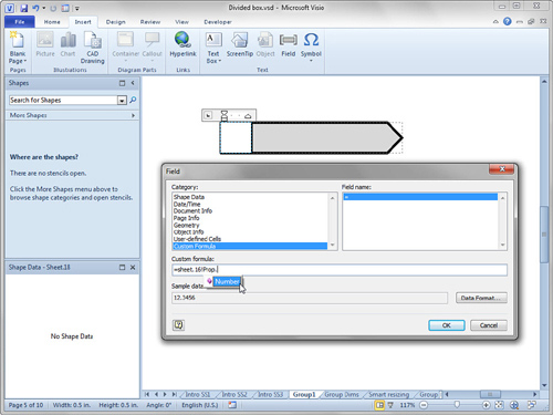
- Once the whole formula is entered (=Sheet.16!Prop.Number), click OK. The subshape’s text should now be linked to the field. (Remember, your formula might have been =Sheet.3!Prop.Number.)
- Show the Shape Data window if it isn’t visible. The easiest way is to right-click any shape and then choose Data, Shape Data.
- Select the notes shape and then change the value of the Number field. The text in the Box should update.
- Subselect the box and open its ShapeSheet window. Scroll down until you see the Text Fields section. You should see one row, with a Value cell that shows the same Sheet.16!Prop.Number (or Sheet.3...) formula that you just entered in the dialog.
Modifying the Text Block Using the ShapeSheet
If you select the notes shape and then start typing, you see that the text is centered and that the text block is as wide as the whole shape. This text belongs to the group itself, not to the box nor the arrow. You really want the text block to match the width of the arrow, and it should be right-aligned so that the text is aligned with the point of the arrow.
You could use the Text Block tool to make the text block less wide, but it would still size proportionally when we stretched the shape and wouldn’t line up properly. The text block needs to be exactly as wide as the arrow subshape. To do this requires the ShapeSheet.
![]() LET ME TRY IT
LET ME TRY IT
Modifying the Text Block in the ShapeSheet
- Select your notes shape and then type some text. You should see center-aligned text, and the number in the Box should be unaffected.
- Right-align the text by selecting the notes shape, going to the Home tab, and clicking the Align Right button in the Paragraph group. Notice that when you do this, the number also is right-aligned. When you apply formatting to a grouped shape, all subshapes receive that formatting, too. Not always desirable.
- Press Ctrl+Z to undo Step 2.
- To right-align just the text for the group, select the group and then press F2. The text that you typed should be highlighted. Now you can click the Align Right button, and it affects only the group’s text block, not those of the subshapes. A sneaky trick, but it works!
- The text block is still as wide as the entire group, and the right alignment has sent the text a bit far into the point of the arrow. You need to edit the text block in the ShapeSheet, so show the ShapeSheet window for the Group.
- To control the size of the text block, you should edit cells in the Text Transform section. By default, this section doesn’t exist, however, because shapes use a default text block that exactly matches the size of the shape. To insert the Text Transform section, right-click anywhere in the ShapeSheet and then choose Insert Section.
- Check Text Transform in the dialog and then click OK. The Text Transform section is added to the ShapeSheet. Scroll to the lower-half of the ShapeSheet to find it. Here you can control the size, position and rotation of the text block via ShapeSheet expressions.
- Scroll down until you see the newly inserted Text Transform section and then modify three of the formulas as follows:
TxtWidth = GUARD(User.ArrowWidth-Height*0.5)
TxtPinX = GUARD(Width-Height*0.5)
TxtLocPinX = TxtWidthThe Text Transform cells govern the size and position of the text block inside a shape. Note how the TextPin and TextLocPin cells are analogous to Pin and LocPin cells of the shape. It is as if the Text is a subshape inside a group.
TxtWidth is the width of the actual text block. The formula above makes it as wide as the body of the Arrow minus the width of the arrow tip. This keeps the text from getting scrunched inside the point. The text’s local pin x is on the right at TxtWidth. The text’s pin is positioned where the head of the arrow begins, at Width - Height*0.5.
- As a convenience, you can configure the shape so that double-clicking enters text edit mode. To do this, select the Group and then click Behavior in the Shape Design group on the Developer tab.
- Click the Double-Click tab in the Behavir dialog. Check the Edit Shape’s Text radio button and then click OK to finish. Now double-clicking your notes shape will take you straight to the text.
- For some final spit-and-polish, protect the subshapes from being selected. This reduces confusion for users of your shape and also protects the subshapes from being inadvertently altered.
- Select the Group and click the Behavior button again. In the lower-right corner of the dialog is the Selection drop-down list. Select Group Only from this list and then click OK. The subshapes can no longer be selected. If you need to alter the subshapes, you can still open the group by right-clicking and then choosing Group, Open Group, but end-users are unlikely to do this.
Adding Right-Click Actions to the SmartShape
The notes shape is still missing the two right-click actions shown in Figure 11.1: one to open a Shape Data dialog and one to call some custom code. You can set up both of them now and then transition into the section about VBA programming to make the second item actually work.
Adding Actions Using the ShapeSheet
- Open the ShapeSheet for the notes shape.
- Insert an Actions section and make sure it has two rows in it. This is similar to the procedure for adding user-defined cells. Action rows are used to add custom right-click menu items to a shape’s context menu.
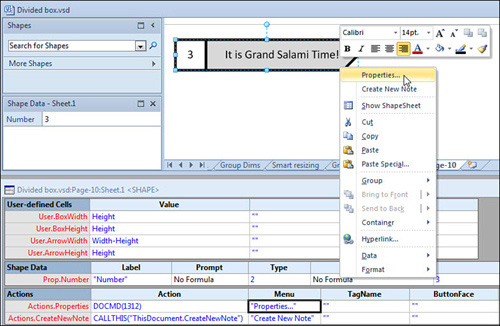
- Name the first action row Properties and the second one CreateNewNote.
- Set the Action and Menu cells for the rows as follows:
Actions.Properties.Action = DOCMD(1312)
Actions.Properties.Menu = "Properties..."
Actions.CreateNewNote.Action =
CALLTHIS("ThisDocument.CreateNewNote")
Actions. CreateNewNote.Menu = "Create New Note"The Menu cells expect strings. If you have trouble, make sure there are double quotation marks on both sides of the text. Whatever you type in the Menu cell will show in the right-click menu.
The Action cell does the actual work. Actions can be performed in a number of ways such as setting ShapeSheet formulas, calling Visio functions, or invoking macros or add-on code. The first action uses the DOCMD ShapeSheet formula to call command 1312. This is the command id for showing the Shape Data pop-up window. The second Action uses the CALLTHIS function to access a VBA macro that you will write later on.
Figure 11.11 shows how the Actions section for the notes shape should look.
Figure 11.11. Actions defined in the ShapeSheet appear when right-clicking the shape.
- Close the ShapeSheet and then right-click the modified shape and choose Properties. A pop-up version of the Shape Data window should appear. Here, you can edit the Number field.
- If you choose Create New Note from the right-click menu, nothing happens. This action calls macro code that you create in the next section.
That wraps up the ShapeSheet portion of this project, and you’ve achieved quite a lot! You’ve created a smart-sizing arrow. You grouped the arrow with the number box and created resizing smarts that keep the box square, and the arrow using the remaining space. You linked the box’s text to a Shape Data field in the group, and you configured the notes text so that it is nicely aligned within the arrow. To top it all off, you added custom right-click actions that show Shape Data and call VBA macros. Phew! Now it’s time to write that macro, and then discuss ways to deploy your SmartShape in a stencil with a template.
Introducing Automation and VBA Code
You’ve seen that the ShapeSheet is a nifty tool you can use to turn your Visio shapes into intelligent graphical mechanisms. For some tasks, using a programming language is more appropriate. Luckily, Visio has a built in development environment, just like other applications in the Microsoft Office suite.
Visual Basic for Applications, or VBA, is a programming language similar to BASIC, which has been around for eons and is renowned for its friendly, English-based syntax.
Exploring the VBA Development
Because the VBA environment is built in to Visio, you can start using it in a matter of seconds. It is a wonderful tool for experimenting with Visio’s object model, properties and methods, and offers a quick way to get your developer feet wet, so to speak.
Exploring the VBA Development Environment
- Start with the drawing in which you’ve been creating the notes shape.
- Create a few copies of the notes shape and perhaps draw some rectangles on the page as well. Make sure that the shapes have text in them.
- Start the VBA environment. In the Code group on the Developer tab, click the big Visual Basic button. Or you can do what I do many times every day: press Alt+F11. The Microsoft Visual Basic for Applications development environment appears in its own application window, separate from Visio
- Make sure the Project Explorer and Immediate windows are both visible. You can turn them on via the View menu. The Project Explorer is usually on the left, and the Immediate window is at the bottom.
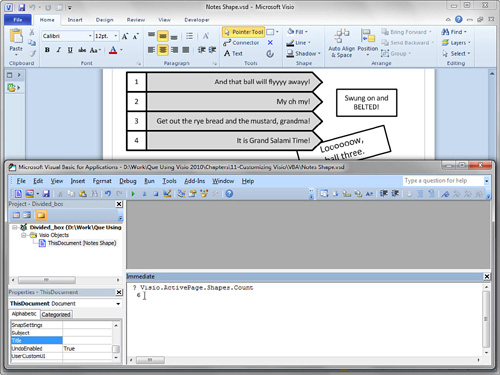
- The Immediate window is great for exploring bits of automation code. You can type single lines of code into the Immediate window and learn Visio VBA bit by bit. For example, in the Immediate window, type
? Visio.ActivePage.Shapes.Count
Then press Enter. The number of shapes on the active Visio page is printed on the next line, as shown in Figure 11.12.
Figure 11.12. Using the Immediate window to query Visio. In this window, “?” is shorthand for “Print” and instructs VBA to output the result of the following statement.
- You can get the name of the current page by entering the following:
? Visio.ActivePage.Name
- Query Visio for the number of pages in your document by typing
? Visio.ActiveDocument.Pages.Count
- Try outputting the text from various shapes by entering
? Visio.ActivePage.Shapes.Item(1).Text
You can change the number in the parentheses to get the nth shape on the page.
- Switch back to Visio quickly by pressing Alt+Tab. This is a good shortcut because you need to frequently switch between VBA and Visio.
- Draw two rectangles on the page and make sure they are selected.
- Back in VBA, instruct Visio to connect the two rectangles as follows:
ActiveWindow.Selection(1).AutoConnect ActiveWindow.Selection(2),
visAutoConnectDirDownNote that there is no ? at the beginning of this statement. You aren’t asking for an output; you are telling Visio to do something. In this case, to connect the first selected item to the second, in the down direction. Note that you used shorthand by not typing out Item. Instead of Selection.Item(1), you can type Selection(1). Figure 11.13 shows the result.
Figure 11.13. Connecting two selected shapes using a code snippet in the Immediate window.

- The Immediate window is fine for testing bits of code, but eventually you will need several lines of code, and you will want to save them. You can create procedures that will be saved with the document. Let’s make a simple one now.
Double-click on ThisDocument in the Project Explorer. A blank white area occupying the bulk of the VBA window appears, along with a blinking text cursor. This is the code module called ThisDocument.
- In the code window, type Public Sub HelloVisio and press Enter. VBA adds empty parentheses to the end of your line and closes the procedure with the line End Sub.
- Between the two lines, type the following code so that your subroutine looks like this:
Public Sub HelloVisio()
Dim s As String
s = "Page: " & Visio.ActivePage.Name
s = s & " has " & Visio.ActivePage.Shapes.Count
s = s & " shapes."
MsgBox s
End SubA few notes about this: s is a variable, which you declared to be a string in the first line, using the Dim statement. You then built s into a message by concatenating bits of text. For strings, you use the & operator to add chunks of text together. So ”Visio” & “Guy” = “Visio Guy”. Finally, you invoke a pop-up message box to display the text stored in s. The code in HelloVisio will pop up a message displaying the name of the active page, and the number of shapes it contains.
- Save your document. Click the disk icon in the top-left corner of the VBA window, and your code will be saved inside of the Visio document. Having two separate application windows for Visio and VBA makes it feel like the code is separate from the diagram, but that is not the case. Code and diagram are saved in the same file, and you can save from Visio or from the VBA environment.
Note that Visio doesn’t have a central repository for macros like Word does—there is no “Normal.dot” for holding code that can be accessed from all documents. However, stencils can also have VBA code, which can serve a similar purpose.
- Run your new sub. First, place the cursor anywhere inside your new block of code. Then click the Play button in the toolbar; it’s the one with the right-pointing arrow and shows the ToolTip Run Sub/User Form(F5). I find it much easier to just press F5 to run code. A message box pops up declaring something like “Page-1 has 12 shapes.” Try adding and deleting shapes from the active page and re-running your subroutine.
You can also run macros from Visio by clicking the Macros button on the View and Developer tabs.
- You can also send information from a subroutine to the Immediate window. This lets you analyze a Visio diagram programmatically. Add this procedure after the HelloWorld subroutine:
Public Sub ListShapes()
Dim i As Integer
Dim shp As Visio.Shape
For Each shp In Visio.ActivePage.Shapes
i = i+1
Debug.Print i & ". " & shp.Text
Next
End SubDebug.Print instructs VBA to output information to the Immediate window.
- Place your cursor inside ListShapes and run the procedure. Figure 11.14 shows a possible result.
Figure 11.14. Sub ListShapes outputs the text of every shape on the page to the Immediate window. Because item 7 lists no text, it must be the connector, since it is the only shape in the drawing that has no text!

Using the Macro Recorder to Generate Code
The Immediate window allows you to quickly try bits of code, and the IntelliSense drop-down lists make it even easier to discover functions for Visio objects.
Visio also has a macro recorder that generates VBA code while you manipulate objects onscreen. You can then modify and reuse this code. Using the recorder is a great way to learn how to program Visio, too.
Recording a Macro
- Start with a page that contains the notes shape.
- Click the macro recording button located at the bottom left of the main Visio window. The icon is a rectangle with a blue header and red dot. The Record Macro pop-up appears.
- Leave the suggested name—Macro1—and click OK to begin recording.
- Duplicate the notes shape by Ctrl+dragging a new copy.
- Click the stop recording button at the bottom of the screen. This is the same button as the record macro, but now it has a blue square for an icon.
- Switch over to VBA and locate the Modules folder in the Project Explorer on the left. Expand the Modules folder. The NewMacros code module appears.
- Double-click on NewMacros. The code window on the right should display your new macro called Sub Macro1().
- The code for duplicating your shape is in the subroutine Macro1, as shown in Figure 11.15. You can copy this and paste it into your own Subs or slightly modify it. The sky’s the limit!
Figure 11.15. Overly verbose macro recorder code for duplicating a shape.
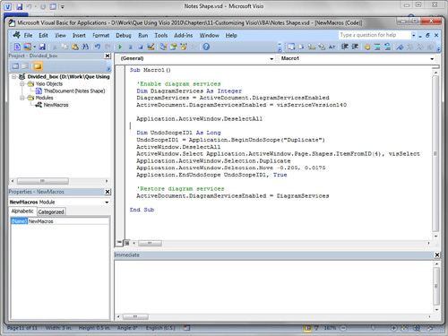
Here are a few things to note about the code in Figure 11.15 and macro recording in general:
• Two lines start with an apostrophe and appear green in the VBA editor. These are comments that have no effect on how the code runs, but remind humans of the intent of the code. Comments are a good thing. Use them to document the purpose of your code blocks.
• When you record macros in Visio 2010, six lines are added regarding DiagramServices that aren’t really related to the actions you performed. In Figure 11.15, these are the first four lines and the last two lines. Don’t worry about understanding them right now.
• The macro recorded the selection of a particular shape. In Figure 11.15, find the line that ends with ...ItemFromID(4), visSelect. (It’s the longest line.) If you try to reuse this macro for a page that doesn’t have a shape with ID=4, the code fails. Note: this ID is the same ID that we have talked about earlier when referring to shapes in ShapeSheet cells.
• To make a macro that duplicates selected shapes and moves them a specific amount, just delete this line plus the two lines that end with ...DeselectAll.
• Visio wraps the macro in an “undo scope.” This creates a named set of commands that can be undone in one action. Even if the code performs many operations, one undo restores your drawing to its original state. The name of the undo scope is shown in the Undo/Redo buttons at the top left of the Visio window.
• Macro code isn’t perfect. You’ve just seen that Visio inserted a bunch of extra stuff like Diagram Services and undo scopes that muddy the code. Plus, selecting a shape by ID is not something you can easily re-use without modification. So use the macro recorder to learn which commands are needed for particular operations. However, be prepared to clean up the code that is generated, and modify it for general use.
Calling VBA Code from a SmartShape
Now that you’re familiar with the VBA environment and basic subroutines, it’s time to connect the notes shape with some useful code.
![]() LET ME TRY IT
LET ME TRY IT
Creating a VBA Subroutine That Can Be Run from a Shape
- Start with a new page, and copy a finished notes shape to it.
- If you look at the ShapeSheet for the notes shape, you see that the second Action row looks like this:
Actions.CreateNewNote.Action=CALLTHIS("ThisDocument.CreateNewNote")
The CALLTHIS ShapeSheet function looks for the sub CreateNewNote in the ThisDocument VBA module. We know where ThisDocument is, we just need to add CreateNewNote to it.
- Open the VBA interface and bring up the ThisDocument code module.
- Create the declaration of a sub that can be accessed from a shape. Subs that work with CALLTHIS need to have a shape variable as an argument. Type this code:
Public Sub CreateNewNote(ByRef shp As Visio.Shape)
End Sub - You can quickly test if the shape is successfully getting to the sub by adding a simple message box line:
Public Sub CreateNewNote(ByRef shp As Visio.Shape)
MsgBox "Hi, my name is CreateNewNote!"
End SubNow you can test the code from the shape. Don’t run this sub from VBA, as you did previously. Instead, return to Visio, right-click the notes shape, and choose the second item. The message box appears, showing the test message you just coded.
- Now you’re ready to code the full CreateNewNote sub. It’s not a lot, just 15 lines, including five comments. Pay attention to the comments because they explain the purpose of each code block.
Public Sub CreateNewNote(ByRef shp As Visio.Shape)
' Get the location and height of the existing shape:
Dim shpNew As Visio.Shape
Dim px As Double, py As Double, h As Double
px = shp.Cells("PinX").ResultIU
py = shp.Cells("PinY").ResultIU
h = shp.Cells("Height").ResultIU
' Drop a copy of the shape onto the page:
Set shpNew = shp.ContainingPage.Drop(shp, px, py - h)
' Increment the number field:
Dim n As Integer
n =
shp.Cells("Prop.Number").ResultInt(Visio.VisUnitCodes.visNoCast, 0)
' Set the new shape's number to be one more than the old:
shpNew.Cells("Prop.Number").ResultIU = n+1
' Set the new shape's text:
shpNew.Text = "Notes shape, number = " & n+1
End Sub - Return to Visio and run the code by right-clicking the notes shape. You should get a new copy of the shape directly below the shape you clicked. The Number field should be incremented by one, and the text should be changed to reflect the new index.
An interesting feature of the CreateNewNote subroutine is the code used to get and set values from the ShapeSheet. The Cells method takes a string argument that matches the name of a cell in the ShapeSheet. In this way, shp.Cells gives you access to the entire ShapeSheet.
Many budding Visio developers scour the SDK documentation looking for the properties Width, Height, Geometry1X1, to no avail. Cells is the key they miss. When you have a cell object, you can ask for its value in “internal units” by using ResultIU. Internal units in Visio are inches. If you use a different measurement system, you can use Result instead. For example, shp.Cells(“Width”).Result(“cm”). You can also get a cell’s formula—for example, shp.Cells(“Geometry1.X1”).Formula.
Tell Me More: Media 11.4—Extending the CreateNewNote Subroutine
![]()
Access this video file through your registered Web Edition at my.safaribooksonline.com/9780132182683/media.
Distributing Templates and Stencils
Now that you have a super-smart notes shape that has custom ShapeSheet behavior and is linked to a macro, it’s time to share it with your team...or the world! There are several ways to go about this; let’s explore them.
Creating a Template with a Document Stencil
Most Visio templates open several stencils that are separate files. This is great if a template needs access to lots of shapes and stencils. However, for solutions that need only a few master shapes, it makes sense to put these masters in the local document stencil.
Recall from Chapter 2, “Working Around the Diagram,” that the document stencil is part of the Visio document, so if you choose this route, you only have to distribute one file: the template itself.
![]() LET ME TRY IT
LET ME TRY IT
Creating a Template with Shapes in the Document Stencil
- Open a copy of your notes shape file, Chapter 11.vsd, to serve as your new template. Note that the Open button in the Open dialog within Visio is actually a drop-down list, from which you can choose “Open as Copy.”
- Show the document stencil for the drawing. In the Shapes window, choose More Shapes, Show Document Stencil. A blank stencil should appear with the title Document Stencil. This is the collection of master shapes that belong to the drawing file itself.
- Copy the latest, final version of the notes shape, then right-click in the document stencil window and choose Paste. The notes shape magically appears in the stencil as a new master, with the name Master.1. You can also drag and drop to the Document Stencil.
- “Master.1” is dull and non-descriptive, so rename the master. Select Master.1 and press F2 to edit the text. Or, right-click the master and choose Rename Master. Change the name to “Notes shape.”
- Clean up the drawing file by removing extra pages and deleting shapes from pages. Configure the page size and orientation as desired. Add backgrounds, title blocks, and company logos that make the template more useful.
- Clean up the VBA code. The template only requires the code for CreateNewNote, so that the notes shape will function properly. Open the VBA editor and remove all code except for the CreateNewNote subroutine. Be sure to look in the Project Explorer for modules you might have created by the macro recorder. For example, right-click the NewMacros item under Modules and choose “Remove NewMacros.” Click No to not export before deleting.
- Save the file as a template. Go to File, Save As. In the dialog, enter the filename Notes Shape Template 1, and in the Save as Type box, choose Template (*.vst).
To distribute this template to your team, you have only one template file to send around instead of a template plus a stencil.
When users double-click on Notes Shape Template 1.vst in Windows Explorer, Visio opens an unsaved copy of the drawing, and the Notes shape master is visible in the document stencil.
Dealing with Macro Security Warnings
Because the template contains VBA code, you see a warning alerting you to the presence of macros and asking you to enable or disable them. You can change the level of macro security by visiting File, Options, Trust Center, Trust Center Settings, Macro Settings. Users that have the highest setting will not see any warning about your macros, and the CreateNewNote code won’t run at all.
Rather than loosen your macro security settings, you can also specify certain directories on your system that contain trusted code. To add a trusted location, visit File, Options, Trust Center, Trust Center Settings, Trusted Locations, and then add the path. Files with VBA macros stored in a trusted location do not present a macro security alert, and will run just fine. Perhaps members of your team could create a trusted folder called “My Team” and place macro-enabled templates and stencils from fellow employees in this folder.
Displaying Templates in Choose a Template
Usually, you start new drawings by visiting the template gallery at File, New, Choose a Template. It’s nice to have your custom templates can show up in this screen as well. You can inform Visio of special folders that contain your content, so that your custom templates appear in the Backstage area.
Go to File, Options, Advanced. Scroll down to the bottom of the options and click the File Locations button. In the dialog that appears, enter the path where you would like to store your custom templates, as shown in Figure 11.16.
Figure 11.16. Specifying custom template paths.

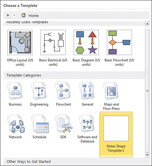
You can have multiple locations for custom templates. Just separate multiple paths with semicolons. After you click OK, you need to restart Visio for the changes to take effect, but thereafter your custom template will appear in the new gallery, as Figure 11.17 shows.
Figure 11.17. A custom template appears in the template gallery. Note the absence of a preview. Show Me 11.5 discusses how to add previews.
Show Me: Media 11.5—Displaying Custom Templates in Choose a Template with Custom Preview Images
![]()
Access this video file through your registered Web Edition at my.safaribooksonline.com/9780132182683/media.
Creating a Separate Stencil for Shape and Code Delivery
If you want to use the notes shape with any number of drawing types, you should distribute a stencil rather than a template.
Also, because the sample shape has supporting VBA code, it makes a lot of sense to distribute a stencil to contain both the shape and shape-related code.
Having VBA code in a template has the drawback that the code is copied and saved with every drawing that is created. This is not only wasteful, but makes updating the code nearly impossible. And VBA code can’t be stored in a shape. Putting code in a stencil alleviates the problem of having copies of your code saved with every drawing, but the stencil must be open for the code to run. This is hard to guarantee, so your users must be informed of this.
Creating a new stencil to hold the notes shape is easy enough, but copying the VBA code to the stencil is a bit trickier. Let’s look at both of these procedures.
![]() LET ME TRY IT
LET ME TRY IT
Creating a New Stencil
- Start Visio with no documents open.
- On the Developer tab, click the New Stencil button. A new, unsaved stencil appears with a title such as Stencil1.
- Retrieve a copy of the notes shape. Open Chapter 11.vsd and copy the shape.
- If the drawing window obscures the stencil window, you can tile them by going to the View tab and clicking Arrange All.
- Switch back to the stencil by clicking its caption, or by clicking Switch Windows in the bottom right of Visio’s main window or by pressing Ctrl+Tab until you see the stencil.
- Right-click in the stencil window and paste. The notes shape becomes a new master, with the name Master.1.
- Rename the master to Notes shape.
- Save the stencil as Notes Shape Stencil.vss.
When you copy the code from the drawing to the stencil, you can’t put it in ThisDocument; you have to put it in a different module. Because of this requirement, you also have to update the ShapeSheet formula that calls the code.
![]() LET ME TRY IT
LET ME TRY IT
Copying VBA Code to a Stencil
- Starting where you left off with Notes Shape Stencil.vss and Chapter 11.vsd open, and bring up the VBA environment.
- In the Project Explorer, note that there are two projects: one for the document and one for the stencil.
- Open the ThisDocument code module for Chapter 11 and copy the subroutine CreateNewNote.
- Right-click on the Project Explorer node for the stencil and choose Insert, Module. A new item named Module1 should appear in the Modules folder, as shown in Figure 11.18.
Figure 11.18. A new item appears in the Modules folder.

- Double-click Module1 to bring up its code window and then paste the copied code into the window.
- Note the project name for the stencil. In Figure 11.18, it is Notes_Shape_Stencil. You need this name for modifying the ShapeSheet formula in the Notes shape master.
- Back in Visio, close Chapter 11.vsd.
- Because the code for the shape now resides in Module1 of the Notes_Shape_Stencil project, you have to make a slight change to the Action formula for the notes shape. Double-click the Notes shape master to open its editing window.
- In the master-editing window, show the ShapeSheet for the notes shape.
- Change the Actions formula as follows:
Actions.CreateNewNote =
CALLTHIS("CreateNewNote","Notes_Shape_Stencil")Notice that ThisDocument. is removed from the first argument and that the stencil’s project name is added as a second argument.
- Close the master-editing window.
- Save the stencil.
- Open a new drawing, drag the notes shape into it, and test that the code works by right-clicking the shape.
Creating a Template with a Separate Stencil
Of course, you might still want to distribute a template but with the notes shape stencil and supporting code. In this case, you use a separate stencil that contains the VBA code, as you just created. Then you open a new, blank drawing (with no code in it), add backgrounds, titles, logos and other pre-drawn graphics, then open the Notes Shape Stencil via More Shapes. Save the document as a template, and you’re done!
To deploy, you send both files: the stencil and template. Users can place both files in a directory and set up the templates file location to point to this directory so that the template appears in the New screen.
Alternatively, the stencil can be placed in the My Shapes folder where it is easily opened for use with other drawings. The template expects the stencil to be in the same folder, but Visio is smart enough to searches through My Shapes as well, if the stencil isn’t found in the same directory as the template file.
Locating Visio Development Resources
If you enjoyed the exercises in this chapter, are fired up about Visio solution development and are thirsting for more, I’ll show you where to drink.
Your first stop is to get the Visio 2010 Solution Development Kit (SDK). You can download it from Microsoft. The easiest way to find it is to search for “Visio 2010 SDK.”
The SDK contains plenty to read, code samples in VBA, VB.NET, C# and C++ that you can copy, modify and learn from, as well as ready-to-go tools to help you with repetitive or difficult tasks. When you install the SDK, the tools even show up on the Developer Ribbon tab, in the SDK Tools group.
Books About Visio Development and Customization
Of course, nothing beats curling up on the couch on a cold rainy day, with a cup of coffee and a real, live book about computer programming. (Yes, I’m from Seattle.) Although there are plenty of books about Visio, only a handful deal with developer-specific issues. Here are the top entries:
• Visio 2003 Developer’s Survival Pack by Graham Wideman
• Visualizing Information with Microsoft Office Visio 2007 by David J. Parker
• Microsoft Visio 2010 Business Process Diagramming and Validation by David J. Parker
• Developing Microsoft Visio Solutions by Microsoft Press and Microsoft Corporation
The Visio 2003 Developer’s Survival Pack is getting long in the tooth, but it is still relevant. If you’re eager to learn the fine details of shape creation and Visio automation, it is worth a look. Because Visio 2010 introduced major new customization possibilities, you should keep an eye on the “What’s New” section of the developer help that comes with the SDK. But the Pack still has tons of good information to offer.
David Parker’s Visualizing Information with Microsoft Office Visio 2007 combines both power-user tips and developer information in a single book. It covers in-depth the data graphics features that were introduced in Visio 2007 and are still a big part of Visio 2010. This book helps fill in a lot of the gaps left open by the Survival Pack’s age.
Developing Microsoft Visio Solutions is available online (http://msdn.microsoft.com/en-us/library/aa245244%28v=office.10%29.aspx) from MSDN. Although it was written for Visio 2002, it still contains plenty of relevant information.
Websites About Visio Development and Customization
Plenty of websites and newsgroups contain information about the ShapeSheet and programming Visio. Using a search engine is a good way to find resources, especially if you use Visio-specific terms, such as ShapeSheet, “SmartShape” or “PinX.” Here’s a short list of some good places to start.
• Visio Guy (http://www.visguy.com)
• Visio Guy Forum (http://www.visguy.com/vgforum)
• John Marshall’s Visio Information (http://visio.mvps.org/)
• David Parker’s Visio blog (http://davidjpp.wordpress.com/)
• John Goldsmith’s visLog (http://visualsignals.typepad.co.uk/vislog/)
• Visio Insights (http://blogs.msdn.com/b/visio/)
With the exception of Visio Insights, all these websites are run by Visio MVPs (Microsoft Most Valuable Professionals) who are knowledgeable Visio experts but not employed by Microsoft. Visio Insights is the official blog of the Microsoft Visio product team and has lots of good “insider” information.
Summary
I hope you found this whirlwind tour of Visio customization useful and inspiring. Although this chapter covers a lot of information, even more has been left out! Nevertheless, you learned about the ShapeSheet and how you can manipulate geometry to behave more intelligently, add custom actions to shapes, and link text to Shape Data.
You saw how to generate VBA code using the macro recorder, extend the utility of shapes by creating subroutines that manipulate them, and call the code from shapes themselves.
Finally, this chapter discussed opportunities for deployment, including distributing shapes with stencils and templates, and the issues that come up with VBA code stored in documents.