Chapter 9. Configure and Manage Virtual Networks
This chapter covers the following topics:
• vSphere Distributes Switches (vDS)
• Configure and Manage Other Networking Features
• Manage Host Networking with vDS
This chapter addresses VMware 2V0-21.20 Exam Objectives 1.4, 1.7, 1.7.1, 1.7.2, 1.7.3, 1.7.4, 4.2, 4.14, 5.4
This chapter concentrates on how to steps to configure and manage different network objects in vSphere 7. These steps can be useful in creating the different networking objects that you will encounter in the VCP exam. There are a number of objectives that will be covered in detail.
“Do I Know This Already?” Quiz
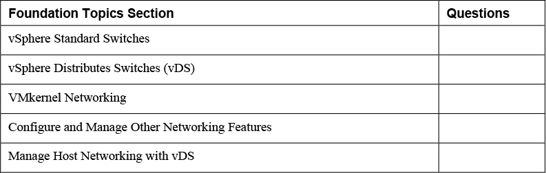
The “Do I Know This Already?” quiz allows you to assess whether you should study this entire chapter or move quickly to the “Exam Preparation Tasks” section. Regardless, the authors recommend that you read the entire chapter at least once. Table 9-1 outlines the major headings in this chapter and the corresponding “Do I Know This Already?” quiz questions. You can find the answers in Appendix A, “Answers to the ‘Do I Know This Already?’ Quizzes and Review Questions.”
Table 9-1 ”Do I Know This Already?” Section-to-Question Mapping
1. You want to connect physical adapters to an existing vSphere Standard Switch. Which one of the following steps should you take?
a. Select Manage Physical Adapters and click the Add Adapters button.
b. Select VMkernel Adapters.
c. Create a port group, then add the adapter.
d. Create an uplink port group, then add the adapter.
2. You are assigning a VLAN ID to a standard port group. What is the acceptable range?
a. 1 - 4094
b. 0 – 4095
c. 0 - 4094
d. 1 - 1095
3. You are modifying an existing vDS. Which of the following options are not available on the General settings page?
a. Name
b. Number of uplinks
c. Network I/O Control
d. VLAN ID
4. You are modifying an existing vDS. Which of the following options are not available on the Advanced settings page?
a. Traffic Filtering and Marking
b. MTU
c. Multicast Filtering Mode
d. Discovery Protocol
5. You are adding a VMkernel adapter to a vDS. Which one of the following settings is not available?
a. SR-IOV
b. MTU
c. TCP/IP Stack
d. Available services
6. You enabled NIOC for your distributed switch, and you want to change shares for the system traffic. Which of the following is not an available system traffic type?
a. Fault Tolerance
b. vSAN
c. vSphere HA Heartbeat
d. NFS
7. You are configuring Port Mirroring for a distributed switch. Which one of the following is not an available Session Type?
a. Distributed port monitoring
b. Port group
c. Remote mirroring destination
d. Encapsulated remote mirroring (L3) source
8. You want to implement LAGs to support your vSphere 7.0 networking? Which one of the following steps should you take to prepare?
a. Ensure each NIC in a LAG is configured with the same speed and duplex.
b. Ensure the number of ports in a single port channel on the switch is equivalent to the total number of participating NICs for ESXi hosts.
c. Ensure the number of ports in a single port channel on the switch is equivalent to or greater than the number of participating NICs from a specific ESXi host.
d. Ensure the number participating NICs on each host, is greater than the number of ports in the port channel.
9. You want to enable vDS health checks in your vSphere 7.0 environment. Which of the following are valid health check service that you can enable or disable in the vSphere 7.0 Client?
a. MTU
b. VLAN and MTU
c. VLAN and Teaming
d. MTU and Teaming
10. You are configuring rules to mark network packets. Which of the following criteria is not a valid option for qualifying packets?
a. Destination IP address
b. Source IP address
c. Source and Destination MAC addresses.
d. Destination Port Number
Foundation Topics
vSphere Standard Switches
This section addresses creating and configuring vSphere Standard Switches (vSS) and standard port groups.
Create and Configure vSphere Standard Switches
![]()
You can use the following procedure to create a vSphere Standard Switch (vSS) that provides network connectivity for hosts and virtual machines.
Step 1. In the vSphere Client, select an ESXi host in the Inventory pane and navigate to Configure > Networking > Virtual switches.
Step 2. Click Add Networking.
Step 3. Select a connection type (VMkernel Network Adapter, Physical Network Adapter, or Virtual Machine port group for a Standard Switch) for which you want to use the new standard switch and click Next.
Step 4. Select New standard switch, optionally change MTU (default 1500), and click Next.
Step 5. The remaining steps depend on your requirements and your selection from Step 3.
Step 6. On the Create a Standard Switch page, to add physical network adapters to the standard switch, do the following steps. Otherwise, click Next.
a. Click the Assigned Adapters > Add Adapter (green plus sign) button
b. From the available network adapters list, select one or more adapters
c. Click OK, then click Next.
Step 7. If you created a new standard switch with a VMkernel adapter, then use the Port Properties page to configure the adapter.
a. Provide a Network Label that indicates its purpose, such vMotion or NFS.
b. Optionally, set a VLAN ID.
c. Select IPv4, IPv6 or IPv4 and IPv6.
d. Set MTU to a custom size for the VMkernel adapter or choose to Get MTU from switch.
e. Select a TCP/IP stack for the VMkernel adapter. (You cannot change it later).
f. If you use the default TCP/IP stack, select from the available services (vMotion, Provisioning, Fault Tolerance logging, Management, vSphere Replication, vSphere Replication NFC, vSAN)
g. Click Next.
h. Configure IP settings and click Next.
Step 8. If you created a new standard switch with a virtual machine port group, then use the Connection Settings page to configure the port group.
a. Provide a Network Label for the port group
b. Optionally, assign a VLAN ID.
c. Click Next.
Step 9. On the Ready to Complete page, click Finish.
Note
If you create a standard switch without physical network adapters, all traffic on that switch is confined to that switch. You can create a standard switch without physical network adapters if you want a group of virtual machines to be able to communicate with each other, but with nothing else.
You can make vSS configuration settings including those that control switch-wide defaults for ports. Such settings can be overridden by port group settings. To modify the settings of a vSS, select the host in the vSphere Client inventory pane and click Edit.
• Number of vSS ports: The number of ports on a standard switch are dynamically scaled up and down. You cannot explicitly set the number of ports in a vSS. A vSS can expand up to the maximum number of ports supported on the host, which is based on the maximum number of virtual machines that the host can handle.
• Maximum Transmission Unit (MTU): You can enable jumbo frames on a vSS by increasing the MTU from the standard 1500 bytes. You can set the MTU between 1280 bytes and 9000 bytes.
• Physical Network Adapter: Virtual machines connected to a vSS can only reach the physical networks through uplink physical network adapters. If you can connect two or more adapters to a vSS, they are transparently teamed. To change or add physical adapters that are assigned to a VSS, you can use the following procedure.
Step 1. In the vSphere client, select the ESXi host in the inventory pane.
Step 2. Select Configure > Networking > Virtual switches
Step 3. Navigate to the appropriate standard switch and select Manage Physical Adapters
Step 4. In the Manage Physical Adapters window, click the Add Adapters (green plus sign) button
Step 5. In the Add Physical Adapters to Switch window, select one or more adapters to assign to the vSS. Click OK.
Step 6. In the Manage Physical Adapters window, use the up and down buttons to set each assigned vSS adapter as Active, Standby, or Unused. click OK
To view the MAC address and other characteristics of a host’s physical NICs, you can select the host and navigate to Configure > Networking > Physical adapters. To change the speed and duplex of an adapter, select the adapter, click Edit, and made the change.
When configuring networks for the virtual machines in your vSphere environment, consider whether you want to migrate the virtual machines among a set of hosts. If so, be sure that the hosts are in the same broadcast domain (the same Layer 2 subnet). ESXi does not support migrating virtual machine between hosts in different broadcast domains as the virtual machine may lose access to required resources in the destination network. Even if your network provides high availability or includes intelligent switches that can resolve the virtual machine’s needs across different networks, you may experience significant experience lag times as the Address Resolution Protocol (ARP) table updates.
Create and Configure Standard Port Groups
You can use the following procedure to add a virtual machine port group to a standard virtual switch.
Step 1. In the vSphere Client, select a host in the inventory pane.
Step 2. Right-click the host and select Add Networking.
Step 3. In Select connection type, select Virtual Machine Port Group for a Standard Switch and click Next.
Step 4. In Select target device, choose if you want to create a new standard switch or if you want to use an existing switch.
Step 5. If the new port group is for an existing standard switch, click Browse, select the standard switch, click OK, and click Next.
Step 6. If you are creating a new standard switch, you can assign physical network adapters to the standard switch (or you can choose to create the standard switch with no assigned physical network adapters).
a. Click Add adapters.
b. Select an adapter from the Network Adapters list.
c. Use the Failover order group drop-down menu to assign the adapter to Active adapters, Standby adapters, or Unused adapters, and click OK.
d. Use the up and down arrows in the Assigned adapters list to change the position of the adapter if needed.
e. Click Next.
Step 7. On the Connection setting page, set a Network label for the port group. Optionally, set a VLAN ID. Click Next.
Step 8. On the Ready to complete page, click Finish.
On a standard switch port group, the VLAN ID reflects the VLAN tagging mode in the port group, as shown in Table 9-2.
Table 9-2 VLAN ID Details

You can edit an existing standard switch port group using the following procedure.
Step 1. In the vSphere Client, select a host in the inventory pane.
Step 2. Navigate to Configure > Networking > Virtual Switches
Step 3. Select the appropriate standard switch and navigate to the switch’s topology diagram
Step 4. In the topology diagram, click on the name of the port group and click the Edit Settings icon.
Step 5. On the properties page you can change the port group’s Network label and VLAN ID.
Step 6. On the Security page, you can override the switch settings concerning MAC address impersonation and using promiscuous mode
Step 7. On the Traffic Shaping page, you can override the switch settings for throttling network traffic based on average and peak bandwidth.
Step 8. On the Teaming and failover page, you can override the teaming and failover settings inherited from the standard switch. You can also configure traffic distribution across the physical adapters and the failover order.
Step 9. Click OK
To remove a port group from a standard switch, navigate to the switch’s topology, select the port group, and click the Remove selected port group icon.
vSphere Distributes Switches (vDS)
This section addresses creating and configuring vSphere Distributed Switches (vDS) and distributed port groups.
Create and Configure vSphere Distributed Switches
You can use the vSphere Client to create a vSphere distributed switch (vDS).
Step 1. In the vSphere Client, right-click a data center in the inventory pane.
Step 2. Select Distributed Switch > New Distributed Switch.
Step 3. On the Name and location page, enter a name for the new distributed switch, or accept the generated name, and click Next.
Step 4. On the Select version page, select a distributed switch version (7.0, 6.6, or 6.5) and click Next. Features released with vSphere versions later than the selected are not supported for the distributed switch.
Step 5. On the Configure settings page, provide the following VDS settings.
• Select the Number of uplinks. The number of uplink ports will determine how many physical NICs are connected per ESXi host.
• Enable or disable Network I/O Control, which if enabled will prioritize network traffic.
• (Optional) Select the Create a default port group check box to create a new distributed port group with default settings for this switch. Enter a Port group name or accept the generated name.
• If your system has custom port group requirements, create distributed port groups that meet those requirements after you add the distributed switch.
• Click Next.
Step 6. On the Ready to complete page, review the settings you selected and click Finish
If you plan on using NSX-T, set the vDS version to 7.0 and use NSX-T 3.0 or later.
Upgrade a vDS
You can upgrade vDS from version 6.x to a later version, but you cannot revert a vDS to an earlier version. As a rollback plan, you should export the distributed switch configuration prior to upgrading. In the export wizard, choose the option to include the distributed port groups. If an issue emerges, you can recreate the vDS by importing the switch configuration file and choosing the Preserve original distributed switch and port group identifiers option.
• Export a vDS Configuration: To export a vDS configuration, select it in the inventory pane, select Settings > Export Configuration, and use the wizard. In the wizard, select whether you want to include the configuration of the distributed port groups in the export. Optionally you can provide a description for the export. The file is saved to your local system.
• Import a vDS Configuration: To import a vDS configuration, right-click a data center in the inventory pane, select Distributed Switch > Import Distributed Switch, and use the wizard. In the wizard, to assign the keys from the configuration file to the switch and its port groups, select the Preserve original distributed switch and port group identifiers check box.
Upgrading a distributed switch causes the hosts and virtual machines attached to the switch to experience a brief downtime. VMware recommends performing the upgrade during a maintenance window and changing the DRS mode to manual (and ignoring DRS recommendations) during the upgrade.
You can use the following procedure to upgrade a vDS.
Step 1. In the vSphere Client, navigate to Networking and select the distributed switch in the inventory pane.
Step 2. Right-click the distributed switch and select Upgrade > Upgrade Distributed Switch.
Step 3. Select the vSphere Distributed Switch version (7.0, 6.6, or 6.5) that you want to upgrade the switch to and click Next.
Step 4. Complete the wizard and click Finish.
Note
If some ESXi hosts are incompatible with the selected target version, you should upgrade (or remove) the incompatible hosts or select another distributed switch version.
Modify vSphere Distributed Switch
To use the vSphere Client to configure general properties on an existing vDS you can use the following procedure.
Step 1. Select Home > Networking.
Step 2. Select the vDS in the navigation pane and select Configure > Settings > Properties.
Step 3. Click Edit.
Step 4. Click General.
Step 5. Here you can change general setting of the distributes switch including, Name, Number of uplinks, Network I/O Control (enable or disable), and Description.
Configure NetFlow on a vDS
To configure NetFlow on a vDS, you can use the following procedure.
Step 1. In the vSphere Client Home page, select the distributed switch in the inventory pane.
Step 2. Select Actions > Settings > Edit NetFlow.
Step 3. Provide the Collector IP address and Collector port of the NetFlow collector.
Step 4. Set an Observation Domain ID that identifies the information related to the switch.
Step 5. Optionally, set the Switch IP address and provide an IP address, if you want to see the information from the distributed switch in the NetFlow collector under a single network device (IP address) instead of under a separate device for each host.
Step 6. Optionally, set the Active flow export timeout and Idle flow export timeout option to a time value, in seconds, to wait before sending information after the flow is initiated.
Step 7. Optionally, to change the portion of data that the switch collects, configure Sampling Rate.
Step 8. Optionally, to collect data on network activity between virtual machines on the same host, enable Process internal flows only.
Step 9. Click OK.
Configure Advanced VDS Settings
To configure advanced properties for an existing vDS you can use the following procedure.
Step 1. In the vSphere Client, select the distributed switch in the inventory pane.
Step 2. Select Configure > Settings > Properties.
Step 3. Click Edit.
Step 4. Click Advanced.
Step 5. Here you can set the MTU (in Bytes), Multicast filtering mode (Basic or IGMP / MLD Snooping), Discovery Protocol and Administrator Contact.
Create and Configure Distributed Port Groups
![]()
You can use the following procedure to add a distributed port group to a vDS to create a network for connecting your virtual machines and VMkernel adapters.
Step 1. In the vSphere Client, right-click a distributed switch in the inventory pane.
Step 2. Select Distributed port group > New distributed port group.
Step 3. In the wizard, provide a name of the new distributed port group, or accept the generated name, and click Next.
Step 4. On the Configure Settings page, optionally change any of the following properties and click Next.
• Port Binding: Choose Static or Ephemeral
• Port Allocation: Choose Elastic or Fixed
• Number of Ports: Increase or decrease the default value (8)
• Network Resource Pool: Select an available pool
• VLAN: Set VLAN Type to none, VLAN, VLAN Trunking, or Private VLAN and provide the corresponding settings.
• Advanced: Select the customize default policy configuration checkbox
Step 5. If you selected the customize default policy configuration checkbox then you can use the following pages to customize policies.
• On the Security page, provide your choices for accepting or rejecting Promiscuous Mode, MAC Address Changes, and Forged Transmits and click Next.
• On the Traffic Shaping page, you can enable Ingress Traffic Shaping or Egress Traffic Shaping, or both. If you enable traffic shaping, you can set the Average Bandwidth, Peak Bandwidth, and Burst Size. Click Next.
• On the Teaming and Failover Page, you can set the Load Balancing, Network Failure Detection, Notify Switches, Failback, and Failover Order options. Click Next.:
Step 6. On the Monitoring Page you can enable or disable NetFlow. Click Next.
Step 7. On the Miscellaneous Settings page. Click Next.
Step 8. On the Ready to Complete page, review the settings and click Finish.
VMkernel Networking
This section provides procedures for configuring VMkernel networking.
Configure and Manage VMkernel Adapters
You can create a VMkernel virtual network adapter on a standard switch, you can use the Add Networking wizard, as previously described in the Create and Configure vSphere Standard Switches section. To open the wizard, you can right-click a host in the inventory pane and select Add Networking. In the wizard, you can choose whether to add the adapter to a new or to an existing standard switch.
To add a VMkernel adapter to a distributed port group, you can use the following procedure.
Step 1. In the vSphere Client, right-click a distributed port group in the inventory pane.
Step 2. Select Add VMkernel Adapters.
Step 3. On the Select Hosts page, click the Attached hosts button (green plus sign) and select the appropriate hosts. Click Next.
Step 4. Configure the VMkernel adapter IP, MTU, stack and available services settings, as previously described.
Step 5. Complete the wizard.
To view information about the VMkernel adapters in a host, select the host in the inventory pane, select Configure > Networking > VMkernel adapters. To view details, select a specific adapter and examine the All, Properties, IP Settings, and Policies tabs. To modify a VMkernel adapter, select the adapter and click Edit.
Configure TCP/IP Stacks
![]()
To view and edit the configuration of existing TCP/IP stacks on a host, you can use the following procedure.
Step 1. In the vSphere Client, select the host in the inventory pane.
Step 2. Select Configure > Networking > TCP/IP configuration
Step 3. Select any of the stacks in the table, such as the default, vMotion, Provisioning, or a custom stack.
Step 4. Examine the details pane, which may include DNs, routing, IPv4 / IPv6 routing tables, control algorithm, and maximum number of allowed connections.
Step 5. Click Edit and use the following pages to modify the selected stack.
Step 6. On the DNS Configuration page, choose one of the following methods.
• Obtain settings automatically from a VMkernel network adapter: Select an existing VMkernel adapter.
• Enter Settings Manually: Provide the Host Name, Domain Name, Preferred DNS Server, Alternate DNS Server, and Search Domains
Step 7. On the Routing page, edit the VMkernel gateway settings
Step 8. ON the Name page, edit the name of the stack
Step 9. On the Advanced page, edit the maximum number of connections and the congestion control algorithm.
Step 10. Click OK.
To create a custom TCP/IP stack, you can use the following command in the ESXi Shell.
esxcli network ip netstack add -N=“stack_name”
After creating a custom stack, you can use the previous procedure to configure the stack. When creating a VMkernel virtual network adapter, you can select any existing custom stack or predefined stacked (default, vMotion, or Provisioning)
Configure and Manage Networking Features
This section provides procedures for implementing networking features supported by vSphere.
Configure Network I/O Control (NIOC)
![]()
To guarantee minimum bandwidth for system traffic and for virtual machines, you can enable and configure NIOC. You can enable NIOC on the distributed switch using the following procedure.
Step 1. In the vSphere Client, select the distributed switch in the inventory pane.
Step 2. In the Actions menu, select Settings > Edit Settings.
Step 3. From the Network I/O Control drop-down menu, select Enable.
Step 4. Click OK.
By default, NIOC applies shares to each network traffic type as shown in the following list.
• Management traffic – 50 shares
• Fault Tolerance (FT) traffic – 50 shares
• NFS traffic – 50 shares
• vSAN traffic - 50 shares
• vMotion traffic – 50 shares
• vSphere Replication (VR) traffic – 50 shares
• vSphere Data Protection Backup traffic – 50 shares
• Virtual machine traffic – 100 shares
To configure resource allocation for system traffic, you can use the following procedure.
Step 1. In the vSphere Client Home, select the distributed switch in the inventory pane.
Step 2. On the Configure tab, expand Resource Allocation.
Step 3. Click System Traffic.
Step 4. Select the appropriate traffic type and click Edit.
Step 5. Set the desired values for Shares, Reservation, and Limit.
Step 6. In the Reservation text box, enter a value for the minimum bandwidth that must be available for the traffic type.
Step 7. In the Limit text box, set the maximum bandwidth that system traffic of the selected type can use.
Step 8. Click OK to apply the allocation settings.
Create a Network Resource Pool
If you enabled NIOC on a distributed switch and reserved bandwidth for the virtual machine feature, then you can create a set of network resource pools and divvy the reserved bandwidth among the pools. The total reservation from the virtual network adapters of the powered on, associated VMs must not exceed the quota of the pool. You can create a network pool using the following procedure.
Step 1. In the vSphere Client, select the distributed switch in the inventory pane
Step 2. On the Configure tab, expand Resource Allocation.
Step 3. Click Network resource pools.
Step 4. Click the Add button.
Step 5. Provide a name and a description for the pool.
Step 6. Set the Reservation quota (Mbps)
Step 7. Click OK.
Note
The maximum quota that you can assign to the pool is equal to the aggregated reservation for virtual machine system traffic minus the quotas of the other network resource pools.
After creating a network resource pool, you can assign a distributed port groups to the resource pool using the following procedure.
Step 1. In the vSphere Client, right-click a distributed port group in the inventory pane.
Step 2. Select Edit settings.
Step 3. In the settings, click General.
Step 4. In the Network resource pool drop-down menu, select the network resource pool and click OK.
Finally, you can set the network shares, reservation, and limit settings for individual virtual machines that are connected to the distributed port group in a network resource pool, using the following procedure.
Step 1. In the vSphere Client, select a virtual machine in the inventory pane.
Step 2. Select Actions > Edit Settings.
Step 3. Expand the Network adapter section of the VM network adapter.
Step 4. Either add and configure a new network adapter or select an existing network adapter.
Step 5. Configure the network adapter’s Shares, Reservation, and Limit settings
Step 6. Click OK.
Private VLAN
To use Private VLANs (PVLANs) you must first define the PVLANs on the vDS. You can use the following procedure.
Step 1. In the vSphere Client, select a distributed switch in the inventory pane.
Step 2. Navigate to Configure > Settings > Private VLAN.
Step 3. Click Edit.
Step 4. To add a primary VLAN, above Primary VLAN ID click the plus sign (+) button.
Step 5. To add a secondary VLAN, in the right pane click the plus sign (+) button.
Step 6. For the Secondary VLAN type select either Isolated or Community.
Step 7. Click OK.
After creating the PVLANs, you can use them when assigning the VLAN network policies for distributed port groups and distributed ports, just like you do with standard VLANs.
DirectPath I/O
To allow virtual machines to access a physical NIC using DirectPath I/O, you must first enable DirectPath I/O for the NIC. You can do so with this procedure.
Step 1. In the vSphere Client, select the ESXi host in the inventory.
Step 2. On the Configure tab, expand Hardware and click PCI Devices.
Step 3. Click Edit
Step 4. Select the NIC that has a green icon, indicating that it is active and ready. (An orange icon indicates the device state has changed and you must reboot the host prior to using the NIC.)
Step 5. Click OK.
Now you are ready to use the following procedure to configure a virtual machine for DirectPath access to the passthrough NIC.
Step 1. In the vSphere Client, locate the virtual machine in the inventory pane.
Step 2. Power off the virtual machine.
Step 3. Select Actions > Edit Settings.
Step 4. Select the Virtual Hardware tab
Step 5. Set Memory > Limit to Unlimited.
Step 6. Click the Add new device and select Other devices > PCI Device.
Step 7. From the New PCI device drop-down menu select the appropriate passthrough device and click OK.
Step 8. Power on the virtual machine.
Single Root I/O Virtualization (SR-IOV)
To enable a virtual machine to use the capabilities of SR-IOV, you must enable the SR-IOV virtual functions on the host and connect a virtual machine. To enable SR-IOV on a host, you can use the following procedure.
Step 1. In the vSphere Client, select the host in the inventory pane.
Step 2. Select the Configure tab and select Networking > Physical adapters. Examine the SR-IOV property to see which NIXs supports SR-IOV.
Step 3. Select the NIC and click Edit adapter settings.
Step 4. Under SR-IOV, set Status to Enabled.
Step 5. In the Number of virtual functions text box, type the number of virtual functions that you want to configure for the adapter.
Step 6. Click OK.
Step 7. Restart the host.
You can use the following vCLI command to examine a host’s virtual functions.
esxcli network sriovnic
To associate a virtual machine with one or more VFs as SR-IOV passthrough network adapters, you should first verify the following.
• Virtual functions exist on the host.
• Passthrough networking devices for the virtual functions are active in the host’s PCI Devices list.
• The virtual machine compatibility is ESXi 5.5 and later.
• The guest OS is Red Hat Enterprise Linux 6 or later or Windows.
You can use the following procedure to implement SR-IOV for a virtual machine.
Step 1. In the vSphere Client, select the virtual machine in the inventory pane.
Step 2. Power off the virtual machine.
Step 3. Select Actions > Edit Settings.
Step 4. Select the Virtual Hardware tab.
Step 5. From the Add new device drop-down menu, select Network Adapter.
Step 6. Expand the New Network section and connect the virtual machine to a port group. (The virtual NIC does not use this port group for data traffic. It used to identify the networking properties, such as VLAN tagging, to apply on the data traffic.)
Step 7. Select Adapter type > SR-IOV passthrough.
Step 8. From the Physical function drop-down menu, select the physical NIC
Step 9. To allow changes in the MTU of packets from the guest operating system, use the Guest OS MTU Change drop-down menu.
Step 10. Expand the Memory section, select Reserve all guest memory (All locked) and click OK.
Step 11. Power on the virtual machine.
The host selects a free virtual function from the physical adapter and maps it to the SR-IOV passthrough adapter. The host validates all properties of the virtual machine adapter and the underlying virtual function against the settings of the port group to which the virtual machine belongs.
Note
The step to reserve all the guest memory is required to allow the I/O memory management unit (IOMMU) and the passthrough device to access the memory using direct memory access (DMA).
Optionally, you can use the virtual switch, port group, or port to set the MTU size, security policy for VF traffic, and VLAN tagging mode.
You can enable SR-IOV with host profiles. In the host profile, expand General System Settings > Kernel Module Parameter. Select the appropriate physical function driver and provide the number of virtual functions that you want to provide for each physical function. The details are dependent on your hardware.
Configure and Manage Port Mirroring
![]()
To configure port mirroring, you can use the following procedure.
Step 1. In the vSphere Client, select a vDS in the inventory pane,
Step 2. Select Configure > Settings > Port Mirroring
Step 3. Click New.
Step 4. Select one of the following Session Types and click Next.
• Distributed port monitoring:
• Remote mirroring source:
• Remote mirroring destination:
• Encapsulated remote mirroring (L3) source:
Step 5. Provide the following applicable Session properties and click Next.
• Name, Status, Description, and Sampling Rate:
• Normal I/O on destination ports:
• Mirrored packet length:
Step 6. Identify the Traffic source using the following options and click Next.
• Add existing ports from a list: click Select distributed ports, select each port, and click OK.
• Add existing ports by port number: Click Add distributed ports, enter the port number, and click OK.
• Set traffic direction: Select ingress, egress, or ingress / egress.
• Specify the source VLAN: If you selected a remote mirrored destination, click Add and provide a VLAN ID.
Step 7. Select the Destination using the following information and click Next.
• Select a destination distributed port: click either Select distributed ports or Add distributed ports to add by port number
• Select an uplink: Select an uplink and click Add
• Select ports or uplinks: Select distributed ports and uplinks.
• Specify IP address: Click Add and provide an IP address.
You can use a similar procedure to edit port mirroring sessions, except in Step 2, you should select a session and click Edit. To remove a session, click Remove.
Configure and Manage Link Aggregation Groups (LAGs)
This section provides information for configuring ESXi hosts to connect to physical switches using dynamic link aggregation. It involves creating link aggregation groups (LAGs) on distributed switches using host NICs that are connected to LACP port channels on physical switches.
To get started, you must create a LACP port channel on physical switches for each LAG on each participating ESXi host. The steps are hardware dependent and not covered here. Before you create the port channel, you should consider the following requirements.
• The number of ports in each port channel must match the number of physical NICs that will be aggregated on the host (minimum is two).
• The same hashing algorithm must be used for the port channel and the associated LAG on the vDS.
• Each NIC in a LAG must be configured with the same speed and duplex.
Before creating the LAG on a vDS in vSphere 7.0, you should address the following requirements.
• An LACP port channel is available on a physical switch and is configured to support the host, including the appropriate number of ports, speed, duplex, and hashing (load balancing) algorithm.
• Ensure the vDS is version 6.5 or later.
• Ensure that enhanced LACP is supported on the distributed switch, by using the vSphere Client to select the vDS in the inventory pane, navigate to Summary > Features, and verify that Link Aggregation Control Protocol feature state is Enhanced support.
Enhanced LACP Support for vDS supports the following load balancing modes (hashing algorithms).
• Destination IP address
• Destination IP address and TCP/UDP port
• Destination IP address and VLAN
• Destination IP address, TCP/UDP port and VLAN
• Destination MAC address
• Destination TCP/UDP port
• Source IP address
• Source IP address and TCP/UDP port
• Source IP address and VLAN
• Source IP address, TCP/UDP port and VLAN
• Source MAC address
• Source TCP/UDP port
• Source and destination IP address
• Source and destination IP address and TCP/UDP port
• Source and destination IP address and VLAN
• Source and destination IP address, TCP/UDP port and VLAN
• Source and destination MAC address
• Source and destination TCP/UDP port
• Source port ID
• VLAN
To change the LACP feature state from Basic support to Enhanced support, you can use the following procedure.
Step 1. In the vSphere Client, to select the vDS in the inventory pane
Step 2. Navigate to Summary > Features
Step 3. Verify that Link Aggregation Control Protocol feature state is Basic support.
Step 4. In the Actions menu, select Upgrade
Step 5. Select Enhance LACP Support.
Step 6. Navigate through the wizard to verify the port group accessibility and LACP configuration prerequisites.
Step 7. If the prerequisite verifications passed, then complete the wizard.
Step 8. Verify that Link Aggregation Control Protocol feature state is Enhanced support.
Step 9. Navigate to the Configure tab and verify that LACP appears in the Settings section.
You can use the following procedure to create a LAG.
Step 1. In the vSphere Client, select the distributed switch in the inventory pane
Step 2. Navigate to Configure > Settings and select LACP.
Step 3. Click the New Link Aggregation Group icon.
Step 4. Provide the following information.
a. Name for the LAG.
b. Number of ports to include in the LAG. (Must match the number of ports in the LACP port channel.)
c. LACP negotiating mode. (If the corresponding LACP-enabled physical switch ports are set to Active, then set the LAG’s mode to Passive, and vice-versa)
d. Load balancing mode (Must match the load balancing mode in the LACP port channel.)
Step 5. If you want to override the VLAN and NetFlow policies per individual uplink port, then set the VLAN and NetFlow policies for the LAG.
Step 6. Click OK.
The results are that the LAG is now available for use. It appears as unused in the teaming and failover settings of the distributed port groups. To use the LAG as the uplink for a distributed port group, you can use the following procedure.
Step 1. In the vSphere Client, select the distributed switch in the inventory pane
Step 2. Use the following steps to set the LAG as Standby for the appropriate distributed port groups.
a. Select Actions > Distributed Port Group > Manage Distributed Port Groups.
b. Select Teaming and failover and click Next.
c. Select the port groups where you want to use the LAG.
d. In Failover order, select the LAG and use the arrow keys to move it to the Standby uplinks list.
e. Complete the wizard.
Step 3. Use the following steps to assign host’s physical NICs to the LAG
a. Select Actions > Add and Manage Hosts > Manage host networking.
b. Select the host and click Next.
c. On the Select network adapter tasks page, select Manage physical adapters and click Next.
d. On the Manage physical adapters page, select a NIC and click Assign an uplink.
e. Select a LAG port and click OK.
f. Repeat the last two steps for each NIC to include in the LAG.
g. Complete the wizard.
Step 4. Use the following steps to activate the LAG for the appropriate distributed port groups.
a. Select Actions > Distributed Port Group > Manage Distributed Port Groups.
b. Select Teaming and failover and click Next.
c. Select the port groups where you previously set the LAG for standby.
d. In Failover order, select the LAG and use the arrow keys to move it to the Active uplinks list.
e. Likewise, move each standalone uplink to the Unused list.
f. Complete the wizard.
Manage Host Networking with vDS
This section provides steps for managing host networking using vDS.
Add Hosts to a vDS
![]()
To prepare for adding ESXi hosts to a VDS, you should do the following.
Step 1. Create distributed port groups for virtual machines.
Step 2. Create distributed port groups for VMkernel networking, such as management, vMotion, and Fault Tolerance.
Step 3. Configure uplinks on the distributed switch for physical NICs that you want to connect to the switch.
Step 4. Configuration the DVS to support the hosts their VMs. For example, set the DVS’s MTU and Discovery Protocols.
You can use the Add and Manage Hosts wizard in the to add multiple hosts at a time.
Step 1. In the vSphere Client, select the distributed switch in the inventory pane.
Step 2. In the Actions menu, select Add and Manage Hosts.
Step 3. On the Select task page, select Add hosts, and click Next.
Step 4. On the Select hosts page, click New hosts
Step 5. Select the appropriate hosts in your data center, click OK, and then click Next.
Step 6. On the next page, select the tasks for configuring network adapters to the distributed switch and click Next.
Step 7. On the Manage Physical Network Adapters page, do the following.
a. From the On other switches/unclaimed list, select an unclaimed physical NIC, or select a NIC to migrate from another virtual switch.
b. Click Assign uplink.
c. Select an uplink and click OK.
Step 8. Click Next.
Step 9. On the next page, do the following.
a. Select a VMkernel adapter and click Assign port group.
b. Select a distributed port group and click OK.
Step 10. Click Next.
Step 11. (Optional) On the Migrate VM networking page, select the check box Migrate virtual machine networking to configure virtual machine networking.
a. To connect all network adapters of a virtual machine to a distributed port group, select the virtual machine, or select an individual network adapter to connect only that adapter.
b. Click Assign port group.
c. Select a distributed port group from the list and click OK, then click Next.
Step 12. Click Finish
Note
In the vSphere inventory, the hosts that you add must reside in the same data center as the vDS.
Manage Host Physical Network Adapters on a vDS
You can configure the physical NICs for multiple hosts connected to a single vDS at the same time. For consistent network configuration, you can use the following procedure to assign the same physical NIC from each host to the same vDS uplink.
Step 1. In the vSphere Client, select the distributed switch in the inventory pane.
Step 2. Select Actions > Add and Manage Hosts.
Step 3. In the wizard, select Manage host networking and click Next.
Step 4. On the Select Hosts page, click the Attached hosts button (green plus sign) and select the appropriate hosts. Click Next.
Step 5. You should see all the ESXi hosts you selected on the Select hosts page, Click Next.
Step 6. On the Manage physical adapters page, select a physical NIC from the On other switches/unclaimed list to assign an uplink to the adapter.
Step 7. Click Assign uplink.
Step 8. Select an uplink or select Auto-assign, and click OK.
Step 9. Click Next.
Step 10. Continue through the wizard. Optionally, you can use the wizard to migrate VMkernel adapters and virtual machines.
Step 11. Click Finish
Migrate VMkernel Network Adapters to VDS
You can use the following procedure to migrate VMkernel network adapters to a vDS.
Step 1. In the vSphere Client, select the distributed switch in the inventory pane.
Step 2. Select Actions > Add and Manage Hosts.
Step 3. In the wizard, select Manage host networking and click Next.
Step 4. On the Select Hosts page, click the Attached hosts button (green plus sign) and select the appropriate hosts. Click Next.
Step 5. Click Next.
Step 6. Continue through the wizard. Optionally, you can use the wizard to make changes and migrate virtual machines.
Step 7. On the Manage VMkernel Adapters page, do the following steps.
a. select a VMkernel adapter from each host
b. click Assign port group
c. click OK
c. click Next.
Step 8. Click Finish
Note
If you migrate or create VMkernel adapters for iSCSI, verify that the teaming and failover policy of the target distributed port group meets the requirements for iSCSI.
• Verify that only one uplink is active, the standby list is empty, and the rest of the uplinks are unused.
• Verify that only one physical NIC per host is assigned to the active uplink.
Remove Hosts from a VDS
Prior to removing an ESXi host for a vDS, you should migrate all the host’s virtual machines, VMkernel adapters, and physical NICs from the vDS.
Step 1. In the vSphere Client, select the vDS in the inventory pane.
Step 2. Select Actions > Add and Manage Hosts.
Step 3. Select Remove hosts and click Next.
Step 4. Select the hosts you want to remove and click Next.
Step 5. Click Finish
Migrating Virtual Machines to vDS
If you want to relocate a virtual machine to a vDS, you can edit each virtual machine and change the network to which to the vNICs are connected. To migrate a set of virtual machines from multiple networks to the distributed port groups of a specific vDS, you can use the following procedure
Step 1. In the vSphere Client, select the distributed switch in the inventory pane.
Step 2. Select Actions > Add and Manage Hosts.
Step 3. In the wizard, select Manage host networking and click Next.
Step 4. On the Select Hosts page, click the Attached hosts button (green plus sign) and select the appropriate hosts. Click Next.
Step 5. Use the Next button to navigate through the wizard until you reach the Migrate VM Networking page.
Step 6. Check the Migrate virtual machine networking box and examine the list of virtual machines that appear.
Step 7. Select a virtual machine, click Assign port group, and select the distributed port group where the virtual machine should connect.
Step 8. Repeat step 6 for each virtual machine that you want to migrate, then click Next.
Step 9. On the Ready to Complete page click Finish.
To migrate a set of virtual machines from one network (distributed port group or standard port group) to another, you can use the following procedure.
Step 1. In the vSphere Client, select the network in the inventory pane.
Step 2. Select Actions > Migrate VMs to Another Network.
Step 3. In the wizard, select Destination Network and click OK and click Next.
Step 4. In the next page, select the virtual machines that you want to migrate and click Next.
Step 5. On the Ready to Complete page click Finish.
Monitor the State of Ports in a Distributed Port Group
You can use the following procedure to examine the ports in a distributed port group.
Step 1. In the vSphere Client, select a distributed port group in the inventory pane.
Step 2. Click the Ports tab and examine the list of ports that exist in the port group.
Step 3. To sort the rows by the data in a specific column (such as Port ID), click on the header for the appropriate column.
Step 4. To filter the list using data in the column, click on the Filter icon in the column and enter a value. For example, to search for a port for a virtual machine with MAC address ending with “83”, click on Runtime MAC Address and enter 83.
Step 5. To examine details for a port, click on the port and examine the details pane beneath the list of ports. Click the Network Connection, Policies, and Traffic Filtering and Marking tabs to see related details. Click on Statistics to view statistics on the amount of data and number of packets flowing ingress and egress to the port.
Using the vDS Health Check
You can choose whether and when to use the vDS Health Check feature. For example, you could choose to enable it only temporarily, as you plan and make vDS configuration changes. The default is disabled. You can use the following procedure to enable or disable the vDS Health Check.
Step 1. In the vSphere Client, select the vDS in the inventory pane.
Step 2. Select Configure > Setting > Health Check.
Step 3. Click the Edit button.
Step 4. For each for the following available health checks, choose Enabled or Disabled and set the interval in minutes.
• VLAN and MTU
• Teaming and Failover
Step 5. Click OK.
You can view the vDS Health Check using this procedure.
Step 1. In the vSphere Client, select the vDS in the inventory pane.
Step 2. On the Monitor tab, click Health.
Step 3. On the Host member health status page, examine the overall, VLAN, MTU and Teaming and Failover Health Status of the hosts connected to the switch.
Step 4. For more detail, select on any host in the list and examine the details pane. In the details pane, select the VLAN, MTU, or Teaming and Failover tabs to get details on specific health check.
Networking Policies and Advanced Features
To view the policies applied to a distributed port group, select the port group in the inventory pane, select Configure > Policies, and examine the applied Security, Ingress Traffic Shaping, Egress Traffic Shaping, VLAN, and Teaming and Failover policies. To change the policies applied to a distributed port group, you can use the following procedure.
Step 1. In the vSphere Client, select the distributed port group in the inventory pane
Step 2. Select Configure > Policies and click the Edit button.
Step 3. On the left side, select any of the of following policies and use the associated page to make changes.
• Security: On the Security page, provide your choices for accepting or rejecting Promiscuous Mode, MAC Address Changes, and Forged Transmits.
• Traffic Shaping: On the Traffic Shaping page, you can enable Ingress Traffic Shaping or Egress Traffic Shaping, or both. If you enable traffic shaping, you can set the Average Bandwidth, Peak Bandwidth, and Burst Size.
• Teaming and Failover: On the Teaming and Failover Page, you can set the Load Balancing, Network Failure Detection, Notify Switches, Failback, and Failover Order options.
• Monitoring: Enable or disable NetFlow
Step 4. Likewise, select any of the following categories and use the associate page to modify switch settings.
• General: On the General page, modify settings such as Name, Port Binding, Port Allocation, Number of Ports, Network Resource Pool, and Description.
• Advanced: On the Advance page, choose Allowed or Disabled for each policy to control if the policy can be overridden at the port level.
• Miscellaneous: On the Miscellaneous page, you can set Block all ports to yes or no.
Step 5. Click OK
For example, to configure a traffic filtering and marking policy for you vDS, you can use the following procedure.
Step 1. In the vSphere Client, select a distributed port group or uplink port group in the inventory pane.
Step 2. Select Configure > Settings > Traffic Filtering and Marking
Step 3. Click Enable and reorder
Step 4. Click Enable all traffic rules
Step 5. Click OK.
Step 6. To create a rule to mark traffic, use the following steps.
a. click Add.
b. Select Action > Tag and configure the tag either for CoS or DSCP.
c. Set the Traffic Direction and specify the traffic qualifiers (system, MAC, or IP).
d. Optionally, click the Enable qualifier checkbox and provide information for qualifying the packets to mark. You can use the following tabs to qualify data.
• IP: Identify packets by source and destination addresses and ports.
• MAC: Identify packets by source and destination addresses and by VLAN
• System traffic: Identity data by system traffic type (such as Management or vMotion)
e. Click OK.
Step 7. To create a rule to filter traffic, repeat step 6, but configure the Action to either allow traffic to pass or to block the traffic.
Exam Preparation Tasks
As mentioned in the section “How to Use This Book” in the Introduction, you have a couple of choices for exam preparation: the exercises here, Chapter 15, “Final Preparation,” and the exam simulation questions on the companion website.
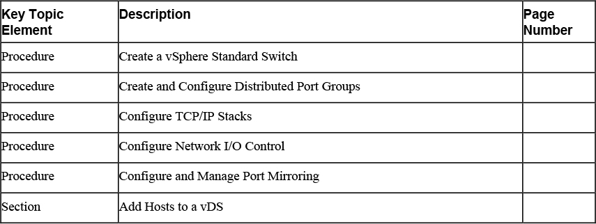
Review All Key Topics
Review the most important topics in this chapter, noted with the Key Topics icon in the outer margin of the page. Table 9-3 lists a reference of these key topics and the page numbers on which each is found.
![]()
Complete Tables and Lists from Memory
Print a copy of Appendix B, “Memory Tables” (found on the companion website), or at least the section for this chapter, and complete the tables and lists from memory. Appendix C, “Memory Tables Answer Key,” also on the companion website includes completed tables and lists to check your work.
Define Key Terms
Define the following key terms from this chapter and check your answers in the glossary.
No new terms are defined in this chapter.
Review Questions
1. You want to use VLAN Guest Tagging with your vSphere Standard Switch. What setting should you make on the standard port group?
a. Set VLAN ID to 0
b. Set VLAN ID to 4095
c. Set VLAN Type to Trunking
d. Set VLAN Type to Guest Tagging
2. You are preparing to upgrade a vDS from version 6.x to 7.0. What step should you take prior to upgrading?
a. Copy the vDS
b. Backup vCenter Server
c. Export the vDS configuration, including the distributed port group configuration.
d. Export the vDS configuration, excluding the distributed port group configuration.
3. You enabled NIOC, reserved virtual machine system traffic, and created a network resource pool. Which one of the following steps do you take to allow a virtual machine to utilize the network resource pool?
a. Edit the virtual machine and set the Network Resources Allocation policy.
b. Add the virtual machine to the resource pool.
c. Assign the network resource pool to the distributed port group where the virtual machines are connected.
d. In the inventory pane, drag and drop the virtual machine onto the network resource pool.
4. You are creating a VMkernel virtual adapter for vMotion traffic. Which of the following is not a valid option?
a. In a standard switch, assign the adapter to the vMotion stack.
b. In a distributed switch, assign the adapter to the vMotion stack.
c. In a standard switch, assign the adapter to the default stack.
d. In a distributed switch, assign the adapter to the Provisioning stack.
5. You want to enable NetFlow in a distributed port group. Which one of the following steps should you take?
a. Change the distributed port group’s monitoring policy.
b. Change the distributed port group’s security policy.
c. In the distributed port group’s Advanced settings, set NetFlow to Enable.
d. Enable Port Mirroring on the distributed port group.