Chapter 2. Storage Infrastructure
This chapter covers the following topics:
• Storage Models and Datastore Types
• Storage Multipathing and Failover
This chapter contains information related to VMware 2V0-21.20 exam objectives 1.3, 1.3.1, 1.3.2, 1.3.3, 1.3.4, 1.3.5, 1.4, 1.6.5, 1.9, 1.9.1, 5.5, 7.4, 7.4.1, 7.4.2, 7.4.3
This chapter provides details for the storage infrastructure, both physical and virtual, involved in a vSphere 7.0 environment.
“Do I Know This Already?” Quiz
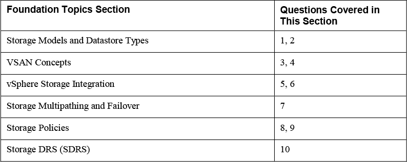
The “Do I Know This Already?” quiz allows you to assess whether you should study this entire chapter or move quickly to the “Exam Preparation Tasks” section. Regardless, the authors recommend that you read the entire chapter at least once. Table 2-1 outlines the major headings in this chapter and the corresponding “Do I Know This Already?” quiz questions. You can find the answers in Appendix A, “Answers to the ‘Do I Know This Already?’ Quizzes and Review Questions.”
Table 2-1 “Do I Know This Already?” Section-to-Question Mapping
1. You need to configure a virtual machine to utilize N-Port ID Virtualization (NPIV). Which of the following are required? (Choose two.)
a. iSCSI
b. vVOLs
c. RDM
d. FCoE
e. vSAN
f. VMFS
2. You are preparing to implement vSphere with Kubernetes. Which type of virtual disk must you provide for storing logs, emptyDir and ConfigMaps?
a. Ephemeral
b. Container image
c. Persistent volume
d. Non-persistent volume.
3. You are planning to implement a vSphere stretched cluster. Which of the following statements is true?
a. You should not enable DRS in automatic mode.
b. You should disable HA datastore heartbeats.
c. If you set PFFT to 0, then you may be able to use SMP-FT
d. If one of the fault domains in inaccessible, then you cannot provision virtual machines.
4. You are planning to implement RAID6 erasure coding for a virtual disk stored in a vSAN datastore. What percentage of the required capacity will be usable?
a. 50%
b. 67%
c. 75%
d. 100%
5. You are preparing want to leverage VAAI in your vSphere environment. Which of the following primitives will not be available for your virtual machines stored in NFS datastores?
a. Atomic Test and Set
b. Full File Clone
c. Extended Statistics
d. Reserve Space
6. You are planning to implement vVOLs. Which of the following are logical I/O proxies?
a. Data-vVol instances
b. Storage Providers
c. Storage Containers
d. Protocol Endpoints
7. You are explaining how vSphere interacts with storage systems. Which of the following steps may occur when VMware NMP receives an I/O request?
a. The PSP issues the I/O request on the appropriate physical path.
b. The SATP issues the I/O request on the appropriate physical path.
c. The PSP activates the inactive path
d. The PSP calls the appropriate SATP
8. In your vSphere environment where VASA is not implemented, you are planning to leverage storage policies associated with devices in your storage array. Which type of storage policies should you create?
a. VM Storage Policy for Host-Based Data Services
b. VM Storage Policy for vVols
c. VM Storage Policy for Tag-Based Placement
d. vSAN Storage Policy
9. You are configuring storage policies for use with your vSAN cluster. Which of the following is not an available option?
a. Number of replicas per object
b. Number of disk stripes per object
c. Primary level of failures to tolerate
d. Secondary level of failures to tolerate
10. You are testing Storage DRS involving a datastore where the utilized space on one datastore is 82% and 79% on another datastore. You observe that SDRS does not make a migration recommendation. What may be the reason?
a. The Space Utilization Difference threshold is set too low.
b. The Space Utilization Difference threshold is set too high.
c. The Space Utilization Difference threshold is set to 78%
d. The Space Utilization Difference threshold is set to 80%
Foundation Topics
Storage Models and Datastore Types
This section describes the storage models and datastore types available in vSphere and how virtual machines access storage.
How Virtual Machines Access Storage
A virtual machine communicates with its virtual disk stored on a datastore by issuing SCSI commands. The SCSI commands are encapsulated into other forms, depending on the protocol that the ESXi host uses to connect to a storage device on which the datastore resides, as illustrated in Figure 2-1.
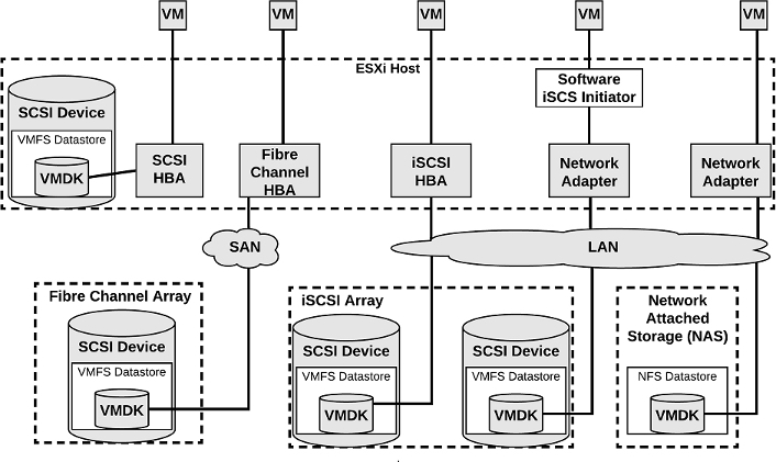
Figure 2-1 Virtual Machine Storage
Storage Virtualization – Traditional Model
Storage virtualization refers to a logical abstraction of physical storage resources and capacities from virtual machines. ESXi provides host-level storage virtualization. In vSphere environments, a traditional model is built around the following storage technologies and ESXi virtualization features.
Storage Device or LUN
In common ESXi vocabulary, the terms device and LUN are used interchangeably. The terms represent storage volumes that are presented to the host from a block storage system and is available to ESXi for formatting.
Virtual Disk
Virtual disks are sets of files that reside on a datastore that is deployed on physical storage. From the standpoint of the virtual machine, each virtual disk appears as if it were a SCSI drive connected to a SCSI controller. The physical storage is transparent to the virtual machine guest operating system and applications.
Local Storage
Local storage can be internal hard disks located inside your ESXi host and external storage systems connected to the host directly through protocols such as SAS or SATA. Local storage does not require a storage network to communicate with your host.
Fibre Channel
Fibre Channel (FC) is a storage protocol that a storage area network (SAN) uses to transfer data traffic from ESXi host servers to shared storage. It packages SCSI commands into FC frames. The ESXi host uses Fibre Channel host bus adapters (HBAs) to connect to the FC SAN, as illustrated in Figure 2-1. Unless you use direct-connected Fibre Channel storage, you need Fibre Channel switches to route storage traffic. If your host contains FCoE (Fibre Channel over Ethernet) adapters, you can connect to your shared Fibre Channel devices by using an Ethernet network.
iSCSI
Internet SCSI (iSCSI) is a SAN transport that can use Ethernet connections between ESXi hosts and storage systems. To connect to the storage systems, your hosts use hardware iSCSI adapters or software iSCSI initiators with standard network adapters.
With hardware iSCSI HBAs, the host connects to the storage through a hardware adapter that offloads the iSCSI and network processing. Hardware iSCSI adapters can be dependent and independent. With software iSCSI adapters, the host uses a software-based iSCSI initiator in the VMkernel and a standard network adapter to connect to storage. Both the iSCSI HBA and the Software iSCSi Initiator are illustrated in Figure 2-1.
FCoE
If an ESXi host contains FCoE (Fibre Channel over Ethernet) adapters, it can connect to shared Fibre Channel devices by using an Ethernet network.
NAS / NFS
Using NFS, vSphere stores your virtual machines files on remote file servers accessed over a standard TCP/IP network. ESXi 7.0 uses Network File System (NFS) protocol version 3 and 4.1 to communicate with the NAS/NFS servers, as illustrated in Figure 2-1. You can use NFS datastores to store and manage virtual machines in the same way that you use the VMFS datastores.
VMFS
The datastores that you deploy on block storage devices use the native vSphere Virtual Machine File System (VMFS) format. It is a special high-performance file system format that is optimized for storing virtual machines.
Raw Device Mappings (RDMs)
![]()
An RDM is a mapping file containing metadata that resides in a VMFS datastore and acts as a proxy for a physical storage device (LUN), allowing a virtual machine to access the storage device directly. It gives you some of the advantages of direct access to a physical device and keeps some of the management advantages of VMFS based virtual disks. The components involved with an RDM are illustrated in Figure 2-2.

Figure 2-2 RDM Diagram
You can envision an RDM as a symbolic link from a VMFS volume to the storage device. The mapping makes the storage device appear as a file in a VMFS volume. The virtual machine configuration references the RDM, not the storage device. RDMs support two compatibility modes.
• Virtual compatibility mode: The RDM acts much like a virtual disk file, enabling extra virtual disk features, such as the use of virtual machine snapshot and the use of disk modes (dependent, independent – persistent, independent – nonpersistent).
• Physical compatibility mode, The RDM offers direct access to the SCSI device supporting applications that require lower-level control.
Virtual disk files are preferred over RDMs for manageability You should only use RDMs when necessary. Use Cases for RDMs include the following.
• You plan to install software in the virtual machine that requires features inherent to the SAN, such as SAN management, storage base snapshots, or storage-based replication. The RDM enables the virtual machine to have the required access to the storage device.
• You plan to configure MSCS clustering in a manner that spans physical hosts, such as virtual-to-virtual clusters and physical-to-virtual clusters. You should configure the data and quorum disks as RDMs rather than virtual disk files.
Benefits of RDMs include the following.
• User-Friendly Persistent Names: Much like naming a VMFS datastore, you can provide a friendly name to a mapped device, rather than using its device name.
• Dynamic Name Resolution: If physical changes (such as adapter hardware changes, path changes, or device relocation) occur, the RDM is updated automatically. The virtual machines do not need to be updated, because they reference the RDM,
• Distributed File Locking: VMFS distributed locking is used to make it safe for two virtual machines on different servers to access the same LUN.
• File Permissions: Permissions are set on the mapping file to effectively apply permissions to the mapped file, much like they are applied to virtual disks.
• File System Operations: Most file system operations that are valid for an ordinary file can be applied to the mapping file and redirected to the mapped device.
• Snapshots: Virtual machine snapshots can be applied to the mapped volume, but not when the RDM is used in physical compatibility mode.
• vMotion: You can migrate the virtual machine with vMotion, as vCenter Server uses the RDM as a proxy, which enables the use of the same migration mechanism used for virtual disk files.
• SAN Management Agents: Enables the use of SAN management agents (SCSI target-based software) inside a virtual machine, which require hardware-specific SCSI commands. This requires physical compatibility mode for the RDM.
• N-Port ID Virtualization (NPIV): You can use NPIV technology that allows a single Fibre Channel HBA port to register with the fabric using multiple worldwide port names (WWPNs). This ability makes the HBA port appear as multiple virtual ports, each having its own ID and virtual port name. Virtual machines can then claim each of these virtual ports and use them for all RDM traffic. NPIV requires the use of virtual machines with RDMs.
Note
To support vMotion involving RDMs, be sure to maintain consistent LUN IDs for RDMs across all participating ESXi hosts.
Note
To support vMotion for NPIV enabled virtual machines, place the RDM files, virtual machine configuration file, and other virtual machines in the same datastore. You cannot perform Storage vMotion when NPIV is enabled.
Software Defined Storage Models
In addition to abstracting underlying storage capacities from VMs, as traditional storage models do, software-defined storage abstracts storage capabilities. With the software-defined storage model, a virtual machine becomes a unit of storage provisioning and can be managed through a flexible policy-based mechanism. The model involves the following vSphere technologies
VSAN
vSAN is a layer of distributed software that runs natively on each hypervisor in the cluster. It aggregates local or direct-attached capacity creates a single storage pool shared across all hosts in the vSAN cluster.
vVOLs
Virtual volumes are encapsulations of virtual machine files, virtual disks, and their derivatives that are stored natively inside a storage system. You do not provision Virtual volumes directly. Instead, they are automatically created when you create, clone, or snapshot a virtual machine. Each virtual machine can be associated to one or more virtual volumes.
The Virtual Volumes (vVols) functionality changes the storage management paradigm from managing space inside datastores to managing abstract storage objects handled by storage arrays. With Virtual Volumes, each virtual machine (rather than a datastore) is a unit of storage management. You can apply storage polices per virtual machine, rather than per LUN or datastore.
Storage Policy Based Management
Storage Policy Based Management (SPBM) is a framework that provides a single control panel across various data services and storage solutions, including vSAN and Virtual Volumes. Using storage policies, the framework aligns application demands of your virtual machines with capabilities provided by storage entities.
I/O Filters
I/O filters are software components that can be installed on ESXi hosts and can offer additional data services to virtual machines. Depending on implementation, the services might include replication, encryption, caching, and so on.
Datastore Types
In vSphere 7.0, you can use the following datastore types.
VMFS
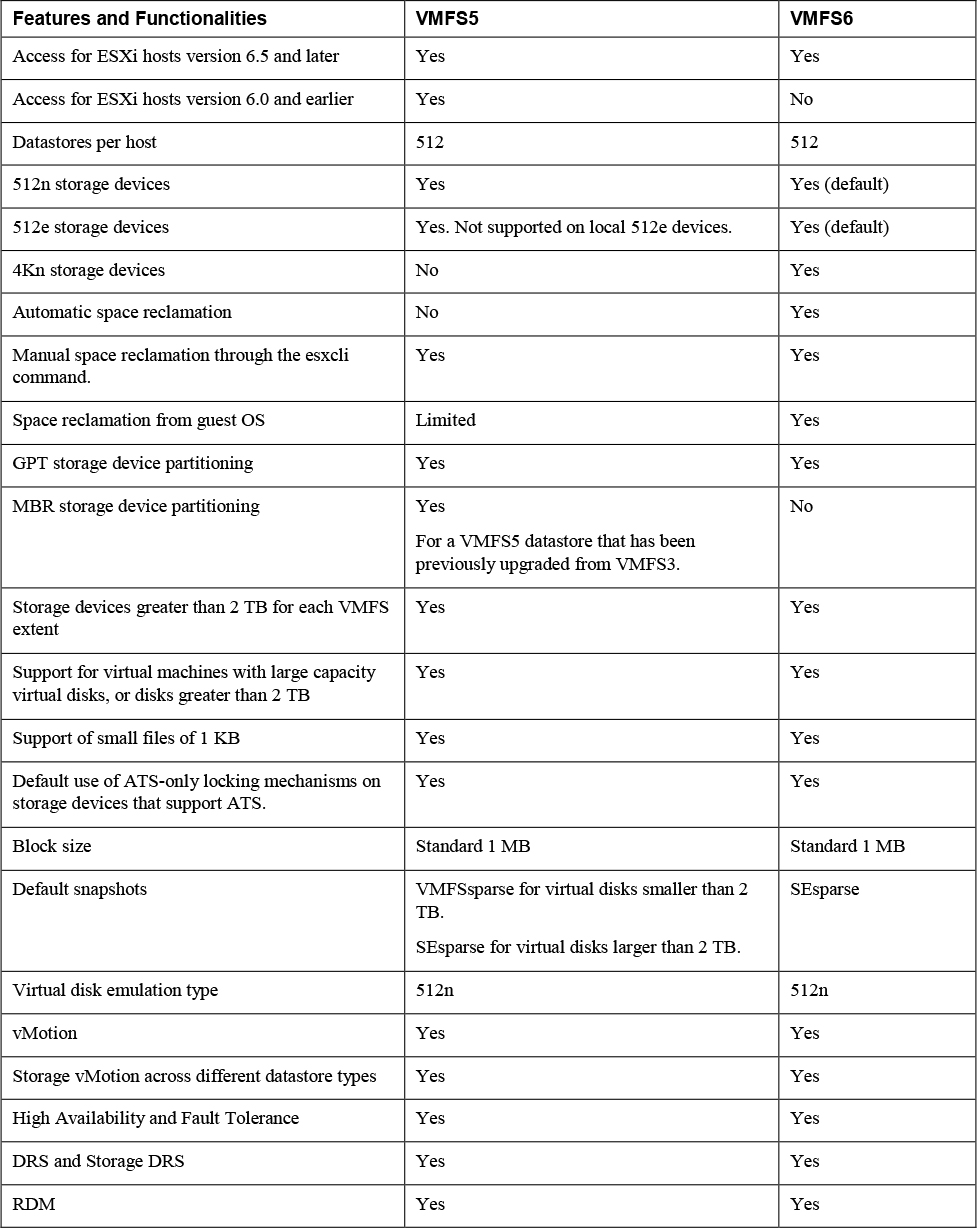
You can create VMFS datastores on fiber channel, iSCSI, FCoE, and local storage devices. ESXi 7.0 supports VMFS versions 5 and 6 for read and write. ESXi 7.0 does not support VMFS version 3. Table 2-2 compares the features and functionalities of VMFS versions 5 and 6.
Table 2-2 Comparing VMFS Versions 5 and 6
When working with VMFS datastores in vSphere 7.0, consider the following.
• Datastore Extents. A spanned VMFS datastore must use only homogeneous storage devices, either 512n, 512e, or 4Kn. The spanned datastore cannot extend over devices of different formats.
• Block Size. The block size on a VMFS datastore defines the maximum file size and the amount of space a file occupies. VMFS5 and VMFS6 datastores support the block size of 1 MB.
• Storage vMotion. Storage vMotion supports migration across VMFS, vSAN, and Virtual Volumes datastores. vCenter Server performs compatibility checks to validate Storage vMotion across different types of datastores.
• Storage DRS. VMFS5 and VMFS6 can coexist in the same datastore cluster. However, all datastores in the cluster must use homogeneous storage devices. Do not mix devices of different formats within the same datastore cluster.
• Device Partition Formats. Any new VMFS5 or VMFS6 datastore uses GUID partition table (GPT) to format the storage device. The GPT format enables you to create datastores larger than 2 TB. If your VMFS5 datastore has been previously upgraded from VMFS3, it continues to use the master boot record (MBR) partition format, which is characteristic for VMFS3. Conversion to GPT happens only after you expand the datastore to a size larger than 2 TB
NFS
You can create NFS datastores on NAS storage. ESXi 7.0supports NFS protocols version 3 and 4.1. To support both versions, ESXi 7.0 uses two different NFS clients. Table 2-3 compares the capabilities of NFS versions 3 and 4.1.
Table 2-3 NFS Versions 3 and 4.1 Characteristics

Table 2-4 compares vSphere 7.0 features and related solutions supported by NFS versions 3 and 4.1.
Table 2-4 NFS Versions 3 and 4.1 Support for vSphere Features and Solutions

When you upgrade ESXi from a version earlier than 6.5, existing NFS 4.1 datastores automatically begin supporting functionalities that were not available in the previous ESXi release, such as Virtual Volumes and hardware acceleration. ESXi does not support automatic datastore conversions from NFS version 3 to NFS 4.1. You can use Storage vMotion to migrate virtual machines from NFS3 datastores to NFS4.1 datastores. In some cases, a storage vendor may provide a conversion method from NFS 3 to NFS 4.1. In some cases, you may be able to unmount the NFS 3 datastore from all hosts and remount it as NFS 4.1. The datastore can never be mounted by using both protocols at the same time.
vVOLs Datastore
You can create a vVols datastore in an environment with a compliant storage system. A virtual volume, which is created and manipulated out of band by a vSphere APIs for Storage Awareness (VASA) provider, represents a storage container in vSphere. The VASA provider maps virtual disk objects and their derivatives, such as clones, snapshots, and replicas, directly to the virtual volumes on the storage system. ESXi hosts access virtual volumes through an intermediate point in the data path, called the protocol endpoint. The protocol endpoints serve as a gateway for I/O between ESXi hosts and the storage system, using Fibre Channel, FCoE, iSCSI, or NFS.
vSAN Datastore
You can create a vSAN datastore in a vSAN cluster. vSAN is a hyperconverged storage solution, which combines storage, compute, and virtualization into a single physical server or cluster. The following section describes the concepts, benefits, and terminology associated with vSAN.
Storage in vSphere with Kubernetes
To support the different types of storage objects in Kubernetes, vSphere with Kubernetes provides three types of virtual disks, which are ephemeral, container image, and persistent volume.
A vSphere Pod requires ephemeral storage to store Kubernetes objects, such as logs, emptyDir volumes, and ConfigMaps.. The ephemeral, or transient, storage exists if the vSphere Pod exists.
The vSphere Pod mounts images used by its containers as image virtual disks, enabling the container to use the software contained in the images. When the vSphere Pod life cycle completes, the image virtual disks are detached from the vSphere Pod. You can specify a datastore to use as the container image cache, such that subsequent pods can pull it from the cache rather than the external container registry.
Some Kubernetes workloads require persistent storage to store the data independent of the pod. Persistent volume objects in vSphere with Kubernetes are backed by the First Class Disks on a datastore. A First Class Disk (FCD), which is also called a an Improved Virtual Disk, is a named virtual disk that is not associated with a VM. To provide the persistent storage, you can use the Workload Management feature in the vSphere Client to associate one or more storage policies with the appropriate namespace.
VMware NVMe
NVMe storage is a low latency, low CPU usage, and high performance alternative to SCSI storage. It is designed for use with faster storage media equipped with non-volatile memory, such as flash devices. NVMe storage can be directly attached to a host using a PCIe interface or indirectly through different fabric transport (NVMe-oF).
In a NVMe storage array, a namespace represents a storage volume. A NVMe namespace is analogous to a storage device (LUN) in other storage arrays. In the vSphere Client, NVMe namespace appear in the list of storage devices. You can use the device to create a VMFS datastore.
Requirements for NVMe over PCIe
NVMe over PCIe requires the following.
• Local NVMe storage devices.
• Compatible ESXi host.
• Hardware NVMe over PCIe adapter.
Requirements for NVMe over RDMA (RoCE v2)
NVMe over PCIe requires the following.
• NVMe storage array with NVMe over RDMA (RoCE v2) transport support
• Compatible ESXi host.
• Ethernet switches supporting a lossless network.
• Network adapter that supports RDMA over Converged Ethernet (RoCE v2).
• Software NVMe over RDMA adapter.
• NVMe controller.
Requirements for NVMe over Fibre Channel
NVMe over PCIe requires the following.
• Fibre Channel storage array that supports NVMe.
• Compatible ESXi host.
• Hardware NVMe adapter. (A Fibre Channel HBA that supports NVMe)
• NVMe controller.
VMware High Performance Plug-in (HPP)
VMware provides the High-Performance Plug-in (HPP) to improve the performance of NVMe devices on your ESXi host. HPP replaces NMP for high-speed devices, such as NVMe.
HPP is the default plug-in that claims NVMe-oF targets. Within ESXi, the NVMe-oF targets are emulated and presented to users as SCSI targets. The HPP supports only active/active and implicit ALUA targets.
NMP is the default plug-in for local NVMe devices, but you can replace it with HPP. NMP cannot be used to claim the NVMe-oF targets. High-Performance Plug-in (HPP) should be used for NVMe-oF.
Table 2-5 describes the vSphere 7.0 Support for HPP
Table 2-5 vSphere 7.0 HPP Support
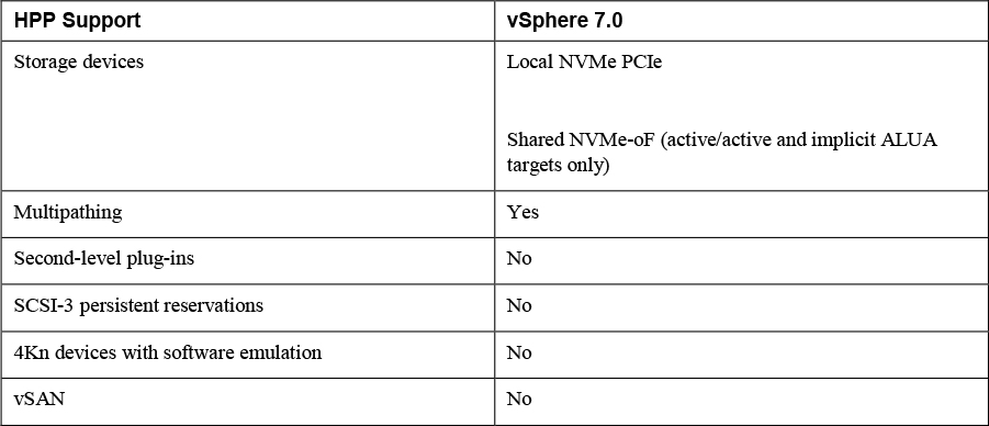
Table 2-6 describes the Path Selection Schemes (PSS) used by HPP when selecting physical paths for I/O requests.
Table 2-6 HPP Path Selection Schemes (PSS)

HPP best practices include the following.
• Use a vSphere version that supports HPP.
• Use HPP for NVMe local and networked devices.
• Do not use HPP with HDDs or any flash devices that cannot sustain 200,000 IOPS.
• If you use NVMe with Fibre Channel devices, follow your vendor recommendations.
• If you use NVMe-oF, do not mix transport types to access the same namespace.
• When using NVMe-oF namespaces, make sure that active paths are presented to the host.
• Configure VMs to use VMware Paravirtual controllers.
• Set the latency sensitive threshold for virtual machines.
• If a single VM drives a significant share of the device's I/O workload, consider spreading the I/O across multiple virtual disks, attached to separate virtual controllers in the VM (or you risk that the I/O may saturate a CPU core).
vSAN Concepts
vSAN virtualizes the local, physical storage resources of ESXi hosts by turning them into pools of storage that can be used by virtual machines based on their quality-of-service requirements. You can configure vSAN as a hybrid or an all-flash cluster. Hybrid clusters use flash devices for the cache layer and magnetic disks for the storage capacity layer. All Flash clusters use flash devices for both cache and capacity.
You can enable vSAN on existing host clusters as well as new clusters. You can expand the datastore by adding hosts with capacity devices to the cluster or by adding local dives to the existing hosts in the cluster. vSAN works best when all ESXi hosts in the cluster are configured similarly, including similar or identical storage configurations. A consistent configuration enables vSAN to balance virtual machine storage components across all devices and hosts in the cluster. Hosts without any local devices also can participate and run their virtual machines on the vSAN datastore.
If a host contributes some of its local storage to a VSAN cluster, then it must contribute at least one device for cache. The drives contributed by a host form one or more disk groups. Each disk group contains a flash cache device and at least one capacity devices. Each host can be configured to use multiple disk groups.
vSAN offers many features of a traditional SAN. Its main limitations are that each vSAN instance can only support one cluster. It has the following benefits over traditional storage.
• vSAN does not require dedicated, storage network, such as on a Fibre Channel (FC) or Storage Area Network (SAN).
• With vSAN, you do not have to pre-allocate and pre-configure storage volumes (LUNs).
• vSAN does not behave like traditional storage volumes based on LUNs or NFS shares. You do not have to apply standard storage protocols, such as FC, and you do not need to format the storage directly.
• You can deploy, manage, and monitor vSAN by using the vSphere Client, rather than other storage management tools.
• A vSphere administrator, rather than storage administrator, can manage a vSAN environment.
• When deploying virtual machines, you can use automatically assigned storage policies with vSAN.
vSAN Characteristics
vSAN is like a network distributed RAID for local disks, transforming them into shared storage. vSAN uses of copies of VM data, where one copy is local and another copy is on one of the other nodes in the cluster. The number of copies is configurable. Here are some of the features of vSAN:
• Shared storage support: The VMware features which require shared storage (HA, vMotion, DRS) are available with vSAN.
• On-disk format: highly scalable snapshot and clone management on a vSAN cluster.
• All-flash and hybrid configurations: vSAN can be used on hosts with all-flash storage, or with hybrid storage (combination SSD and traditional HDDs)
• Fault domains: Fault domains can be configured to protect against rack or chassis failures, preventing all copies of VM disk data from residing on the same rack or chassis.
• iSCSI target service: This allows the vSAN datastore to be visible and usable by ESXi hosts outside of the cluster and by physical bare-metal systems.
• Stretched cluster: vSAN supports stretching a cluster across physical geographic locations.
• Support for Windows Failover Clusters (WSFC): SCSI-3 Persistent Reservations (SCSI3-PR) are supported on virtual disks, which are required for shared disks and WSFC. MS SQL 2012 or later is supported on vSAN. The following limitations apply:
• Maximum of 6 application nodes in each vSAN cluster.
• Maximum of 64 shared disks per ESXi host.
• vSAN health service: This includes health checks for monitoring and troubleshooting purposes.
• VSAN performance service: This service includes statistics for monitoring vSAN performance metrics. This can be monitored at the cluster level, ESXi host, disk group, disk, or VMs.
• Integration with vSphere storage features: Snapshots, linked clones, and vSphere Replication are all supported on vSAN datastores.
• Virtual Machine Storage Policies: Policies can be defined for VMs on vSAN. If no policies are defined, a default vSAN policy is applied.
• Rapid provisioning: This provides fast storage provisioning for VM creation and deployment from templates.
• Deduplication and compression: Block-level deduplication and compression are available space-saving mechanisms on vSAN, which can be configured at the cluster level, and applied to each disk group.
• Data at rest encryption: Data at rest encryption is data that is not in transit, and no processes are being done, for example, deduplication or compression. If drives are removed, the data on those drives is encrypted.
• SDK support: This is an extension (written in Java) of the VMware vSphere Management SDK. It has libraries, code examples, and documentation for assistance in automating and troubleshooting vSAN deployments.
vSAN Terminology
• Disk Group: a group of local disks on an ESXi host contributing to the vSAN datastore. This must include one cache device and one capacity device. In a hybrid cluster, a flash disk is the cache device, and magnetic disks are used for capacity devices. In all-flash clusters, flash storage is used for both cache and capacity.
• Consumed Capacity: the amount of physical space used up by virtual machines at any point in time.
• Object-Based Storage: data is stored in vSAN by way of objects, which are flexible data containers. Objects are logical volumes withy data and metadata spread among nodes in the cluster. Virtual disks are objects, as are snapshots. For object creation and placement, vSAN takes the following into account:
• Virtual disk policy and requirements are verified
• The number of copies (replicas) is verified; the amount of flash read cache allocated for replicas, number of stripes for replica as well as location is determined.
• Policy compliance of virtual disks.
• Mirrors and witnesses placed on different hosts or fault domains.
• vSAN Datastore: Like other datastores, a vSAN datastore which will appear in the Storage Inventory view in vSphere. vSAN clusters provide a single datastore to be available for every host in the cluster, even if they do not contribute storage to vSAN. An ESX hosts can mount VMFS and NFS datastores in addition to the vSAN datastore. Storage vMotion can be utilized to migrate VMs between any datastore type.
• Objects and Components:
• VM Home Namespace: The VM home directory where all of the VM files are stored.
• VMDK: virtual disks for VMs.
• VM Swap Object: allows memory to be swapped to disk during periods of contention. This is created at VM power on.
• Snapshot Delta VMDKs: these are change files created when a snapshot is taken of a VM.
• Memory object: This is created when a VM is snapshotted (and choosing to retain the VM’s memory) or suspended.
• Virtual Machine Compliance Status: Can be Compliant and Noncompliant, depending on whether each of the virtual machine’s objects meet the requirements of the assigned storage policy. The status is available on the Virtual Disks Page on the Physical Disk Placement tab.
• Component State: Degraded and Absent States:
• Degraded: vSAN detects a permanent failure of a component.
• Absent: vSAN detects a temporary component failure.
• Object State: Healthy and Unhealthy:
• Healthy: At least one RAID 1 mirror is available, or enough segments are available for RAID 5 or 6.
• Unhealthy: no full mirror is available, or not enough segments are available for RAID 5 or 6.
• Witness: A component only consisting of metadata. It is used as a tiebreaker. Witnesses consume about 2 MB of space for metadata on a vSAN datastore when on-disk format 1.0 is used, and 4 MB when on-disk format 2.0 or later is used.
• Storage Policy-Based Management (SPBM): VM storage requirements are defined as a policy and vSAN ensures these policies are met when placing objects. If you don’t apply a storage policy when creating or deploying VMs, the default vSAN policy with Primary level of failures to tolerate is set to 1 with a single stripe per object, and thin provisioned disk.
• Ruby vSphere Console (RVC): This is a command-line interface used for managing and troubleshooting vSAN. RVC provides a cluster-wide view and is included with the vCenter Server deployment.
• VMware PowerCLI: vSAN cmdlets are included with PowerCLI to allow administration of vSAN.
• vSAN Observer: this is a web-based utility, built on top of RVC, used for performance analysis and monitoring. This can display performance statistics on the capacity tier, disk group statistics, CPU load, memory consumption, and vSAN objects in-memory and their distribution across the cluster.
• vSAN Ready Node: This is a preconfigured deployment which is provided by VMware partners. This is a validated design using certified hardware.
• User-Defined vSAN Cluster: This is a vSAN deployment making use of hardware selected by you.
Note
The capacity disks contribute to the advertised datastore capacity. The flash cache devices are not included as capacity
What is New in VSAN 7.0
The following new features are available in vSAN 7.0
• vSphere Lifecycle Manager. vSphere Lifecycle Manager uses a desired-state model to enable simple, consistent lifecycle management for your ESXi hosts, including drivers and firmware.
• Integrated File Services. The vSAN native File Service enables you to create and present NFS v4.1 and v3 file shares, effectively extending vSAN capabilities to files, such as availability, security, storage efficiency, and operations management.
• Native support for NVMe hot plug. The plug-in provides a consistent way of servicing NVMe devices and provides operational efficiency.
• I/O redirect based on capacity imbalance with stretched clusters. This feature improves uptime of your VMs by redirecting all virtual machine I/O from a capacity-strained site to the other site.
• Skyline integration with vSphere health and vSAN health. Skyline Health for vSphere and vSAN are available, enabling a native, in-product health monitoring and consistent, proactive analysis.
• Remove EZT for shared disk. vSAN 7.0 eliminates the prerequisite that shared virtual disks using the multi-writer flag must also use the eager zero thick format.
• Support vSAN memory as metric in performance service. vSAN memory usage is now available in the Performance Charts (vSphere Client) and through the API.
• Visibility of vSphere Replication objects. vSphere replication objects are visible in vSAN capacity view.
• Support for large capacity drives. Support for 32TB physical capacity drives and up to 1PB logical capacity when deduplication and compression is enabled.
• Immediate repair after new witness is deployed. vSAN immediately invokes a repair object operation after a witness has been added during a replace witness operation.
• vSphere with Kubernetes integration. CNS is the default storage platform for vSphere with Kubernetes. This integration enables various stateful containerized workloads to be deployed on vSphere with Kubernetes Supervisor and Guest clusters on vSAN, VMFS and NFS datastores.
• File-based persistent volumes. Kubernetes developers can dynamically create shared (Read/Write/Many) persistent volumes for applications. Multiple pods can share data. vSAN native File Services is the foundation that enables this capability.
• vVol support for modern applications. You can deploy modern Kubernetes applications to external storage arrays on vSphere using the CNS support added for vVols. vSphere now enables unified management for Persistent Volumes across vSAN, NFS, VMFS and vVols.
• vSAN VCG notification service. You can get notified through email about any changes to vSAN HCL components such as vSAN ReadyNode, I/O controller, drives (NVMe, SSD, HDD) and get notified through email about any changes.
Note
In vCenter Server 7.0.0a, vSAN File Services and vSphere Lifecycle Manager can be enabled simultaneously on the same vSAN cluster.
VSAN Deployment Options
Standard Cluster
A standard vSAN cluster, which is illustrated in Figure 2-3, consists of a minimum of three hosts, typically residing at the same location, and connected on the same Layer 2 network. 10 Gb network connections are required for all-flash clusters and are recommended for hybrid configurations.
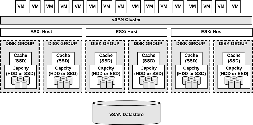
Figure 2-3 A Standard vSAN cluster
2 Host vSAN Cluster
The main use case for a two host vSAN cluster is a remote office/branch office environment, where workloads require high availability. A two host vSAN cluster, which is illustrated in Figure 2-4, consists of two hosts at the same location, connected to the same network switch or directly connected. You can configure a two host vSAN cluster that uses a third host as a witness, which can be located separately from the remote office. Usually the witness resides at the main site, along with the vCenter Server. For more details on the Witness host, see the next section on Stretched Clusters.
![]()

Figure 2-4 A Two-Node vSAN cluster
Stretched Cluster
![]()
You can create a stretched vSAN cluster that spans two geographic sites and continues to function if a failure or scheduled maintenance occurs at one site. Stretched clusters, which are typically deployed in metropolitan or campus environments with short distances between sites, provide a higher level of availability and inter-site load balancing.
You can use stretched clusters for planned maintenance and disaster avoidance scenarios, where both data sites are active. If either site fails, vSAN uses the storage on the other site and vSphere HA can restart virtual machines on the remaining active site.
You should designate one site as the preferred site, which becomes the only used site in the event of a network connectivity loss between the two sites. A vSAN stretched cluster can tolerate one link failure at a time without data becoming unavailable. During a site failure or loss of network connection, vSAN automatically switches to fully functional sites.
Note
A link failure is a loss of network connection between the two sites or between one site and the witness host.
Each stretched cluster consists of two data sites and one witness host. The witness host resides at a third site and contains the witness components of virtual machine objects. It contains only metadata and does not participate in storage operations. Figure 2-5 shows an example of a stretched cluster, where the witness nodes resides at a third site along with vCenter Server.
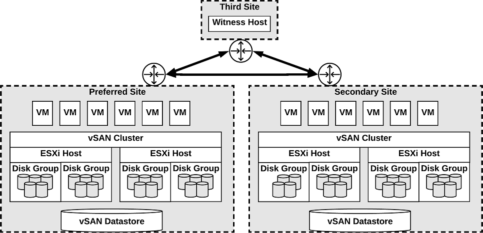
Figure 2-5 A Stretched vSAN cluster
The witness host acts as a tiebreaker for decisions regarding availability of datastore components. The witness host typically forms a vSAN cluster with the preferred site, but forms a cluster with secondary site, if the preferred site becomes isolated. When the preferred site is online again, data is resynchronized.
Characteristics of the witness host.
• It can use low bandwidth/high latency links.
• It cannot run VMs.
• It can support only one vSAN stretched cluster.
• It requires a VMkernel adapter enabled for vSAN traffic with connections to all hosts in the cluster. It can have only one VMkernel adapter dedicated to vSAN but can have another for management.
• It must be a standalone host. It cannot be added to any other cluster or moved in inventory through vCenter Server.
• It can be a physical ESXi host or a VM-based ESXi host.
Note
The witness virtual appliance is an ESXi host in a VM, packaged as an OVF or OVA, which is available in different options, based on the size of the deployment.
Each site in a stretched cluster resides in a separate fault domain. Three default domains are used: the preferred site, the secondary site, and a witness host.
Beginning with vSAN 6,6, you can provide an extra level of local fault protection for objects in stretched clusters using the following policy rules.
• Primary level of failures to tolerate (PFTT) defines the number of site failures that a virtual machine object can tolerate. For a stretched cluster, only a value of 0 or 1 is supported.
• Secondary level of failures to tolerate (SFTT) defines the number of additional host failures that the object can tolerate after the number of site failures (PFTT) is reached. For example, If PFTT = 1 and SFTT = 2, and one site is unavailable, then the cluster can tolerate two additional host failures. The default value is 0, and the maximum value is 3.
• Data Locality enables you to restrict virtual machine objects to a selected site in the stretched cluster. The default value is None, but you can change it to Preferred or Secondary. Data Locality is available only if PFTT = 0.
Note
If you set SFTT for a stretched cluster, the Fault tolerance method rule applies to the SFTT. The failure tolerance method used for the PFTT is set to RAID 1.
Consider the following guidelines and best practices for stretched clusters:
• DRS must be enabled on the cluster.
• Create two host groups, two virtual machines groups, and two VM-Host affinity rules to effectively control the placement of virtual machines between the preferred and the secondary sites.
• HA must be enabled on the cluster in a manner such that it respects the VM-Host affinity rules.
• Disable HA datastore heartbeats.
• On disk format 2.0 or later is required.
• Set Failures to tolerate to 1
• Symmetric Multiprocessing Fault Tolerance (SMP-FT) is supported when PFFT is set to 0 and Data Locality is set to Preferred or Secondary. SMP-FT is not supported if PFFT is set to 1.
• Using esxcli to add or remove hosts is not supported.
• If one of the three fault domains (preferred site, secondary site, or witness host) is inaccessible, new VMs can still be provisioned, but are non-compliant until the partitioned site rejoins the cluster. This implicit force provisioning is performed only when two of the three fault domains are available.
• If an entire site goes offline due to loss of power or network connection, restart the site immediately. Bring all hosts online approximately at the same time to avoid resynchronizing a large amount of data across the sites.
• If a host is permanently unavailable, remove the host from the cluster before performing any reconfiguration tasks.
• To deploy witnesses for multiple clusters, do not clone a virtual machine that is already configured as a witness. Instead, you can first deploy a VM from OVF, then clone the VM, and configure each clone as a witness host for a different cluster
The stretched cluster network must meet the following requirements.
• The management network requires connectivity across all three sites, using a Layer 2 stretched network or a Layer 3 network.
• The vSAN network requires connectivity across all three sites using a Layer 2 stretched network between the two data sites and a Layer 3 network between the data sites and the witness host..
• The virtual machine network requires connectivity between the data sites, but not the witness host. Use a Layer 2 stretched network or Layer 3 network between the data sites. Virtual machines do not require a new IP address following failover to the other site.
• The vMotion network requires connectivity between the data sites, but not the witness host. Use a Layer 2 stretched or a Layer 3 network between data sites.
VSAN Limitations
![]()
Limitations of vSAN include the following.
• No support for hosts participating in multiple vSAN clusters.
• No support for vSphere DPM and Storage I/O Control.
• No support for SE Sparse disks.
• No support for RDM, VMFS, diagnostic partition, and other device access features.
vSAN Space Efficiency
You can use space efficiency techniques in vSAN to reduce the amount of space for storing data. These include the use of any or all of the following:
• Thin provisioning: only consuming the space on disk that is used (and not the total allocated virtual disk space).
• Deduplication: reduction of duplicated data blocks by using SHA-1 hashes for data blocks.
• Compression: compressing data using LZ4, which is a lightweight compression mechanism.
• Erasure Coding: creating a strip of data blocks with a parity block. This is similar to parity with RAID configurations, except it spans ESXi hosts in the cluster, instead of disks in the host.
SCSI Unmap
SCSI UNMAP commands, which are supported in vSAN 6.7 Update 1 and later, enable you to reclaim storage space that is mapped to deleted vSAN objects. vSAN supports the SCSI UNMAP commands issued within a guest operating system to reclaim storage space. vSAN supports offline unmaps as well as inline unmaps. On Linux OS, offline unmaps are performed with the fstrim(8) command, and inline unmaps are performed when the mount -o discard command is used. On Windows OS, NTFS performs inline unmaps by default.
Deduplication and Compression
All-flash vSAN clusters support deduplication and compression. Deduplication removes redundant data blocks. Compression removes additional redundant data within each data block. Together, these techniques reduce the amount of space required to store data. As vSAN moves data from the cache tier to the capacity tier, it applies deduplication and then applies compression.
You can enable deduplication and compression as a cluster-wide setting, but they are applied on a disk group basis, where redundant data is reduced within each disk group.
When you enable or disable deduplication and compression, vSAN performs a rolling reformat of every disk group on every host, which may take a long time. You should first verify that enough physical capacity is available to place your data. You should minimize how frequently these operations are performed.
Note
Deduplication and compression might not be effective for encrypted VMs.
The amount of storage reduction achieved by deduplication and compression depends on many factors, such as the type of data stored and the number of duplicate blocks. Larger disk groups tend to provide a higher deduplication ratio.
RAID 5 and RAID 6 Erasure Coding
In a vSAN cluster, you can use RAID 5 or RAID 6 erasure coding to protect against data loss while increasing storage efficiency when compared with RAID 1 (mirroring). You can configure RAID 5 on all-flash clusters with four or more fault domains. You can configure RAID 5 or RAID 6 on all-flash clusters with six or more fault domains.
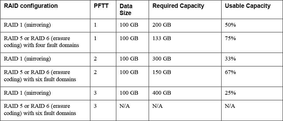
RAID 5 or RAID 6 erasure coding requires less storage space to protect your data than RAID 1 mirroring. For example, if you protect a VM by setting the Primary level of failures to tolerate (PFTT) to 1, RAID 1 requires twice the virtual disk size and RAID 5 requires 1.33 times the virtual disk size. You can use Table 2-7 to compare RAID 1 with RAID 5/6 for a 100 GB virtual disk.
Table 2-7 RAID Configuration Comparison
Before configuring RAID 5 or RAID 6 erasure coding in a vSAN cluster, you should consider the following.
• All-flash disk groups are required.
• On-disk format version 3.0 or later is required.
• A valid license supporting RAID 5/6 is required.
• You can enable deduplication and compression on the vSAN cluster to achieve additional space savings.
• PFTT must be set to less than 3.
vSAN Encryption
You can use data at rest encryption in a vSAN cluster, where all data is encrypted after all other processing, such as deduplication, is performed All files are encrypted, so all virtual machines and their data are protected. Only administrators with encryption privileges can perform encryption and decryption tasks. Data at rest encryption protects data on storage devices in case a device is removed from the cluster.
vSAN encryption requires an external Key Management Server (KMS), the vCenter Server system, and your ESXi hosts. vCenter Server requests encryption keys from an external KMS. The KMS generates and stores the keys, and vCenter Server obtains the key IDs from the KMS and distributes them to the ESXi hosts. The vCenter Server does not store the KMS keys, but keeps a list of key IDs
vSAN uses encryption keys in the following manner:
• vCenter Server requests an AES-256 Key Encryption Key (KEK) from the KMS.
• vCenter Server stores only the ID of the KEK (not the key itself.)
• The host encrypts disk data using the industry standard AES-256 XTS mode.
• Each disk has a unique, randomly generated Data Encryption Key (DEK).
• A host key is used to encrypt core dumps, not data. All hosts in the same cluster use the same host key.
• When collecting support bundles, a random key is generated to re-encrypt the core dumps. You can specify a password to encrypt the random key.
Note
Each ESXi host uses the KEK to encrypt its DEKs, and stores the encrypted DEKs on disk. The host does not store the KEK on disk. If a host reboots, it requests the KEK with the corresponding ID from the KMS. The host can then decrypt its DEKs as needed
vSAN File Service
You can use the vSAN file service to provide vSAN backed file shares that virtual machines can access as NFSv3 and NFSv4.1file shares. It uses vSAN Distributed File System (vDFS), resilient file server end points, and a control plane, as illustrated in Figure 2-6. File shares are integrated into the existing vSAN Storage Policy Based Management, and on a per-share basis. The vSAN file service creates a single VDFS for the cluster and places a file service virtual machine (FSVM) on each host. The FSVMs manage file shares and act as NFS file servers using IP address from a static IP Address pool.

Figure 2-6 vSAN File Service Architecture
The vSAN File Service is not supported on a vSAN stretched cluster.
VSAN Requirements
VSAN Planning and Sizing
When you plan the capacity for a vSAN datastore, you should consider the PFTT and the failure tolerance method, as illustrated previously in Table 2-7. For RAID-1, the required data store capacity can be calculated using the following formula.
Capacity = Expected Consumption Size * (PFTT +1).
For example, assume you plan to use RAID-1 for a 500 GB virtual disk that you expect to be completely filled, then the required capacity is 1000 GB, 1500 GB, and 2000 GB for PFTT set to 1, 2, and 3, respectively.
The following list are guidelines for vSAN Capacity Sizing.
• Plan for some extra overhead is required depending on the on-disk format version. Version 1.0 adds approximately 1 GB overhead per capacity device. Versions 2.0 and 3.0 adds up to 2% overhead per capacity device. Version 3.0 adds 6.2% overhead for deduplication and compression checksums.
• Keep at least 30 percent unused space to avoid vSAN rebalancing.
• Plan spare capacity to handle potential failure or replacement of capacity devices, disk groups, and hosts.
• Reserve spare capacity to rebuild after a host failure or during maintenance. For example, with PFTT is set to 1, at least four hosts should be placed in the cluster because at least 3 available hosts are required to rebuild components.
• Provide enough spare capacity to accommodate dynamically changing a VM storage policy, which may require vSAN to create a new RAID tree layout for the object and temporarily consume extra space.
• Plan for the space consumed by snapshots, which inherit the storage policy applied to the virtual disk.
• Plan for space consumed by the VM Home Namespace, which includes the virtual machine’s swap file (in vSAN 6.7 and later).
When selecting devices to use for vSAN cache hardware (such as PCIe versus SDD flash devices), in addition to cost, compatibility, performance, and capacity, you should consider write endurance.
When selecting storage controllers for use in a vSAN luster, in addition to compatibility, you should favorably consider adapters with higher queue depth to facilitate vSAN rebuilding operations. You should configure controllers for passthrough mode rather than RAID 0 mode to simplify configuration and maintenance. You should disable caching on the controller or set it to 100% read.
When sizing the hosts, consider using at least 32-GB memory for full vSAN operations based on 5 disk groups per host and 7 capacity devices per disk group.
Fault Domains Planning
If you span your vSAN cluster across multiple racks or blade server chassis, you can configure fault domains to protect against failures of a rack or chassis. A fault domain consists of one or more vSAN cluster member hosts sharing some physical characteristic, like being in the same rack or chassis. For example, you can configure a fault domain to enable a vSAN cluster to tolerate the failures of an entire physical rack as well as the failure of a single host or other component (capacity devices, network link, or network switch) associated with the rack. When a virtual machine is configured with the Primary level of failures to tolerate set to 1 (PFTT=1), vSAN can tolerate a single failure of any kind and of any component in a fault domain, including the failure of an entire rack.
When you provision a new virtual machine, vSAN ensures that protection objects, such as replicas and witnesses, are placed in different fault domains. If you set a virtual machine's storage policy for PFTT=n, vSAN requires a minimum of 2*n+1 fault domains in the cluster. A minimum of three fault domains are required to support PFTT=1.
For best results, configure four or more fault domains in the cluster where PFTT=1 is used. A cluster with three fault domains has the same restrictions as a three-host cluster has, such as the inability to reprotect data after a failure and the inability to use the Full data migration mode.
Consider a scenario where you have a vSAN cluster where you plan to place four hosts per rack. To tolerate an entire rack failure, create a fault domain for each rack. To support PFTT=1 use a minimum of 12 hosts deployed to 3 racks. To support Full data migration mode and the ability to re-protect after a failure, deploy a minimum of 16 hosts to 4 racks. If you want the Primary level of failures to tolerate set to 2, configure five fault domains in the cluster.
When working with fault domains, you should consider the following best practices.
• At a minimum, configure three fault domains in the vSAN cluster. For best results, configure four or more fault domains.
• Each host that is not directly added to a fault domain, resides in its own single-host fault domain.
• You can add any number of hosts to a fault domain. Each fault domain must contain at least one host.
• If you use fault domain, consider creating equal sized fault domains (same number of same-sized hosts).
• When moved to another cluster, vSAN hosts retain their fault domain assignments.
Hardware Requirements
You should examine vSAN section of the VMware Compatibility Guide to verify that all the storage devices, drivers, and firmware versions are certified for the specific vSAN version you plan to use. Table 2-8 contains some of the vSAN storage device requirements.
Table 2-8 vSAN Storage Device Requirements

The memory requirements for vSAN depend on the number of disk groups and devices that the ESXi hypervisor must manage. Per VMware Knowledge Base (KB) article 2113954, the following formula can be used to calculate vSAN memory consumption.
vSANFootprint = HOST_FOOTPRINT + NumDiskGroups * DiskGroupFootprint
where
DiskGroupFootprint = DISKGROUP_FIXED_FOOTPRINT + DISKGROUP_SCALABLE_FOOTPRINT + CacheSize * CACHE_DISK_FOOTPRINT + NumCapacityDisks * CAPACITY_DISK_FOOTPRINT
The ESXI Installer creates a coredump partition on the boot device, whose default size is typically adequate. If ESXi host memory is 512 GB or less, you can boot the host from a USB, SD, or SATADOM device. When you boot a vSAN host from a USB device or SD card, the size of the boot device must be at least 4 GB. If ESXi host memory is more than 512 GB, consider the following guidelines.
• You can boot the host from a SATADOM or disk device with a size of at least 16 GB. When you use a SATADOM device, use a single-level cell (SLC) device.
• If you are using vSAN 6.5 or later, you must resize the coredump partition on ESXi hosts to boot from USB/SD devices.
Consider using at least 32-GB memory per host for full vSAN operations based on 5 disk groups per host and 7 capacity devices per disk group. Plan for 10% CPU overhead for vSAN.
Cluster Requirements
You should verify that a host cluster contains a minimum of three hosts that contribute capacity to the cluster. A two host vSAN cluster consists of two data hosts and an external witness host. Ensure that each host that resides in a vSAN cluster does not participate in other clusters.
Software Requirements
For full vSAN capabilities, the participating hosts must be version 6.7 Update 3 or later. vSAN 6.7.3 and later software supports all on-disk formats.
Network Requirements
You should ensure the network infrastructure and configuration support vSAN as described in Table 2-9.
Table 2-9 vSAN Networking Requirements

License Requirements
You should ensure that you have a valid vSAN license that supports your required features. If you do not need advanced or enterprise features, then a standard license will suffice. An advanced (or enterprise) license is required for advanced features such as RAID 5/6 erasure coding, deduplication, and compression. An enterprise license is required for enterprise features such as encryption and stretched clusters.
The capacity of the license must cover the total number of CPUs in the cluster.
Other vSAN Considerations
VSAN Network Best Practices
• For hybrid configurations, use dedicated network adapters (at least 1 Gbps). For best performance use dedicated or shard 10 Gbps adapters.
• For all-flash configurations, use a dedicated or shared 10-GbE physical network adapter.
• Provision one additional physical NIC as a failover NIC.
• If you use a shared 10-GbE network adapter, place the vSAN traffic on a distributed switch with configure Network I/O Control.
Boot Devices and VSAN
You can boot ESXi from a local VMFS on a disk that is not associated with vSAN.
You can boot a vSAN host from a USB/SD device, but you must use a high-quality, 4 GB or larger USB or SD flash drive. If the ESXi host memory is larger than 512 GB, for vSAN 6.5 or later, you must resize the coredump partition on ESXi hosts to boot from USB/SD devices.
You can boot a vSAN host from a SATADOM device, but you must use 16 GB or larger single-level cell (SLC) device.
Persistent Logging in a VSAN Cluster
When you boot ESXi from a USB or SD device, log information and stack traces are lost on host reboot, because the scratch partition is on a RAM drive. You should consider using persistent storage other than vSAN for logs, stack traces, and memory dumps. You could use VMFS or NFS or you could configure the ESXi Dump Collector and vSphere Syslog Collector to send system logs to vCenter Server.
VSAN Policies
Storage policies are used in vSAN to define storage requirements for your virtual machines. These policies determine how to provision and allocate storage objects within the datastore to guarantee the required level of service. You should assign at least one storage policy to each virtual machine in a vSAN datastore. Otherwise, vSAN assigns a default policy with Primary level of failures to tolerate set to 1, a single disk stripe per object, and a thin-provisioned virtual disks.
Storage policies, including those specific to vSAN, are covered later in this chapter.
vSphere Storage Integration
In a vSphere 7.0 environment, you has several options for integrating with supported storage solutions, including Virtual Volumes (VVols), vSphere APIs for Storage Awareness (VASA), and vSphere API for Array Integration (VAAI).
VASA
Storage vendors or VMware can make use of the vSphere APIs for Storage Awareness (VASA). This is done with a storage provider or VASA provider, which are software components that integrate with vSphere to provide information about the physical storage capabilities. Storage providers are utilized by either ESXi hosts or vCenter to gather information about the storage configuration and status and display it to administrators in the vSphere Client.
• Persistent Storage Providers: these are storage providers that manage storage arrays and handle abstraction of the physical storage. This is used by vVols and vSAN.
• Data Service Providers: This type of provider is used for host-based caching, compression, and encryption.
• Built-in Storage Providers: These are offered by VMware, and usually do not require registration. Examples of these are vSAN and I/O filters included in ESXi installations.
• Third-Party Storage Providers: If a third party is offering a storage provider, it must be registered.
The information that storage providers offer may include the following:
• Storage data services and capabilities. This is referenced when defining a storage policy.
• Storage status including alarms and events.
• Storage DRS information
Unless the storage provider is VMware, the vendor must provide the policy. There are other requirements to implementing storage providers as well:
• Contact your storage vendor for information about deploying the storage provider, and ensure it is deployed correctly.
• Ensure the storage provider is compatible by verifying it with the VMware Compatibility Guide.
• Do not install the VASA provider on the same system as vCenter.
• Upgrade storage providers to new versions to make use of new functionalities.
• Unregister and reregister the storage provider when upgrading.
Storage providers must be registered in the vSphere Client to be able to establish a connection between vCenter and the storage provider. VASA is essential when working with vVols, vSAN, vSphere APIs for I/O Filtering (VAIO), and storage VM policies.
Note
If vSAN is being used, service providers are registered automatically, and cannot be manually registered.
VAAI
The vSphere API for Array Integration (VAAI), also known as hardware acceleration or hardware offload APIs, enable ESXi hosts to be able to communicate with storage arrays. They use functions called storage primitives, which allow offloading of storage operations to the storage array itself. The goal is to reduce overhead and increase performance. This allows storage to be responsible for cloning operations and zeroing out disk files. Without VAAI hardware offloading, the VMkernel Data Mover service is utilized to copy data from the source datastore to the destination datastore, incurring physical network latencies and increasing overhead. The VMkernel will always attempt to offload to the storage array by way of VAAI, but if the offload fails, it will employ its Data Mover service.
The storage primitives were introduced in vSphere 4.1 and applied to Fibre Channel, iSCSI, and FCoE storage only. vSphere 5.0 added primitives for NAS storage and vSphere Thin Provisioning. The following storage primitives are available in vSphere 7.0
VAAI Block Primitives
The following are the VAAI primitives for block storage.
• Atomic Test and Set (ATS): Replaces the use of SCSI reservations on VMFS datastores when updating metadata. With SCSI reservations, only one process can establish a lock on the LUN at a time, leading to contention and SCSI reservation errors. Metadata updates occur whenever a thin provisioned disk grows, a VM is provisioned, or when a vSphere administrator manually grows a virtual disk. With ATS, a lock is placed on a sector of the VMFS datastore when updating metadata. ATS allows larger datastores to be used without running into such contention issues. On storage arrays that do not support VAAI, SCSI reservations will still be used.
• ATS Only Flag: Can be set on VMFS datastores that were created as VMFS5 but cannot enabled on VMFS5 datastores that were upgraded from VMFS3. The ATS only flag forces ATS to be used as opposed to SCSI reservations for all metadata updates and operations. Manually enabling the ATS only flag is done via vmkfstools, using the following syntax.
vmkfstools –configATSOnly 1 [storage path]
• XCOPY (Extended Copy): Allows the VMkernel to offload cloning or Storage vMotion migrations to the storage array, avoiding use of the VMkernel Data Mover service.
• Write Same (Zero): Used with eager zeroed thick virtual disks, allowing the storage device to write the zeroes for this disk. This reduces overhead on the ESXi host in terms of CPU time, DMA buffers and use of the device queue. Write same is utilized whenever you clone a virtual machine with eager zeroed thick disks, whenever a thin-provisioned disk expands, or when lazy zeroed thick disks need to be zeroed out (at first write).
VAAI NAS Primitives
The following are the VAAI primitives for NAS.
• Full File Clone: Works the same way as XCOPY but applies to NAS storage as opposed to block storage devices.
• Fast File Clone/Native Snapshot Support: Allows snapshot creation to be offloaded to the storage device for use in linked clones used in VMware Horizon View or in vCloud Director, which leverage reading from replica disks and writing to delta disks.
• Extended Statistics: Allows an ESXi host to have insight into space utilization on NAS storage. For example, when a NAS device is using thin provisioning without the Extended Statistics primitive, the ESXi host would lack visibility of the actual storage usage leading you to run out of space.
• Reserve Space: Allows thick provisioning of virtual disks on NAS datastores. Prior to this primitive, only thin provisioning could be used on NAS storage devices.
VAAI Thin Provisioning Primitives
If you are using thin-provisioning, and VMs are deleted or migrated off a datastore, the array may not be informed that blocks are no longer in use. Multiple primitives were added in vSphere 5.0 to add better support for Thin Provisioning.
• Thin Provisioning Stun: Prior to vSphere 5.0, if a thin-provisioned datastore reached 100% space utilization, all VMs on that datastore were paused. After the release of vSphere 5.0, only the VMs requiring extra space will be paused, other VMs are not affected.
• Thin Provisioning Space Threshold Warning: When a VM is migrated to a different datastore, or is deleted, the SCSI UNMAP command is used for the ESXi host to tell the storage array that space can be reclaimed. As of vSphere 5.1, this primitive is a manual one, due to performance and timing issues that arose when this was automatically invoked.
Virtual Volumes (VVols)
With VVols, you have a similar storage operational module as vSAN, while leveraging SAN and NAS arrays. Like with vSAN, you can leverage storage policy-based management (SPBM) with VVols, allowing you to streamline storage operations. The VASA provider communicates with vCenter Server to report the underlying characteristics of the storage container. You can leverage these characteristics as you create and apply storage policies to virtual machines to optimize the placement and enable the underlying services (such as caching or replication).
The main use case for vVols is to simplify the operational model for virtual machines and their storage. With vVols, the operational model changes from managing space inside datastores to managing abstract storage objects handled by storage arrays.
The major components in vVols are vVol Device, Protocol End Point, Storage Container, VASA Provider and Array. These components are illustrated in Figure 2-7.
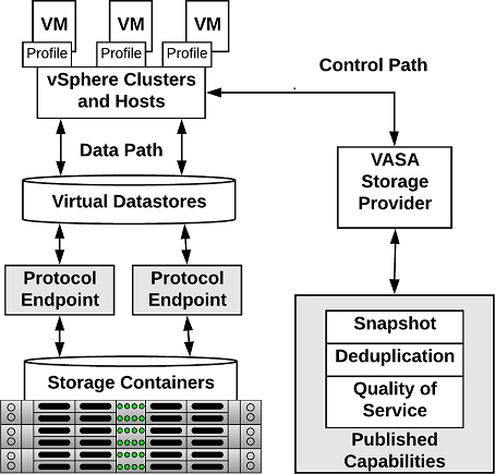
Figure 2-7 vVols Architecture
The following list contains the main characteristics of vVols.
• No File System.
• ESX manages the array through VASA.
• Arrays are logically partitioned into containers, called Storage Containers.
• Virtual Volume Objects are encapsulations of VM files and disks are stored natively on the Storage Containers.
• Storage Containers are pools of raw storage. or aggregations of storage capabilities, which a storage device can provide to vVols.
• I/O from ESXi host to the storage array is addressed through an access point called, Protocol Endpoint (PE).
• PEs are logical I/O proxies, used for communication for vVols and the virtual disk files. These endpoints are used to establish data paths on demand, by binding the ESXi hosts with the PEs.
• Bind requests must sent from ESXi hosts or vCenter Servers to before a vVol can be used.
• Data Services are offloaded to the array. Snapshot, Replication, Encryption.
• vVols are managed through storage policy-based management (SPBM) framework. VM Storage Policies are required for VMs to use vVols.
The following list provides the five type of vVols
• Config-vVol: Metadata
• Data-vVol: VMDKs
• Mem-vVol: Snapshots
• Swap-vVol: Swap files
• Other-vVol: Vendor solution specific
Limitations of vVols include the following.
• You cannot use vVols with a standalone ESXi host.
• vVols does not support Raw Device Mappings (RDMs).
• A vVols storage container cannot span across different physical arrays.
• Host profiles that contain virtual datastores are vCenter Server specific. A profile created by one vCenter Server cannot be applied by another vCenter Server.
Storage Multipathing and Failover
Multipathing is used for performance and failover. ESXi hosts can balance the storage workload across multiple paths for improved performance. In the event of a path, adapter, or storage processor failure, the ESXi host will failover to an alternate path.
During path failover, virtual machine I/O could be delayed for a maximum of 60 seconds. Active-passive type arrays could experience longer delays than active-active arrays.
• Fibre Channel Failover: For multipathing, hosts should have at least two HBAs. This is in addition to redundant fibre channel switches (the switch fabric) and redundant storage processors. If a host has two HBAs, attached to two fibre channel switches, connected to two storage processors, then the datastores attached to the SAN can withstand the loss of any single storage processor, fibre channel switch, or HBA.
• Host-based Failover with iSCSI: Similar to Fibre Channel Failover above, hosts should have at least two hardware iSCSI initiators or two NIC ports used with the software iSCSI initiator. This is in addition to at least two physical switches, and at least two storage processors.
• Array-based Failover with iSCSI: On some storage systems, the storage device abstracts the physical ports from the ESXi hosts, and the ESXi hosts only see a single virtual port. This is used by the storage system for load balancing and path failover. If the physical port where the ESXi host is attached should be disconnected, the ESXi host will automatically attempt to reconnect to the virtual port, and the storage device will redirect it to an available port.
• Path Failover and Virtual Machines: When a path failover occurs, disk I/O could pause for 30 to 60 seconds. During this time, viewing storage in the vSphere client or virtual machines may appear stalled until the I/O fails over to the new path. In some cases, Windows VMs could fail if the failover is taking too long. VMware recommends increasing the disk timeout inside the guest OS registry to 60 seconds at least to prevent this.
Pluggable Storage Architecture (PSA)
Pluggable Storage Architecture was introduced in vSphere 4 as a way for storage vendors to provide their own multipathing policies which you can install on ESXi hosts. PSA is based on a modular framework that can make use of third-party multipathing plugins, or MPPs, or utilize the VMware provided native multipathing plugin (NMP), as illustrated in Figure 2-8.
VMware provides generic native multipathing modules, called VMware NMP and VMware HPP. In addition, the PSA offers a collection of VMkernel APIs that third-party developers can use. The software developers can create their own load balancing and failover modules for a particular storage array. These third-party multipathing modules (MPPs) can be installed on the ESXi host and run in addition to the VMware native modules, or as their replacement. When installed, the third-party MPPs can replace the behavior of the native modules and can take control of the path failover and the load-balancing operations for the specified storage devices.
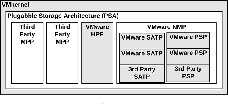
Figure 2-8 Pluggable Storage Architecture
VMware Native Multipathing Plugin
![]()
The VMware NMP supports all storage arrays listed on the VMware storage HCL and provides a default path selection algorithm based on the array type. It associates a set of physical paths with a specific storage device (LUN). NMP uses submodules, called Storage Array Type Plug-ins (SATPs) and Path Selection Plug-ins (PSPs).
The NMP performs the following operations.
• Manages physical path claiming and unclaiming.
• Registers and unregisters logical devices.
• Maps physical paths with logical devices.
• Supports path failure detection and remediation.
• Processes I/O requests to logical devices:
• Selects an optimal physical path.
• Performs actions necessary to handle path failures and I/O command retries.
• Supports management tasks, such as reset of logical devices
Storage Array Type Plug-ins (SATPs)
Storage Array Type Plug-ins (SATPs) are submodules of the VMware NMP and are responsible for array-specific operations. The SATP handles path failover for the device. ESXi offers an SATP for every type of array that VMware supports. ESXi also provides default SATPs that support non-specific active-active, active-passive, ALUA, and local devices.
Each SATP perform the array-specific operations required to detect path state and to activate an inactive path. This allows the NMP module to work with multiple storage arrays without being aware of the storage device specifics.
The NMP determines which SATP to use for a specific storage device and maps the SATP with the storage device’s physical paths. The SATP implements the following tasks:
• Monitors the health of each physical path.
• Reports changes in the state of each physical path.
• Performs array-specific actions necessary for storage failover. For example, for active-passive devices, it activates passive paths.
Table 2-10 provides details on the native SATP modules.
Table 2-10 SATP Details
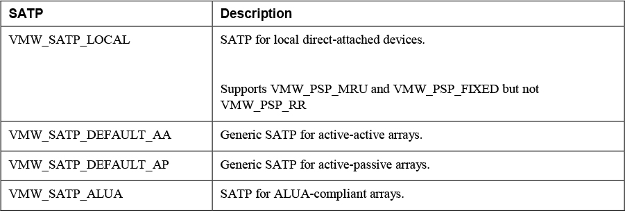
Note
You do not need to obtain or download any SATPs. ESXi automatically installs an appropriate SATP for an array you use. Beginning with vSphere 6.5 Update 2, VMW_SATP_LOCAL provides multipathing support for the local devices, except the devices in 4K native format. You are no longer required to use other SATPs to claim multiple paths to the local devices.
Path Selection Plug-ins
VMware Path Selection Plug-ins (PSPs) are submodules of the NMP. PSPs handle path selection for I/O requests for associated storage devices. The NMP assigns a default PSP for each logical device based on the device type. You can override the default PSP.
Each PSP enables and enforces a corresponding path selection policy.
Table 2-11 provides details on the native path selection policies
Table 2-11 VMware Path Selection Policies

PSA Summary
To summarize, the PSA performs the following tasks:
• Loads and unloads multipathing plug-ins.
• Hides virtual machine specifics from a particular plug-in.
• Routes I/O requests for a specific logical device to the MPP managing that device.
• Handles I/O queueing to the logical devices.
• Implements logical device bandwidth sharing between virtual machines.
• Handles I/O queueing to the physical storage HBAs.
• Handles physical path discovery and removal.
• Provides logical device and physical path I/O statistics.
The following process occurs when VMware NMP receives an I/O request for one of its managed storage devices.
1. The NMP calls the appropriate PSP
2. The PSP selects an appropriate physical path.
3. The NMP issues the I/O request on the select path.
4. If the I/O operation is successful, the NMP reports its completion.
5. If the I/O operation reports an error, the NMP calls the appropriate SATP.
6. The SATP interprets the errors and, when appropriate, activates the inactive paths.
7. The PSP selects a new path for the I/O.
When coordinating the VMware native modules and any installed third-party MPPs, the PSA performs the following tasks:
• Loading and unloading MPPs.
• Hides virtual machine specifics from MPPs.
• Routes I/O requests for a specific logical device to the appropriate MPP.
• Handles I/O queueing to the logical devices.
• Shares logical device bandwidth between virtual machines.
• Handles I/O queueing to the physical storage HBAs.
Storage Policies
Storage policies can be used to define which datastores to use when placing virtual machines disk. The following storage policies can be created:
• VM Storage Policy for Host-Based Data Services: These policies are rules for services which are offered by the ESXi hosts, such as encryption.
• VM Storage Policy for vVols: These policies allow you to set rules for VMs that apply to vVols datastores. This can include storage devices that are replicated for disaster recovery purposes or have specific performance characteristics.
• VM Storage Policy for Tag-Based Placement: You can create custom policies for VMs and custom tags for storage devices. This is helpful for storage arrays that do not support VASA and their storage characteristics are not visible to the vSphere client. For example, you could create a tag named Gold that you use to identify your best performing storage.
Storage Policy Based Management
You can define a required policy for a VM, such as requiring it to reside on fast storage. You can then utilize the vSphere API for Storage Awareness (VASA) or define storage tags manually. Then a VM can only be placed on a storage device matching the requirements.
Virtual Disk Types
When creating a virtual disk, you need to determine how you are going to allocate space to that virtual disk. The way space is allocated to a virtual disk is through writing zeroes, typically referred to as zeroing out the file. For example, if you wanted to create a 20 GB virtual disk and allocate all of the space up front, a VMDK file is created, and 20 GB worth of zeroes are written to that file. You can determine when the zeroes get written:
• Eager zeroed thick: The disk space for the virtual disk files is allocated and erased (zeroed) out at time of creation. If the storage device supports VAAI, this operation can be offloaded to the storage array. Otherwise, the VMkernel writes the zeroes, which could be slow. This method is the slowest for virtual disk creation, but the best for guest performance.
• Lazy zeroed thick: The disk space for the virtual disk files is allocated at the time of creation, but not zeroed. Each block is zeroed, on demand at run time, prior to presenting it to the guest OS for the first time. This increases the time required for disk format operations and software installations in the guest OS..
• Thin provisioned: The disk space for the virtual disk files is not allocated or zeroed at creation time. The space is allocated and zeroed on demand. This method is the fastest for virtual disk creation, but the worst for guest performance.
vSAN Specific Storage Policies
vSAN storage policies define how VM objects are placed and allocated on vSAN to meet performance and redundancy requirements. Table 2-12 defines the vSAN storage policies and their definitions.
Table 2-12 vSAN Storage Policies

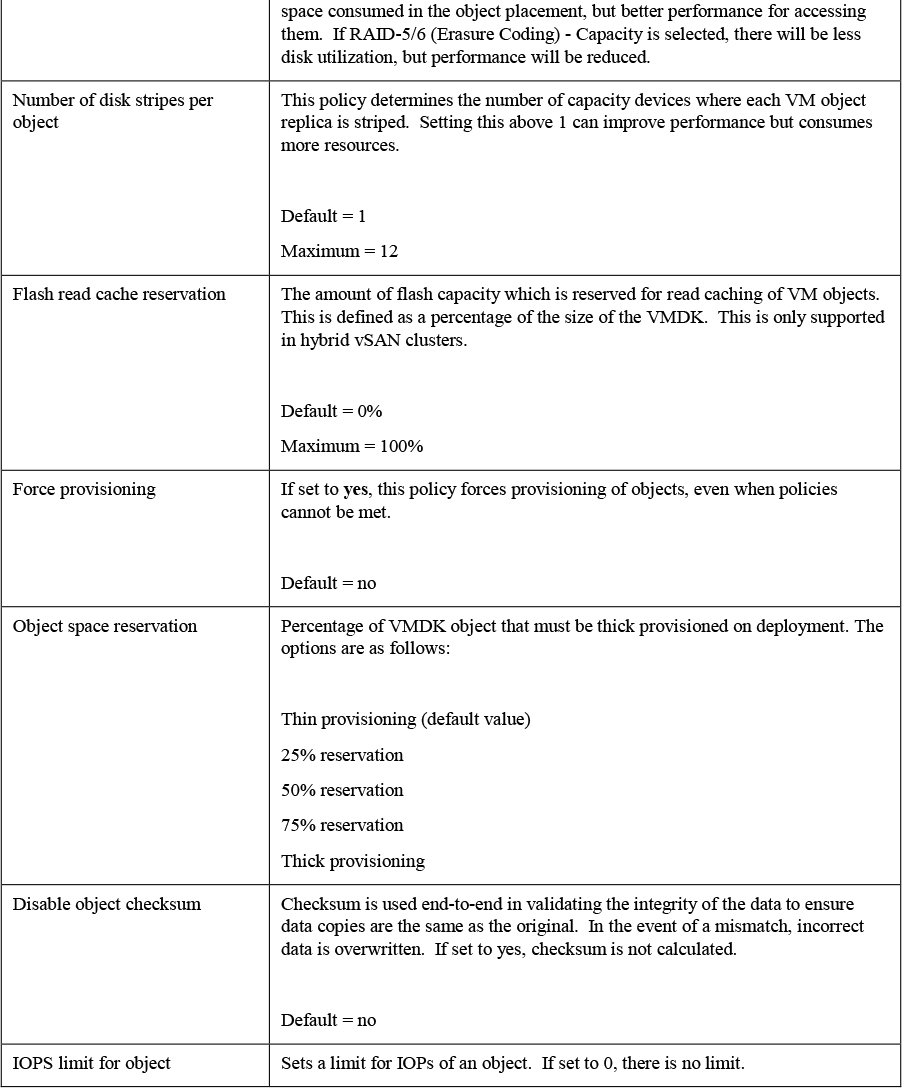
Storage DRS (SDRS)
You can use vSphere Storage DRS (SDRS) to manage the storage resources of a datastore cluster. A datastore cluster is a collection of datastores with shared resources and a shared management interface. SDRS provides the following capabilities for a datastore cluster.
Initial Placement and Ongoing Balancing
SDRS provides recommendations for initial virtual machine placement and ongoing balancing operations in a datastore cluster. Optionally, SDRS can automatically perform the recommended placements and balancing operations. Initial placements occur when the virtual machine is being created or cloned, when a virtual machine disk is being migrated to another datastore cluster, or when you add a disk to an existing virtual machine. SDRS makes initial placement recommendations (or automatically performs the placement) based on space constraints and SDRS settings (such as space and I/O thresholds).
Space Utilization Load Balancing
You can set a threshold for space usage to avoid filling a datastore to its full capacity. When space usage on a datastore exceeds the threshold, SDRS generates recommendations or automatically performs Storage vMotion migrations to balance space usage across the datastore cluster.
I/O Latency Load Balancing
You can set an I/O latency threshold to avoid bottlenecks. When I/O latency on a datastore exceeds the threshold, SDRS generates recommendations or automatically performs Storage vMotion migrations to balance I/O across the datastore cluster.
SDRS is invoked at the configured frequency (by default, every eight hours) or when one or more datastores in a datastore cluster exceeds the user-configurable space utilization thresholds. When Storage DRS is invoked, it checks each datastore's space utilization and I/O latency values against the threshold. For I/O latency, Storage DRS uses the 90th percentile I/O latency measured over the course of a day to compare against the threshold.
SDRS Automation Level
Table 2-13 describes the available SDRS automation levels.
Table 2-13 SRDS Automation Levels
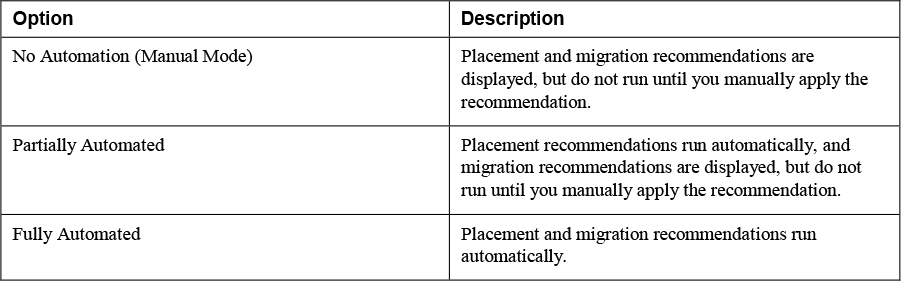
SDRS Thresholds and Behavior
![]()
You can control the behavior of SDRS by specifying thresholds. You can use the following standard thresholds to set the aggressiveness level for Storage DRS.
• Space Utilization: SDRS generates recommendations or performs migrations when the percentage of space utilization on the datastore is greater than the threshold you set in the vSphere Client.
• I/O Latency: SDRS generates recommendations or performs migrations when the 90th percentile I/O latency measured over a day for the datastore is greater than the threshold.
• Space utilization difference: SDRS can use this threshold to ensure that there is some minimum difference between the space utilization of the source and the destination, prior to making a recommendation. For example, if the space used on datastore A is 82% and datastore B is 79%, the difference is 3. If the threshold is 5, Storage DRS will not make migration recommendations from datastore A to datastore B.
• I/O load balancing invocation interval: After this interval, SDRS runs to balance I/O load.
• I/O imbalance threshold: Lowering this value makes I/O load balancing less aggressive. Storage DRS computes an I/O fairness metric between 0 and 1, with 1 being the fairest distribution. I/O load balancing runs only if the computed metric is less than 1 - (I/O imbalance threshold / 100).
SDRS Recommendations
For datastore clusters, where SDRS automation is set to manual mode (no automation), SDRS makes as many recommendations as necessary to enforce SDRS rules, balance the space, and balance the I/O resources of the datastore cluster. Each recommendation includes the virtual machine name, the virtual disk name, the datastore cluster name, the source datastore, the destination datastore, and a reason for the recommendation.
SDRS makes mandatory recommendations when the datastore is out of space, anti-affinity or affinity rules are being violated, or the datastore is entering maintenance mode. SDRS makes optional recommendations are made when a datastore is close to running out of space or when adjustments should be made for space and I/O load balancing.
SDRS considers moving powered on and powered off virtual machines for space balancing. Storage DRS considers moving powered-off virtual machines with snapshots for space balancing.
Anti-affinity Rules
If you want to ensure a set of virtual machines are stored on separate datastores, you could create anti-affinity rules for the virtual machines. Alternatively, you can use an affinity rule to place a group of virtual machines on the same datastore.
By default, all virtual disks belonging to the same virtual machine are placed on the same datastore. If you want to separate the virtual disks of a specific virtual machine on separate datastores, you can do so with an anti-affinity rule
Datastore Cluster Requirements
Datastore clusters can contain a mix of datastores having different sizes, I/O capacities, and storage array backing. However, the following types of datastores cannot coexist in a datastore cluster.
• NFS and VMFS datastores cannot be combined in the same datastore cluster.
• Replicated datastores cannot be combined with non-replicated datastores in the same Storage-DRS-enabled datastore cluster.
• All hosts attached to the datastores in a datastore cluster must be ESXi 5.0 and later. If datastores in the datastore cluster are connected to ESX/ESXi 4.x and earlier hosts, Storage DRS does not run.
• Datastores shared across multiple data centers cannot be included in a datastore cluster.
• As a best practice, all datastores in a datastore cluster should have identical hardware acceleration (enabled or disabled) settings.
NIOC, SIOC, and SDRS
In vSphere, you can use Network I/O Control (NIOC), Storage I/O Control (SIOC) and Storage Distributed Resource Scheduler (SDRS) to manage I/O. These features are often confused by people in the VMware community. Table 2-14 contains a brief description of each feature along with the chapter in this book where you can find more detail.
Table 2-14 Comparing NIOC, SIOC, and SDRS
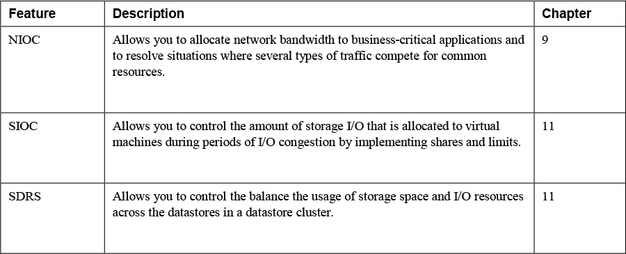
Exam Preparation Tasks
As mentioned in the section “How to Use This Book” in the Introduction, you have a couple of choices for exam preparation: the exercises here, Chapter X, “Final Preparation,” and the exam simulation questions on the CD-ROM.
Review All Key Topics
Review the most important topics in this chapter, noted with the Key Topics icon in the outer margin of the page. Table 2-15 lists a reference of these key topics and the page numbers on which each is found.
Table 2-15 Key Topics

Definitions of Key Terms
Define the following key terms from this chapter and check your answers in the glossary:
Complete the Tables and Lists from Memory
Print a copy of Appendix B, “Memory Tables,” (found on the CD), or at least the section for this chapter, and complete the tables and lists from memory. Appendix C, “Memory Tables Answer Key,” also on the CD, includes completed tables and lists to check your work.
Review Questions
1. You are deploying datastores in a vSphere environment and want to use the latest VMFS version that supports ESXi 6.5 and ESXi 7.0. Which version should you use?
a. VMFS 3
b. VMFS 4
c. VMFS 5
d. VMFS 6
2. You are preparing to manage and troubleshoot a vSAN environment. Which of the following is a is a command-line interface that provides a cluster-wide view and is included with the vCenter Server deployment?
a. VMware PowerCLI
b. vSAN Observer
c. Ruby vSphere Console
d. ESXCLI
3. You want to integrate vSphere with your storage system. Which of the following provides software components that integrate with vSphere to provide information about the physical storage capabilities?
a. VASA
b. VAAI
c. SATP
d. NMP
4. Which of the following is the default path selection policy for most active-passive storage devices?
a. VMW_PSP_MRU
b. VMW_PSP_FIXED
c. VMW_PSP_RR
d. VMW_PSP_AP
5. You are deploying virtual machines in a vSphere environment. Which virtual disk configuration provides the best performance for the guest OS?
a. Thin provisioned
b. Thick eager zeroed
c. Thick lazy zeroed
d. Thin eager zeroed