
Now that you have an understanding of the Fusion flow node and timeline editors and how they work together in a VFX workflow, it is time to get into how you fine-tune the motion over time using complex spline constructs to control the “rate of change” in time and using curves to define time interpolationmathematics.
We’ll continue working on the project created during the previous chapter in the spline editor, changing the complexity of a linear (no changes over time) movement into a more complex second-order derivative (change in rate over time) mathematical representation. We will accomplish this by using spline curves, a brilliant application of one mathematical topology to another complex endeavor (controlling time), in my most humble opinion.
Spline Editor: Control Time Using Curves
The Fusion spline editor allows you to edit the motion curves that you created in the timeline editor when you defined ranges of movement by turning on Animate and setting keyframes. To see these, click the Splinetab next to the Timeline tab, as shown in Figure 10-1 on the far right. To see a spline, select a node or node parameter that you keyframed; you’ll see motion curve data. If you check a parameter, you can edit your spline; if you put a dot in this checkbox, you will be shown a reference spline. If you leave this checkbox empty, Fusion will hide that spline. A reference spline is a spline that is visible but locked from editing.

Figure 10-1. Click the Spline tab, then select the Amplitude control
I’m also showing the Show Key Markersicon/toggle option turned on in Figure 10-1, and I highlighted the resulting keyframe triangles, shown in red. I will try to cover as many spline edit features during this chapter as I can, starting with the UI (user interface) tools and widgets. Since no nodes, or spline handles, are selected, a significant number of tool icons—at the top of the spline editor—remain dim, which means they are not active.
Navigate the Spline Editor: Independent Zooming
The spline editor allows you to zoom independently on an axis, as you can see in Figure 10-2, where I have zoomed in to the y-axis (vertical). The y-axis represents the magnitude of a change over time, whereas the x-axis (horizontal) represents the time duration itself. Compare Figure 10-2 with Figure 10-1.

Figure 10-2. Click y-axis plus to zoom in on the rate of change
Interestingly, zooming in vertically is the same as zooming out horizontally, which is shown in Figure 10-3, where the representation of the spline curve becomes even more peaked, even though I have not edited the spline itself. Zooming out on the time serves to zoom in on the rate of change (keyframe values), as you can see.

Figure 10-3. Click x-axis minus to zoom out on the rate of time
You can either click on these zoom icons, shown in Figure 10-4, or click and drag your mouse over the numbers in the X and Y margins, which label the values used in your graph.
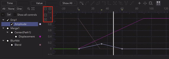
Figure 10-4. Zoom to fit splines, turn on all curve visibility
As you can see in Figure 10-4, there are colored dots in the spline header that color the splines (bright color when the spline is selected, darker color when not active). Click on one now; you will get the Spline Color Picker dialog.
Coloring the Spline Editor: Customize Spline Color
The Spline Color Picker dialog allows you to set any of 16,777,216 color values for your spline curve by selecting basic color swatches on the left or setting HSV or RGB numeric values on the right. You can also click an empty custom colorsswatch, seen on the left in Figure 10-5, to save any non-standard color you create.

Figure 10-5. A Spline Color Picker dialog
Viewing Splines: Pan, Show, and Hide Splines
You can drag splines around in the viewport in the same way that you drag things in other areas of Fusion, by using the middle mouse button to click and drag the view. You can also use the All, None, and One buttons for views that have lots of splines showing to make the workflow easier to comprehend. The All button turns on all splines for editing, as is shown in Figure 10-6.
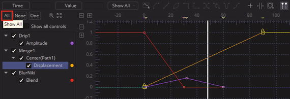
Figure 10-6. The All button turns on all splines for editing
The One button turns on one spline at a time for editing. If you select another spline for editing, a previously selected spline will be turned off. This allows you to work with splines in isolation without referencing other splines in the project, as shown in Figure 10-7.

Figure 10-7. The One button toggles individual spline display
The None button turns off all splines for editing. Why? Think of this as a reset to use before you select the One button. The Sel button turns off all splines that are not selected by the blue highlighting. This button does not affect how checkbox settings have been set by yourself, whereas the top three icons do affect those checkbox settings—All checks them all, None will uncheck them all, and One allows only one (selected) to be checked at any given time. The optimal way to get familiar with these is to use them in a VFX project. The Show all controls button, when clicked, will show all options in all nodes whether they’re keyframed or not. This is not frequently used for VFX work, as you generally only want to see what you are actually working on in any given editor (the “less is more” theory, as it were).
If you do click the Show all controls button, use it with your Sel button, as shown in Figure 10-8, so that you’re only displaying all the controls for one of the nodes you are working on.

Figure 10-8. Use the Show all controls button with the Sel button
Next, let’s take a look at how to change the spline data.
Controlling Spline Curvature: Tensioning Handles
Select the middle keyframe (top point) in your drip node, which brings the ripple effect in and out of the VFX composition. As you can see in Figure 10-9, you will get several new UI elements, including two spline tensioning handles on either side of the selected point.

Figure 10-9. Select the middle (top point) keyframe in the spline, revealing the spline editing handles
As you can see, once you select a spline node or control point, you get the keyframe (Time) value and its corresponding data value, shown in light purple. You also get two icons that allow you to turn that segment of the spline into a polygon, straight line, or curved line. These are shown highlighted in red in Figure 10-10. I have also pulled one of the tensioning handlesaway from the spline to create a control curveon that half of the spline. A spline is controlled by the handle lengthas well as the angle of the handle, so play around with this to get a feel for how it will control your spline curvature.

Figure 10-10. Pull right spline handle and create curved motion
If you now pull the other (left) tensioning handle away from the spline, you will notice that this affects the movement of the right tensioning handle to some extent. To move handles independently of each another, hold down the CTRL key (Command on Mac) on your keyboard, as shown in Figure 10-11. This will tell Fusion 8 that you want to “break” this connection between the spline handles.

Figure 10-11. Hold down CTRL key and move spline tensioning handles independently of each other
To refine a spline curve further, you can insert control points. When you mouse-over any segment of a spline, it will turn blue. Click anywhere on that segment, and insert a new control point, as is shown in Figure 10-12. Pull the tensioning handles and create a complex motion control curve for your VFX parameter.
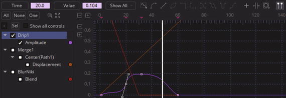
Figure 10-12. Mouse over left half of curve and click to insert a control point
There are other ways to affect spline curvature, such as using the context-sensitive menu approach that we used in Chapters 8 and 9. Select the merge node and right-click your first keyframe spline node, as seen in Figure 10-13, and select the Smooth option, which will turn the curve from the polygonal spline representation to a smooth spline curve representation.

Figure 10-13. Right-click first merge control point and then choose Smooth
You can see your smoothed Merge1 motion control curve in Figure 10-14, which now ramps the merge much more smoothly over time. This gives a more subtle but also a more believable result.
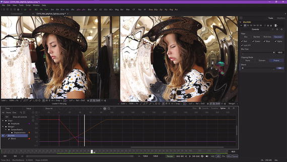
Figure 10-14. Marquee select the blur curve control points and use the time stretch tool to insert purple time-stretch handles
You can also transform several spline control points at the same time using a marquee selection, found with the other spline tools (dimmed unless multiple control points are selected) at the top of your Fusion 8 spline editor pane.
Spline Scaling Tools: Time Stretch and Shape Box
Select the BlurNiki node in the spline header area and marquee select two control points in this curve. Click the time stretchtool, shown circled in red in Figure 10-14, at the top-right of the spline editor. This will add two vertical purple bars that function similarly to the timeline editor playhead. You can drag either one and smoothly scale the time values for that segment. This essentially “stretches” time, hence the name for the tool.
There is another tool called the shape box tool that can do the same thing as the time stretch tool, but in both dimensions at the same time! Let’s look at your zoom marquee tool and use it to zoom in on this project. The tool is seen in Figure 10-15 circled in red; click to activate it, and then draw a marquee around the Drip1 node spline curve, which will put a white dotted line around the area that you want to fill your spline editor pane.

Figure 10-15. Use a zoom marquee tool to zoom into a drip curve
Once the marquee zoom is done, as shown in the top panel of Figure 10-16, this tool will turn off and you can again use your marquee select to select the last three keyframes (control points in the spline editor) on your Drip1 node. Once these are selected, click on the shape box tool, shown in the middle panel of Figure 10-16 (above the yellow popup tooltip). A control cage, complete with resizing handles, should appear around your selected Drip1 node’s (keyframes) spline control points.
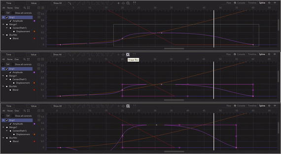
Figure 10-16. Select the shape box tool to scale time in both the X and the Y dimensions
I used the right-side cage handle to scale the curve in toward the left, and the top cage handle to scale the curve up.
Control Point Macros: Spline Curve Algorithms
If you select more than one control point on your spline curve, you will enable (unghost) the rest of the control point tools , which are essentially algorithms or “macros” that can automate some common spline editor tasks. I selected the middle two drip control points using a selection marquee, as shown in Figure 10-17, and suddenly all of the tool icons that were ghosted at the top of the spline editor became live, or activated for use.

Figure 10-17. Selecting two or more control points will enable more spline algorithm tools at the top of the spline editor
The first two, step inand step out, create basic square polygon “steps” between the two selected points, as is shown in Figure 10-18. These create jerky, rather than smooth, movement.

Figure 10-18. Use step in or step out to create polygonal lines
The next one, reverse, simply reverses your mathematical spline data. As you can see in Figure 10-19, this is not invert spline (mirror ), but rather a complete reversal of a spline’s direction .

Figure 10-19. Use reverse tool to reverse mathematical (spline) data
The last three tools create copies of the selected curve region and paste them onto the rest of the spline. Let’s take a look at these before I finish up the chapter. As you can see in Figure 10-20, I have selected the last two control points on the Drip1 node, as I want them to repeat ad infinitum to create my looping effect, just as if I had selected the Loopoption in a control panel. Click the Set Loopicon to loop the last section of the spline.
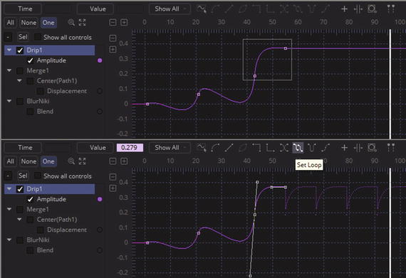
Figure 10-20. Select your last two control points for looping
Click the Set PingPongicon to loop the last section and mirror it at the same time, as can be seen in Figure 10-21. I did not see a PingPong option in the Control Panel settings I looked at in Chapter 9, so this would be a way to achieve this effect.

Figure 10-21. Click the Set PingPong icon to loop and mirror curve segment
The Set Relativeicon loops the spline segment relative to the last point, creating a staircase-like looping result, as shown in Figure 10-22.

Figure 10-22. Click the Set Relative icon to loop and offset curve segment
Summary
In the tenth chapter, we took a look at Fusion’s spline editor and spline curve concepts, tools, and algorithms (or macros). We looked at panning, zooming, selecting, and editing splines.
In Chapter 11, you will learn all about masking, polylines, and advanced concepts and techniques that are related to animated polyline masking in advanced VFX project pipelines.