Now that you have covered the advanced concepts of animated mask creation and bluescreen and greenscreen keying, let’s cover another advanced concept and technique called motion tracking. Since visual effects are often applied to video footage, this is a common feature in VFX software packages, and one that you will need to comprehend. The technology behind motion tracking algorithms is complex, but it can provide powerful tools with which you can integrate video into the VFX project pipeline.
We will look at how motion tracking is done with pattern recognitionand tracking , including what a patternis, what the search areais, how you track multiple patterns, stabilization, pattern channelsselection, adaptive pattern tracking, offsets, motion stabilization, movement matching, and positioning.
Motion Tracking: Concepts and Tools
Motion tracking is a major part of working with both VFX and 3D software packages, so this will be a good chapter for use with Fusion, which is both VFX and 3D software in one combined software package. I’ll use some videos from the sample-videos.com website and hollywoodcamerawork.com website to demonstrate motion tracking concepts using Fusion over the course of this chapter.
Track a Pattern: Algorithmic Pixel Region Analysis
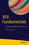
Your pattern definitionis a region of pixels that are selected for tracking in a video frame using the tracker tool in Fusion. I downloaded SampleVideo_1280x720_2mp.mp4 from www.sample-videos.com for use in showing Fusion’s basic motion tracking functionality in this section of the chapter. Open a new Fusion composition, right-click in the flow node editor, and Add Tool ➤ I/O ➤ Loader to import this sample video, shown as number 1, in Figure 13-1.
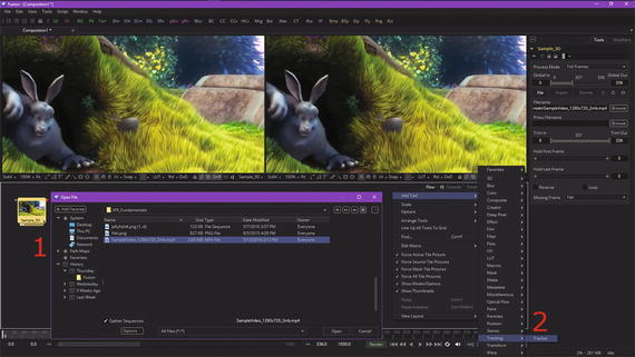
Figure 13-1. Add image loader and motion tracker nodes to a new VFX project
Right-click again in your flow node editor and use the Add Tool ➤ Tracking ➤ Trackercontext-menu sequence to add your motion tracker tool node, shown as number 2 in Figure 13-1.
The pattern definition widget will be represented in the viewer using a solid green rectangle when your tracker tool has been added, as you can see in Figure 13-2, circled in red. I’ve also found the cut in the sample video clip at frame 209, and so I set this frame as the end of this working segment, also seen circled in red at the bottom in the time ruler section.
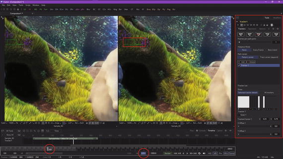
Figure 13-2. Set the working segment to end at 209 (time ruler)
A motion tracking tool can define more than one pattern, and each of your pattern definitions will produce its own path. When you first add a “virgin” tracker node to your flow editor, Fusion starts you out with one pattern displayed in the viewer using a small green rectangle.
This rectangle will turn red when it is selected, as you will soon see in Figure 13-3. When your cursor is placed over this pattern definition rectangle, the control expands, and two rectangles will appear. The outer rectangle will have a dashed line, while the inner will use a solid line. The outer rectangle is your pattern search definitionarea, and the inner rectangle is the pattern definition area.
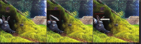
Figure 13-3. Various stages of use of pattern definition widget
If you need to select a new pattern definition area, you will move this widget by clicking on the small white box at the top left of the pattern rectangle and dragging the widget into position in the first frame (in this case) where you are going to define the pattern you want to give to this motion tracker.
Whenever you move the pattern rectangle , an overlay will appear that shows a zoomed-in version of the pixels contained within the rectangle, as is shown in the middle view in Figure 13-3.
The zoom widget is designed to help you to position the pattern definition with pixel-accurate precision. Notice that I have placed the pattern center at the tip of the bunny ear where the contrast between the light and dark pixels is the highest.
The pattern definition rectangle can also be resized by dragging on its edges. When the cursor is over the on-screen control widget for a pattern definition, a second rectangle with a dotted border should appear around the pattern definition. The outer rectangle defines the pattern search area from which a motion tracker algorithm will sample tracking data.
When processing from one frame to the next during motion tracking, the motion tracking pattern recognition algorithm will analyze the search region surrounding the last tracker position in an attempt to recognize the pattern definition in the next frame. The larger the search region definition is in pixels, the better chance the motion tracking algorithm has of successfully tracking rapidly moving patterns (subjects, objects, etc.).
On the other hand, the more pixels this algorithm has to process, the longer it will take to calculate the motion track. Therefore, there is a trade-off that you need to consider when setting the size of your search region definition (outer box).
There are some obvious ways to optimize your pixel array, which contains your search area tracking data. If you happen to be tracking an object that is moving rapidly across the screen from left to right, the algorithm will require a search area pixel array that is wide but not tall, since all the movement is horizontal. If your search area is smaller than the movement of the pattern from one frame to the next, your tracking algorithm will likely fail to find your subject (pattern) and could start tracking the wrong pixels.
It is therefore important to take the speed and direction of object motion into consideration when setting your search area. It is also interesting to note that the size of the search area can be animated over time, if that is needed for your project.
Animating the search region definition can be useful when the motion tracker pattern definition accelerates or decelerates rapidly part of the way through your source digital video clip. Now, let’s generate some motion tracking keyframes!
Create a Motion Path: Generate Tracker Keyframes
Let’s take a look at how to generate a motion path that will follow the face of the subject we are tracking. Once the pattern is selected, you can instruct a tracker to create a motion path that represents the position of your tracked scene element—in our case, it’s the tip of an ear—in each frame. Each pattern enabled in the tracker list, shown on the right in Figure 13-2, will produce its own path data; how you use this data is based on your VFX project objectives. Before instructing a tracker to create a path, you need to set your render range, during which a pattern is moving through a frame—in our case, this range is frames 0 through 209. You learned how to set the render range in Chapter 9. Once you have set the render range, you can click on any of the tracking transport buttons, seen in Figure 13-2 at the top of the Tracker1 control panel, and initiate tracking algorithm processing. Once motion tracking algorithmic processing has begun, you cannot work in the flow node editor until the motion path generation process has been completed.
I used the far right motion tracking generation button , Track Forward, with my keyframe location at zero. There is also a Track Forward from Current Time button to the left of that.
To stop the motion tracking algorithm, use the red middle button (Stop Tracking). You can even run the tracking algorithm in reverse using the Track Reverse and Track Reverse from Current Time buttons seen on the left. There are visual representations of each of these button labels on these motion tracking icons.
When I clicked the Track Forward button, using the pattern settings seen on the right-hand pane in Figure 13-3, there weren’t enough search region pixels for an algorithm to develop a motion path. Also, since the ear quickly moved onto a colored background for most of the scene, rather than staying on the dark black color, the pattern itself disappeared, at least from the perspective of the algorithm. Therefore, I switched from the ear to the chin, as seen in Figure 13-4, and adjusted my frame range from 8 to 192, as shown circled in red in the time ruler. I also enlarged the search region significantly and selected the “Best Match ”option in the algorithm’s adaptive modesetting, shown circled in red.
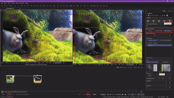
Figure 13-4. Set a new range, search area, and adaptive mode
The pattern recognition algorithm offers three different approaches (each is a different algorithm), as the “ideal” pattern, if there actually is such a thing, would almost always undergo shifts in pixel orientation, color, lighting conditions, and other “chaotic” variables present in digital video footage.
These variables can adversely affect pattern recognition to the point that a pattern will actually become unusable from the algorithm’s (mathematical) perspective. This is what happened to me with the ear pattern definition, so I changed the pattern as well as the adaptive mode that I was using for this tracker.
An adaptive mode is applied to all active patterns while the motion tracking algorithm is processing. If you only want some pattern definitions to use the adaptive mode setting, then you will need to disable all other patterns in the tracker list before tracking.
The tracker list is under the Add and Delete buttons in the area I highlighted in red on the right side of Figure 13-4.
The tracker tool offers three distinctive modes for its pattern detection algorithm, which is used during motion tracking and can help to correct for your unforeseen pattern conditions.
These modes can be set using your adaptive mode buttons, seen in the tracker control panel in Figure 13-4. When adaptive mode is set to None, a pattern within the rectangle is acquired when the pattern is selected, and that becomes the only pattern that will be used during the motion tracking. If Every Frameis chosen, the pattern in the rectangle will initially be acquired when the pattern is selected and will be acquired again on each subsequent frame. A pattern found for frame 1 will be used in a search on frame 2, a pattern found in frame 2 will be used in a search on frame 3, and so forth. This method helps the tracker’s pattern recognition algorithm adapt to changes in motion pixels over time due to lighting, shadows, color, and subject movement.
The downside to the Every Frame adaptive mode is that it is processing-intensive, as the algorithm does a lot more searching and defining of patterns. It can also has a tendency to “drift” due to sub-pixel pattern shifting from one frame to the next. Only use Every Frame adaptive mode if your other methods or settings have failed to produce the intended result.
Finally, the Best Match adaptive mode should function in the same fashion as Every Frame tracking. The difference is that Best Match, which is what I chose to use, will not redefine your pattern if the difference between the original pattern and the new pattern is too significant. Rather, it will default to your old pattern so as not to diverge onto a different (incorrect) path.
This helps to prevent the case where transient change in your video asset causes the tracker tool to become disoriented. For example, if a shadow passes over a pattern definition, your Every Frame tracking mode can start tracking the shadow instead of the defined pattern. Best Match mode should detect a change, and thus won’t grab the pattern from that frame since the difference from the previous pattern is too extreme. I changed my adaptive mode and made my search area larger, and the tracking worked!
Figure 13-5 shows the tracker output in View2 (the image loader tile was set for View1, as is seen in Figure 13-4), which shows the algorithm setting the pattern definition rectangle on each frame and rendering that portion of the video inside of it to show you what’s being done. I showed two different frames in the sequence, so you can see what your motion tracker algorithm is doing.
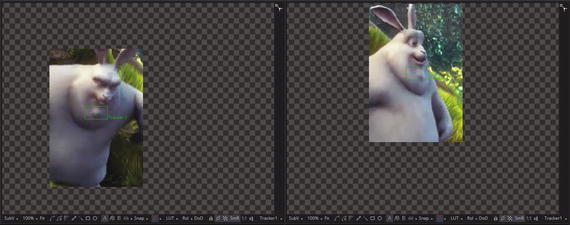
Figure 13-5. Tracker will render the search area for each frame
Once the rendering of the motion path has been completed, you will get a Render Completed dialog, as seen in Figure 13-6, along with the motion path, shown in green in both viewports.
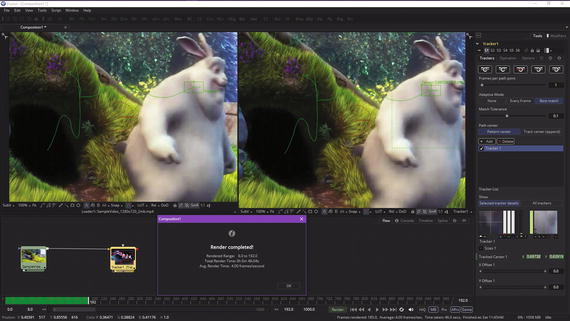
Figure 13-6. Once render is complete, you’ll have a motion path
Let’s add a couple more trackers to your bunny’s face!
Track Multiple Points: Use More Than One Tracker
Click on the Add button, shown circled in red in Figure 13-7, to add your second tracker algorithm to the tracker tool node.
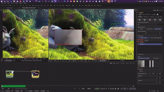
Figure 13-7. Use Add button to add additional motion tracker
Place your second tracker on the left cheek. Add a third tracker, as seen in Figure 13-8, and place it on the right eye.
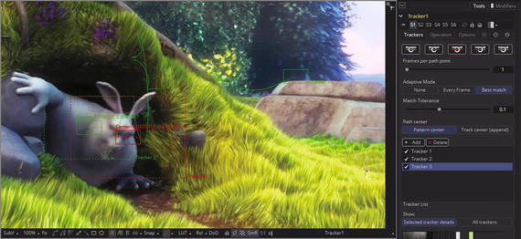
Figure 13-8. Place three motion trackers on your bunny’s face
You should add as many trackers as you need for a single tracker tool node instance. Usually, you will be tracking more than one subject in a complex VFX shot for film, television, games, or an interactive multimedia production. Figure 13-9 shown the rendering of these multiple trackers , each at the same time, in two of your search regions during the rendering sequence.
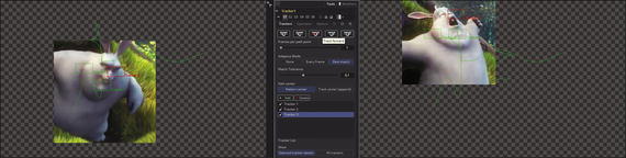
Figure 13-9. Multi-tracker rendering showing two search regions
Next, let’s take a look at tracker corner positioning.
Corner Positioning: Add Content to a Motion Track
Let’s use a four (corner) tracker scenario next, which might be used to replace a license plate on a car or picture in a frame, which is what we are going to use the tracker for next. Start a new project in Fusion and use Add Tool ➤ I/O ➤ Loader to find the hcw_picture_frame.png image series, as shown in Figure 13-10.
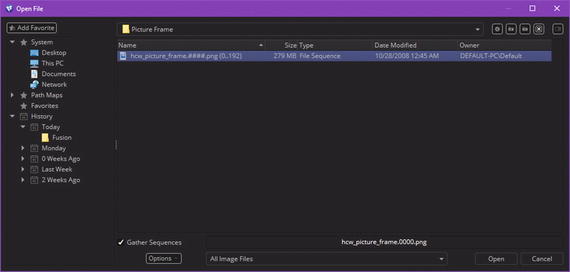
Figure 13-10. Use Add Tool ➤ I/O ➤ Loader and add the hcw_picture_frame.png image series
You can locate these files at the Hollywood Camera Work website at http://www.hollywoodcamerawork.com/trackingplates.html in the Picture Frame section. I cannot host them with the book project, due to legal terms of educational usage, but you can get the PNG series from their site, just make sure to read their legal terms!
Figure 13-11 shows the loader with the 193-frame series, as well as a tracker, which you add using Add Tool ➤ Tracking ➤ Tracker. Wire the image series into the tracker node as you did before, and then locate the tracker widget in the upper-left corner, as shown in the right view in Figure 13-11. I am showing a zoomed-in view of the widget in each of these figures so you can see just how precisely I’m positioning the tracker widgets in the corner areas of the picture frame, which we will be motion tracking.
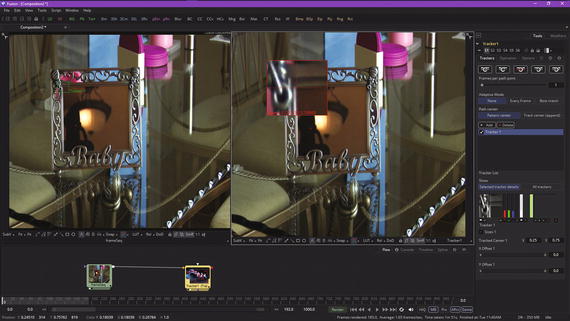
Figure 13-11. Wire up your nodes and position your first corner
The next step is to select a tracker node and configure it so that it’s using the Corner Position Operation(algorithm) and four corner tracking data trackers, both shown highlighted in red on the right side in Figure 13-12.
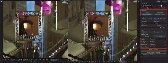
Figure 13-12. Select the Corner Positioning button
Once you select the Corner Positioning button in the Operation section, Fusion will add three more trackers, and will even connect them with a parallelogram construct, as seen in Figure 13-12, using red wires for the connections and green lines to show the tracker node’s data definition widgets.
As you can see, the next step is to position these three trackers in their respective corners so that you show the tracker the inside of the picture frame that you want to motion track. Go ahead and do this now, to get some practice in using the tracker.
I’ve shown how I positioned center-targeting crosshairs, located in the center of each zoom widget, in the corner areas of the picture frame. Once you do this correctly, all you have to do is select the correct tracking algorithm option, which is not always so easy to do, to get a good motion tracking result. As you can see in Figure 13-13, I’m also using these crosshairs to line up the inside of the picture frame, where picture meets frame, to define where I want the Niki.png model photo placed.
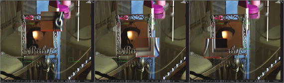
Figure 13-13. Position the other tracker widgets in each corner
The next step is to add in another image loader node for the Niki.png image that you want to track and overlay the frame with, and to add an image saver node to save out an MPEG-4 video file. Use the Add Tool ➤ I/O ➤ Saver menu sequence and save the NikiFrame.mp4 digital video asset, as is shown in Figure 13-14.
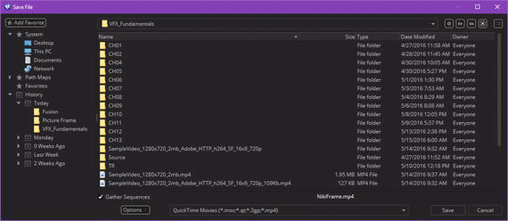
Figure 13-14. Specify QuickTime movie saver named NikiFrame.MP4
If you use the Niki.png image for your foreground input image (try it in a loader node), you’ll get a distorted result. The way I solved this was to open frame 0 of the frame image series and select the inside of the frame, and then I used the pixel dimensions to crop a matching resolution image (NikiFrame.png).
Use Add Tool ➤ I/O ➤ Loader to add the NikiFrame.png image, as seen in Figure 13-15. You can also see the image saver node and the correct tracker setting (Best Match) highlighted in red on the right side of the figure. I originally tried None, as is the recommended practice (try this first), but the corners broke away from the frame, so I tried Best Match next, which worked!
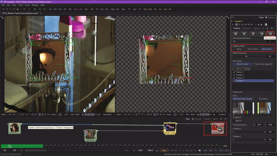
Figure 13-15. Wire the NikiFrame assets and click the Track Forward button
Use the Track Forward button to calculate your tracking path, then select the saver node tile, as seen in Figure 13-16.
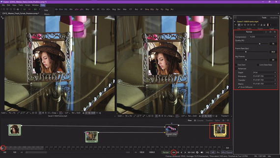
Figure 13-16. Set the MPEG-4 codec settings and reset to frame 0
As you can see in Figure 13-16, I specified MPEG-4 H.264 AVC compression with the default 75% Quality and 30 FPS with 30 keyframes. Since I am a multimedia producer, I specified 24-bit true color. I left the other settings at their defaults, which, as you will see, gave me a very clear result in only 10 MB of data.
As I am ready to render this out to the QuickTime MPEG-4 image saver node, I used the “reset to frame zero” widget, shown circled in red in Figure 13-16, to reset the project views. Then I used the File ➤ Render Managermenu sequence to open the Render Manager dialog, shown at the top of Figure 13-17.
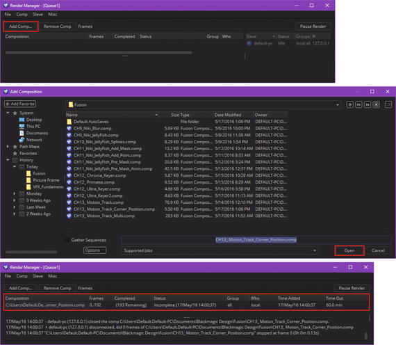
Figure 13-17. Using Render Manager and Add Composition dialogs
Click on the Add Comp button, shown circled in red. This will bring up the Add Composition dialog, seen in the middle of Figure 13-17. I added the CH13_Motion_Track_Corner_Position.comp file to this rendering queue by selecting it and clicking the Open button, which adds this current corner-position motion tracking project to the Fusion VFX project(s) rendering queue.
Once I did this, the Render Manager populated with basic information regarding the rendering operation, shown circled in red, along with any technical information such as paths, errors or issues, systems using the rendering queue, and the like. I’m showing you this in case you want to render lots of projects at the same time, or render projects you know can take a long time to render. Fusion Render Manager will render these while you’re peacefully sleeping, allowing a VFX workstation that you built during Chapter 1 to make you lots of money.
Next, let’s take a look at how to get an image saver node to save the image sequence out to an MPEG-4 H.264 AVC video file by using a File ➤ Start Render menu sequence or the green Render button found at the bottom of the time ruler user interface, located at the bottom of Fusion 8.
It is important to note that you can just use the Render button or Start Render menu option for real-time rendering; you do not necessarily need to use your render queue. I was showing you the work process as it is used for advanced (and large) VFX projects.
Once you select your Start Render menu option, the Render Settings dialog will open, shown in Figure 13-18 on the right, and you can click the Start Render button , shown circled in red. Also shown circled in red in the time ruler is a Render button that can be used as a shortcut. Once you start a render, you will see your viewports animate from frame 0 to frame 192.
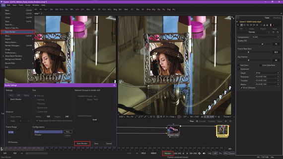
Figure 13-18. Use the Render or Start Render buttons to render
Once you click Start Render, your viewports should start showing you what Fusion is rendering out to the QuickTime codec, as you can see in Figure 13-19. If you want higher quality than the QuickTime MPEG-4 codec can provide, simply export to ProRes, DNxHD, or Sony XDcam, then use Sorenson Squeeze Desktop Pro 11 to optimize your data footprint, by applying codec compression to the project so that you have a manageable digital video asset file size.
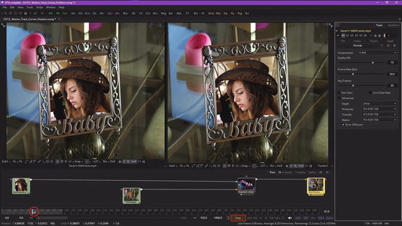
Figure 13-19. Fusion 8 viewports show each frame being rendered
As you can see in Figure 13-20, there is now a NikiFrame MPEG-4 file that is only 10 MB in my VFX_Fundamentals folder, and when I play it back I get a smooth, high-quality motion tracking VFX result. As you have seen during this chapter, motion tracking is a complex area in VFX pipeline design. You’ll have to work with it for a while in order to become familiar with it due to the number of options available, as well as your having to set the data-gathering widgets to collect the correct pixel data to process.
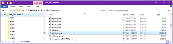
Figure 13-20. Your NikiFrame.mp4 file is generated in only 10 MB
I am trying to get into progressively more complex areas in Fusion as the book proceeds, at least during these final seven chapters, and so now we’re going to go into the third dimension and show how Fusion can bridge the realms of 2D and 3D inside the same VFX compositing engine.
With each passing chapter, you will become more and more amazed at what Fusion 8 can do for your VFX project pipeline.
Summary
In this thirteenth chapter, we took a look at motion tracking concepts, principles, and formats that can track objects through your digital image (sequence) assets and digital video assets. We looked at the Fusion tracker node (algorithm) and how it defines what data is examined on a frame-by-frame basis so as to apply pattern recognition algorithms and settings to it. The resulting motion path is used to attach objects to or to guide other algorithms in Fusion as to how to process their objectives. One of these examples used corner positioning to replace an image in an empty frame in a moving shot of that frame. We also looked at how to use an image saver, the Render Queue, and the QuickTime MPEG-4 H.264 AVC export codec to export your project using a digital video file format.
In Chapter 14, you will learn about 3D concepts and techniques as we take a look at Fusion’s 3D capabilities. The rest of this book will incorporate these 3D capabilities as well, so each chapter in the book builds upon the previous one.