
For the next few chapters we will begin to move away from the two-dimensional graphics that we have been using so far and enter the brave new world of the third dimension. Before we get too far, however, there are some new concepts and approaches that you need to become familiar with.
Three-dimensional rendering introduces a variety of new challenges: 3D graphics are rendered as models rather than as simple bitmaps, our brains need to shift into a different gear to keep track of movement in and out of the screen, and we have an entirely different way of telling XNA where we want to draw things on the screen.
We will examine some of these changes in this chapter so that you can fully understand the environment in which you need to work in order to draw 3D graphics. This chapter doesn't get too involved in the actual 3D rendering; we'll cover that in Chapter 7, but everything contained here is essential to know in order to be able to effectively use XNA's 3D rendering technology.
Let's start by discussing some of the features of the 3D rendering environment.
All the graphics that we have rendered in the chapters up to this point have been based around sprites. They were configured by using a series of simple properties to define their position, rotation, scaling, and coloring. This gave us a simple mechanism for putting sprites wherever we needed them.
As we prepare to render 3D graphics, we leave this approach behind for the time being (though don't forget it entirely because we can use sprites and 3D graphics together, as discussed in Chapter 8). Instead, we use a system based around matrices.
Matrices allow us to encode a series of movements and transformations into a compact structure that can then be applied to the graphics that we want to draw. Most of the calculations required to do this are conveniently wrapped up in handy XNA functions, so we don't need to get too involved in their inner workings.
Just like anything else, it might take a little time to become accustomed to thinking with matrix transformations, but once you do you will find them a very useful tool. In fact, you might ultimately decide that you prefer them to XNA's sprite rendering approach.
When we render in 3D, XNAgenerally uses an abstract coordinate system rather than a pixel-based coordinate system like the one used for sprite rendering, meaning that we are not concerned with pixels. Although this might sound like a disadvantage at first, freeing ourselves from pixel coordinates actually turns out to be rather useful.
When we initialize XNA, we can tell it the dimensions of the screen and the coordinate system will scale to match. Moving a graphic object a certain distance to the right, therefore, moves the same distance regardless of the back buffer size. As a result, should we decide to use a smaller buffer to increase performance, none of the rendering code needs to change (as it did when we were rendering sprites).
Note
3D rendering with a pixel-based coordinate system is also an option if you want. This will be discussed in the "Orthographic Projection" section in Chapter 7.
After all the time we have spent with sprites, getting to grips with the 3D coordinate system requires a slight twist of the brain. First of all, the coordinate (0, 0) is generally right in the center of the screen rather than in the top-left corner. Second, movement along the positive y axis will travel up the screen, as opposed to down for sprites. It can be a nuisance having to keep these two conflicting coordinate systems in your brain, but once you are in the frame of mind for one system over the other, it should be easy to remember which way is up.
Becausewe are now using a 3D graphical environment, we actually need to add a third element to our coordinates. The coordinate values we have looked at in the past have been in the form of (x, y), representing the specified distances along the x and y axes. 3D coordinates are in the form (x, y, z), providing values in the z axis as well as the x and y axes. The z axis represents movement into or out of the screen—literally the third dimension. Positive values on the z axis result in movement toward the player, negative values result in movement into the screen.
When it comes to drawing graphics, XNA is actually not able to draw anything more complex than triangles. This might at first seem very restrictive, but in fact, it is not as you will see when we start to use it in some example projects.
The reason we can create more complex scenes is partly because much more complex shapes can be created by putting lots of triangles together (for example, a rectangle is just two triangles joined along their long edge) and partly because we can put graphic images onto the triangles. As a simple example, we can display graphics that work along very similar lines to the sprites from earlier chapters by simply rendering a rectangle with a graphic displayed across it.
When we are drawing, we refer to each triangle as a surface. The points that form the triangle are called vertices. Figure 6-1 shows two triangular surfaces created using four vertices. Two of the vertices are shared between the triangles.

The vertices themselves are not actually displayed by XNA, just the surfaces that they define; the vertices are shown in Figure 6-1 just to clarify what they are.
The only primitives available other than triangles are lines.
Just as we used Texture2D objects to provide graphics for our sprites, so we can use them to fill the triangles that we are rendering. We have a lot of flexibility to use textures within our applications—much more so than we had with sprites. We can take small rectangular sections just as we did with sprites, or we can stretch textures in a variety of different ways across the shapes that we draw. We'll look at some of the tricks and techniques that we can use when texturing in the "Applying Textures" section later in this chapter.
Whereas, with sprite rendering, each individual call to draw graphics provided all the information needed for drawing to take place, the approach for 3D rendering is slightly different. XNA maintains lots of state values for things such as which texture is currently being used for rendering, whether transparency is enabled, whether lighting is switched on, and so on.
In order for our rendering to appear as we expect, each of these states must be set prior to the rendering call. Once a state has been set, it will stay with its value until we decide to change it again.
Note
All this actually applies to sprite rendering, too, except that the sprite engine always sets the state values according to the parameters passed to the SpriteBatch.Draw and DrawString methods. Under the covers, the rendering of sprites is using exactly the same approach described in this chapter.
Before we get into too much more detail, let's see what is involved in setting up a simple project that uses the new rendering approach. Some of the code that we will work through here will be unfamiliar and we will gloss over some of it for the time being just so that we can get some code running. All this will be explained in much more detail during the rest of this and the following chapters.
The full source code for this project can be founzd in the ColoredSquare example accompanying this chapter.
We start off by creating a new XNA project, exactly as we have always done. For simplicity, we will work in isolation of the game framework at the moment, so don't worry about adding a reference to it or changing the game class derivation; it can continue to derive from Microsoft.Xna.Framework.Game for this example.
We need to add some class-level variables to the game class to manage the scene that we wish to render. The required declarations are shown in Listing 6-1.
Example 6.1. Variables required for the scene to be rendered
private BasicEffect _effect;
    private VertexPositionColor[] _vertices = new VertexPositionColor[4];
Next we need to set up these variables ready for them to be used by XNA. The code required for this is added to the Initialize function.
The first thing we do here is set up the projection matrix. This is something that we will discuss in more detail in the next chapter, but for the moment we can consider its main task as being to set up the abstract coordinate system. As you can see in Listing 6-2, the screen's aspect ratio is determined by dividing the viewport width by its height, and this ratio is one of the values used to initialize the matrix. This ensures that objects remain square when drawn on the screen.
Example 6.2. The beginning of the Initialize function, creating the projection matrix
protected override void Initialize()
    {
        // Calculate the screen aspect ratio
        float aspectRatio =
                (float)GraphicsDevice.Viewport.Width / GraphicsDevice.Viewport.Height;
        // Create a projection matrix
        Matrix projection = Matrix.CreatePerspectiveFieldOfView(MathHelper.ToRadians(45),
                                                                aspectRatio, 0.1f, 1000.0f);
Note how the matrix is being initialized by calling one of the shared methods of the Matrix structure. There are dozens of such methods that allow us to create all kinds of matrices, as you will see as we progress.
The next step is to create the view matrix. This can be likened to a camera within the scene, and controls which objects rendered are visible and where they appear on the screen. Our example project's view matrix is created as shown in Listing 6-3. Once again, this will be discussed in more detail later.
Example 6.3. Initializing the view matrix
// Calculate a view matrix (where we are looking from and to)
        Matrix view = Matrix.CreateLookAt(new Vector3(0, 0, 10), Vector3.Zero, Vector3.Up);
Now we need to create an effect object to tell XNA how it should render our graphics to the screen. All rendering needs an effect of some kind, and several are provided for the Windows Phone 7 implementation of XNA. We'll look at some of the interesting things that they can achieve in Chapter 8, but for the time being we will use the BasicEffect to allow us to render without doing anything fancy.
The effect object is passed a reference to our graphics device when it is instantiated, and we then set a series of properties to control how it will behave. These are some of the state values that were discussed at the beginning of this chapter. Listing 6-4 shows the creation and initialization of the effect object. Note that among the values passed are the projection and view matrices that we have just constructed.
Example 6.4. Creating and initializing the effect object
_effect = new BasicEffect(GraphicsDevice);
        _effect.LightingEnabled = false;
        _effect.TextureEnabled = false;
        _effect.VertexColorEnabled = true;
        _effect.Projection = projection;
        _effect.View = view;
        _effect.World = Matrix.Identity;
The environment is now fully initialized. We don't yet have anything to draw, however, so we need to take care of this before we can render anything.
As mentioned earlier, XNA expects us to define our objects using vertices. It can then use them to construct the solid triangles that form the graphics we see on the screen.
Vertices can hold various pieces of information. They will always hold a position, but in addition to that they might contain color information, texture information, and other data that affects the way they are drawn. XNA provides some built-in configurations for common vertex structures, and the one we will use here is called VertexPositionColor. As its name implies, it stores position and color information, and nothing more.
We will get our example to draw a simple square on the screen. To tell XNA about the square, we must set up an array of vertex objects, telling it the position and color of each. Figure 6-2 shows the vertices that we will be using to form this square. The coordinate (0, 0, 0) is right in the middle of the square, and it extends 2 units across the x and y axes (from - 1 to 1 on each axis). Note that the z coordinate is left at 0 for all the vertices so that the square remains flat.

The vertices are constructed within the program code by setting their coordinates into the _vertices array that we declared back in Listing 6-1. The code is shown in Listing 6-5.
Example 6.5. Setting the vertex positions to form a square
_vertices[0].Position = new Vector3(-1, −1, 0);
        _vertices[1].Position = new Vector3(-1, 1, 0);
        _vertices[2].Position = new Vector3(1, −1, 0);
        _vertices[3].Position = new Vector3(1, 1, 0);
Just as we used Vector2 structures for providing positions for sprites, so we now use Vector3 structures to declare positions in three-dimensional space.
The final part of our initialization is to provide a color for each vertex. This will produce an attractive effect when it is rendered—and also one that we could not easily achieve using sprites without having to generate a texture containing the different colors. The remaining vertex initialization, and the conclusion of the Initialize function, is shown in Listing 6-6.
Everything is fully initialized now and we're ready to draw the square to the screen. Because we are only using vertex colors without textures, there is nothing to read in the LoadContent function, so we can leave this alone. We have nothing to update at the moment, either, so let's move straight on to the Draw function.
The screen is cleared (to CornflowerBlue once again) as it was for sprites, but the approach we take to drawing now is very different. Instead of the SpriteBatch object, we use the BasicEffect that we created earlier to manage the drawing for us.
Each effect can contain one or more techniques. These are the specific rendering operations that are contained within the effect—the effect acting as a container for one or more techniques. Each of the effects provided with XNA for Windows Phone 7 contains just a single technique, so we don't need to pay much attention to this. We will just use the default technique that the effect provides for us.
Finally, each technique contains one or more passes that perform the actual rendering to the screen. If the rendering of an effect needs to perform multiple updates to the content of the screen in order to render, there will be multiple passes returned from the technique, each of which will need to be drawn. BasicEffect uses only one pass, but just for good form we will set our code to loop for all passes that might be returned from the effect, to save confusion later on when we do encounter multiple-pass effects.
Bearing all that in mind, the code required to render the square is shown in Listing 6-7. Once the pass has been determined, its Apply method is called to tell XNA to activate it. The code then calls DrawUserPrimitives, telling it the type of primitive that it is rendering, and passing various details about what to draw. The parameters for the DrawUserPrimitives function are as follows:
primitiveTypecontains the type of primitive that we wish to draw. In this case, we draw aTriangleStrip. The available primitives will be discussed in the next section.vertexDataallows us to pass the array of vertices that we have defined.vertexOffsetis a value that allows us to start considering the vertices at a position within the array other than its start. We are not using this, so we just pass 0.primitiveCountis the number of primitives that we are drawing. As we specified that XNA should draw triangles, setting this to 2 means to draw 2 triangles. Remember that this is counting primitives, not vertices.
The code for the Draw function is shown in Listing 6-7.
Example 6.7. Drawing the colored square
protected override void Draw(GameTime gameTime)
    {
        GraphicsDevice.Clear(Color.CornflowerBlue);

        foreach (EffectPass pass in _effect.CurrentTechnique.Passes)
        {
            // Apply the pass
            pass.Apply();
            // Draw the square
            GraphicsDevice.DrawUserPrimitives(PrimitiveType.TriangleStrip, _vertices, 0, 2);
        }

        base.Draw(gameTime);
    }
The resulting graphic can be seen in Figure 6-3.
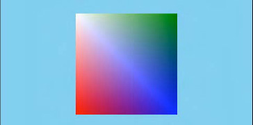
Notice how XNA has handled the colors within the rendered square. Each vertex is colored exactly as we had requested, but between them XNA performs a smooth fade between the colors. This is known as color interpolation and is something that you will see again in the future: any vertex parameters such as colors that differ from one vertex to the next will result in a smooth fade as XNA renders between them. This can be very useful and attractive, as this example demonstrates.
The section titled "Understanding Matrix Transformations" later in this chapter will fully cover the approach to moving our objects, but to make things a little more interesting than a static square, let's take a quick preview and get our square to spin around on the screen.
To achieve this, we first need to track the rotation angle. We will do this by adding a class-level float variable named _angle, and will update it by 5 degrees each update, as shown in Listing 6-8.
Example 6.8. Updating the angle of the square
protected override void Update(GameTime gameTime)
    {
        // Allows the game to exit
        if (GamePad.GetState(PlayerIndex.One).Buttons.Back == ButtonState.Pressed)
            this.Exit();

        _angle += MathHelper.ToRadians(5);

        base.Update(gameTime);
    }
To apply the angle to the square, we need to update the world matrix (full details of which will be provided in the "Understanding Matrix Transformations" section). Because we want to rotate the square, we need to give it a rotation matrix. XNA's Matrix class provides various methods for creating such a matrix, and the one we will select for our example is the CreateRotationZ function. This function accepts a single parameter (the rotation angle) and returns a matrix ready for us to use.
The updated code to draw the square with rotation is shown in Listing 6-9.
Example 6.9. Rotating and drawing the colored square
protected override void Draw(GameTime gameTime)
    {
        GraphicsDevice.Clear(Color.CornflowerBlue);

        // Set the world matrix so that the square rotates
        _effect.World = Matrix.CreateRotationZ(_angle);

        foreach (EffectPass pass in _effect.CurrentTechnique.Passes)
        {
            // Apply the pass
            pass.Apply();
            // Draw the square
            GraphicsDevice.DrawUserPrimitives(PrimitiveType.TriangleStrip, _vertices, 0, 2);
        }

        base.Draw(gameTime);
    }
Note that the call toDrawUserPrimitives that is actually drawing the square is completely unchanged; it is the state of the effect that is causing the object to rotate, not the instruction to draw. This is clearly different to the approach we used with sprite-based rendering.
Of course, this rotating square only scratches the surface of what we can achieve with XNA. Let's make a simple change to the project that results in a dramatic and attractive enhancement to the displayed graphics.
If we modify the Draw code so that it is as shown in Listing 6-10, we will see that it has a significant effect on the graphics that are drawn to the screen, as shown in Figure 6-4. The code for this can be found in the NestedSquares example project.
Example 6.10. Rendering the square in the NestedSquares example project.
protected override void Draw(GameTime gameTime)
    {
        GraphicsDevice.Clear(Color.CornflowerBlue);

        // Reset the world matrix
        _effect.World = Matrix.Identity;

        // Loop for each square
        for (int i = 0; i < 20; i++)
        {
            foreach (EffectPass pass in _effect.CurrentTechnique.Passes)
            {
                // Apply a further rotation
                _effect.World = Matrix.CreateRotationZ(_angle) * _effect.World;
                // Scale the object so that it is shown slightly smaller
                _effect.World = Matrix.CreateScale(0.85f) * _effect.World;

                // Apply the pass
                pass.Apply();
                // Draw the square
                GraphicsDevice.DrawUserPrimitives
                                        (PrimitiveType.TriangleStrip, _vertices, 0, 2);
            }
        }

        base.Draw(gameTime);
    }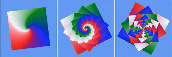
The screen shots sadly don't do justice to the effect project in operation; it is much better in motion than in still images, but this gives an idea of the patterns that this tiny piece of code is able to generate.
All that the loop is doing is drawing 20 shapes instead of one, each of which is slightly smaller than the last and rotated to a different angle. The scale and rotate operations are cumulative, meaning that, although the first (largest) square is rotated by the angle specified in _angle, the second square is rotated by double this angle, the third by three times the angle, and so on.
One of the useful features we explored when using sprites is the ability to tint the sprite into a different color. The same facility is available when rendering objects using vertices, too.
The effect object has a property named DiffuseColor, which allows the tint color to be set. This property defaults to white, which leaves the colors of our objects unchanged, but can be modified to any color that we desire. The color is applied to our vertex colors just as it was for sprites: it takes the red, green, and blue values of each vertex color and represents them as a value between 0 and 1. Each of them is then multiplied by the corresponding color element within DiffuseColor, and the resulting values used for the final vertex color.
Setting DiffuseColor to black will therefore result in all vertex colors becoming black, too. Setting DiffuseColor to red will remove all green and blue color information from the vertices, resulting in just the red color elements surviving.
Unlike the color properties we have seen so far, however, DiffuseColor is implemented as a Vector3 structure rather than as a Color. Each of the three elements within the Vector3 relates to one of the color elements in a color: the x element stores the amount of red, the y element stores the amount of green, and the z element stores the amount of blue. All three of these measure color using a float value in the range of 0 to 1, rather than an integer from 0 to 255.
To make our lives easier, the XNA developers have taken into account the need to translate color values between the Color structure and the Vector3 structure and have provided built-in functions to accomplish this.
To convert a Color into a Vector3, simply call its ToVector3 method. The resulting vector values will match those of the color. A simple example of this can be seen in Listing 6-11.
Example 6.11. Converting a Color structure into a Vector3
Vector3 myColorVector;
        myColorVector = Color.PeachPuff.ToVector3();
To convert a Vector3 into a Color, create a new Color and pass the Vector3 as a parameter to its constructor. This will produce a color whose values match that of the vector. A simple example of this is shown in Listing 6-12.
Example 6.12. Converting a Vector3 structure into a Color
Vector3 myColorVector = new Vector3(1.0f, 0.8f, 0.2f);
        Color myColor;
        myColor = new Color(myColorVector);
Try modifying the NestedSquares example project so that the effect's DiffuseColor is set prior to rendering the squares in the Draw method and see the effect that it has on the generated graphics.
Being a Vector3, however, this gives no opportunity to set an alpha value. When we tinted sprites, alpha values were also available and allowed us to fade the transparency of the sprites that were being rendered. In the vertex-rendering approach, it is still possible to change the alpha of rendered objects, but this is controlled using a separate property. This will be discussed in the "Object Transparency" section later in this chapter.
Let's take a closer look at what is happening when we move the shape that we are drawing.
Within XNA, the position at which we will draw graphics is tracked using the worldmatrix.A matrix is a set of values, arranged in rows and columns, which can be applied to the coordinates of our vertices in order to move them around on the screen.
By combining multiple matrices, movement operations can be grouped together. For example, we might want to move an object 1 unit to the right and then rotate it by 45 degrees. To do this, we start with an empty matrix, apply the movement matrix, and then the rotation matrix. The resulting matrix can be used to transform any vertex coordinate so that it moves 1 unit to the right and rotates by 45 degrees. There is no need to separately apply the movement and rotation to each vertex because the transformation matrix will perform both steps in one calculation.
This allows for transformations to be built up into greater and greater levels of complexity, but doesn't make calculating the point onscreen at which each vertex will be drawn any more difficult or processor-intensive.
Exactly how these matrices are created, manipulated, and applied is not something that we will cover in any detail in this book. There are plenty of online references that will explain this subject in further detail; for example, see http://en.wikipedia.org/wiki/Matrix_(mathematics) for information on what a matrix is, how matrices and constructed, and how arithmetic operations are performed; and http://tinyurl.com/matrixtransform to read about how matrix transformations work at a mathematical level.
We will discuss how matrix transformations are actually used in practical terms. Though the numerical representations of transformations might be somewhat abstract, visualizing what each transformation will do is somewhat easier.
We have already discussed the fact that XNA maintains state for lots of properties that affect how it will render to the screen, and that one of these is the world matrix. Each time we begin drawing, a world matrix of some description will already be set, usually from a previous call to Draw, and we won't necessarily have any idea what it contains. We should therefore always ensure that the world matrix is set prior to performing any drawing.
In order to reset this matrix to its initial state, we set the matrix to a preset set of values called the identity matrix. This ensures that any rendering that takes place will initially be centered at the origin—at coordinate (0, 0, 0)—and will not be rotated or scaled at all.
We can obtain an identity matrix at any time from the static Matrix.Identity property. To render objects without any transformation, set it as the effect's world matrix prior to applying the effect passes. You can see this being used at the beginning of Listing 6-10.
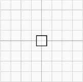
A square with a width and height of one unit can be seen in Figure 6-5 after the identity matrix has been applied. It is directly centered on the origin of the coordinate system.
In the terminology of matrix transformations, moving an object along one or more of the axes is called a translation. The shape, size, and angle of the object are entirely unchanged; the object is just moved left or right, up or down, and in or out of the world to a new position.
Figure 6-6 shows the effect of a translation matrix. The image on the left shows the unit square in position after the identity matrix has been loaded; the image on the right shows the same square after it has been translated 3 units in the x axis and −2 units in the y axis. (For simplicity, we will ignore the z axis for the moment, but transformation along the z axis is achieved in exactly the same way as for the x and y axes.)

To obtain a translation matrix, call the static Matrix.CreateTranslation function. This function has a couple of overloads: the first requires three parameters (the translation distance for the x, y, and z axes, respectively); the second accepts a single Vector3 parameter.
Both of them have their uses depending on the way you want to specify your movement. The Vector3 approach is very handy because it allows a movement path to be stored (just as we did in two dimensions for the rocks in the Cosmic Rocks examples from the previous chapters) and easily transformed into a translation matrix.
Note
The Matrix.CreateTranslation function has two different calling styles: one that returns its generated matrix as a return value from the function, and another that returns the matrix in an output parameter. All the other matrix generation functions share these two approaches. Feel free to use whichever you are more comfortable with, but in the text of this book we will use the versions that return matrices as their return values.
We can also rotate the objects that we draw. Objects can be rotated around any of the three axes, as shown in Figure 6-7.

Rotation around the x axisis around a horizontal line drawn across the screen. If you held a sheet of paper in front of you so that you were looking directly at the flat face of the paper, rotation on the x axis would rotate the paper so that the bottom edge was brought toward you and the top edge away, resulting in you looking at the paper's front edge.
Rotation on the y axis is exactly the same, but rotating around a vertical line.
Z axis rotation is around a line that traces a path into and out of the screen. This is the axis of rotation that we have used in the ColoredSquare and NestedSquares example projects.
To obtain a matrix to rotate around one of these axes, call one of the following static functions:
Matrix.CreateRotationXto rotate around the x axisMatrix.CreateRotationYto rotate around the y axisMatrix.CreateRotationZto rotate around the z axis
All three functions require the rotation angle to be passed as a parameter (in radians).
Note
Rotating around the z axis will result in counterclockwise rotation. To rotate clockwise, simply negate the rotation angle.
Rotation around other axes can also be achieved by using the Matrix.CreateFromAxisAngle function. It requires two parameters: an axis vector defining the line around which the rotation is to take place and the rotation angle.
To calculate the axis vector, imagine the rotation axis as a line that passes through the origin point at (0, 0, 0). Then determine a point that is on that line and provide its coordinate as the values for the vector.
For example, if we want to rotate around a line that slopes upward at a 45-degree angle, we can visualize it passing through the origin point, as shown in Figure 6-8. The figure shows a point that has been selected on the line at coordinate (2, 2, 0), though any point on the line would be fine. This coordinate forms the values for the axis vector.

One important detail must be taken into account for the axis vector, however: it must be normalized. If it is not, the objects will warp and distort as they rotate around it. Listing 6-13 provides an example of using the CreateFromAxisAngle function to rotate around the line from Figure 6-8.
The last of the transformations that we will be working with for the time being is for scaling the objects that we render. Scaling matrices can be either uniform, in which case the object scales by the same amount on all three axes; or non-uniform, in which case each axis scales by a different amount.
Figure 6-9 shows an object in its identity location on the left, with a uniform scale of 2.0 in the middle, and then on the right with a scale of 4.0 on the x axis and 0.5 on the y axis.

To obtain a scaling matrix, call the static Matrix.CreateScale function. It has three calling methods: it can be passed a single float to perform a uniform scale, it can be passed three floats to perform a non-uniform scale with the values provided for the x, y, and z axes; or it can be passed a Vector3 containing the values for non-uniform scaling.
Passing a scale value of 0 for any of the axes will squash the shape on that axis so that it is completely flat. It can be easy to accidentally pass this when you had intended to leave the scaling unchanged for an axis; for any axis that you want to leave unchanged when scaling, pass a value of 1.
Negative scale values are also permitted. These will cause the object to flip over so that the vertices appear on the opposite side of the negatively scaled axis.
To apply a single transformation to our objects, we can simply obtain the required matrix and set it into the effect's World matrix property. We have already seen several examples of this.
Any practical application of matrix transformations will quickly find that setting the matrix for just a single transformation is insufficient, however. If we need to perform multiple transformations at once (for example, perhaps we need to move the object to another point within the world and then rotate it), we need some way to combine these transformations together.
Fortunately, matrix transformations are perfectly suited to this task. We can combine two or more transformations by simply multiplying the matrices together. The resulting matrix will contain the effects of both of the input matrices.
The different types of translation can have an effect on each other that might not at first be obvious, so let's first look at the effects of applying multiple transformations. We will then come back to look at how they are implemented in code.
When we rotate an object, we actually rotate its entire coordinate system because we are transforming the entire world, not just the object itself. If the identity matrix is loaded, the world coordinates are reset so that the origin point (0, 0, 0) is in the center, and no scaling or rotation is applied. Once we begin to transform this matrix, the coordinate system moves around accordingly.
Objects always move relative to the transformed coordinate system, not to the identity coordinate system. This means that, if we rotate an object by 45 degrees around the z axis and then translate it along the y axis, it will actually move diagonally onscreen rather than vertically. The rotation has changed the direction of the axes within the world coordinate system.
The effects of this rotation can be seen in Figure 6-10. On the left is the usual unit square at the identity position. In the middle, we rotate it by 45 degrees around the z axis (counterclockwise). The pale lines show the x and y axes in the identity coordinate system, whereas the darker diagonal lines show the x and y axes for the transformed world coordinate system. On the right, we translate it along its y axis. Observe that it has moved diagonally relative to the identity coordinates, though it has followed the transformed world y axis. Also note that the world coordinate system follows the translation, too. The coordinate (0, 0, 0) moves along with the translations that are applied to the world matrix.

This sequence of updates brings us to another important feature of matrix transformations: the order in which they are applied is significant. In Figure 6-10, we first rotated and then translated our object. If we instead translate and then rotate it, the coordinate system for the translation would still be aligned with theidentity coordinate system, so the movement on the screen would be vertical. This is shown in Figure 6-11, which contains exactly the same transformations but performed with the translation before the rotation.

As you can see, the object ends up in a different place if we translate it first.
This is actually very easy to visualize. Imagine that you are standing in place of the square object in these diagrams. You are initially standing at the origin of the identity coordinate system, looking along the positive y axis (up the screen).
You then decide to rotate 45 degrees counterclockwise, just as in Figure 6-10. You are still facing straight ahead of your body, but relative to the identity coordinates, you are now looking diagonally. If you now take a few paces forward, you are walking diagonally in terms of the identity coordinates but straight ahead in terms of your own position within the world.
If you hold your arms out to the sides, they will be pointing along the x axis relative to your position but are once again at a diagonal angle relative to the identity coordinates.
Any time you want to visualize the transformations that you are applying, think of this same scenario and apply each transformation in sequence to yourself in the world. It should then be easy to see the sequence of transformations that you need to apply to get from one place to another. (It gets slightly harder to visualize in three dimensions, but just imagine you have wings or a jet-pack.)
Hopefully, this makes the effects of cumulative transformations clear. Always remember that, when you transform an object, the transformation will be relative to the existing transformed coordinates, not to those of the identity coordinate system.
When we scale an object, the transformation once again has an effect on the world coordinate system. If we scale an object so that its size doubles, a movement of one unit in the x axis in the transformed world coordinate system will correspond to a movement of two units relative to the identity coordinate system.
If you simply want to draw an object at a different size but without affecting its position, remember to perform the scale transformation after all the translations have been completed to avoid affecting the movement distances.
So we know that multiple transformations can be combined by multiplying them together, so let's see some sample code to achieve this in XNA.
The first transformation that we want to use can be obtained directly by calling the appropriate static Matrix function. From that point on, subsequent transformations must be obtained and multiplied by the existing calculated matrix.
To translate an object two units along the y axis and then rotate it by a specified angle, we would use the code shown in Listing 6-14. It causes the object to rotate on the spot a short distance away from the center of the screen.
Example 6.14. Multiple transformations: translation and then rotation
// First translate...
        _effect.World = Matrix.CreateTranslation(0, 2, 0);
        //...then rotate
        _effect.World = Matrix.CreateRotationZ(_angle) * _effect.World;
Notice the order of multiplication: the new transformation is on the left of the multiplication symbol, and the existing matrix is on the right. Unlike multiplication of simple numbers, matrix multiplication is not commutative, which is why the order of transformations is significant. If we multiply matrix A by matrix B, we will get results different from multiplying matrix B by matrix A.
We can swap the order of these transformations so that we first rotate and then translate along the (rotated) y axis, as shown in Listing 6-15.
Example 6.15. Multiple transformations: rotation and then translation
// First rotate...
        _effect.World = Matrix.CreateRotationZ(_angle);
        //...then rotate
        _effect.World = Matrix.CreateTranslation(0, 2, 0) * _effect.World;
Even though we are generating the same matrices with the same parameter, the resulting behavior is different. Instead of spinning on the spot, the object now rotates around a circular path, centered at the identity origin and with a radius of two units (because this is the distance that the object was translated).
Try plugging each of them into the ColoredSquare project in place of the existing matrix code to see their effects.
We are not limited to using transformation types just once within a transformation sequence, of course, and some movement paths will require the same transformation to be applied repeatedly at different stages of the calculation.
For example, let's get the object to trace a circle as in Listing 6-15, but this time the circle will be away from the identity origin, and the object itself will remain "upright" without rotating at all. This is achieved using the transformations shown in Listing 6-16.
Example 6.16. Repeatedly transforming to achieve a more complex movement path
// First translate to the center of the circular path
        _effect.World = Matrix.CreateTranslation(0, 3, 0);
        // Rotate the object towards the current position on the circular path
        _effect.World = Matrix.CreateRotationZ(_angle) * _effect.World;
        // Translate to the edge of the circle
        _effect.World = Matrix.CreateTranslation(0, 2, 0) * _effect.World;
        //...then rotate back to an upright position
        _effect.World = Matrix.CreateRotationZ(-_angle) * _effect.World;
This time the circular path is centered at (0, 3, 0) because we translate to here before rotating. Then the object is rotated toward the point on the circle at which it will be rendered. The object is then translated to the edge of the circle; as the translation is two units along the (rotated) y axis, this will be the radius of the circle. Finally, to keep the object upright, it is rotated back by its angle. This cancels out the rotation that was applied in the original rotation. The original rotation therefore results in having an effect on the position of the object but not its final angle.
As you can see, this entire series of events is eventually contained in the single _effect.World matrix. There is no limit to the number of calculations that can be accumulated into a single matrix in this way.
You might recall that, when we looked at the ColoredSquare example back in Listing 6-5, the code defined the square'svertices by specifying four vertices with coordinates at (−1, −1, 0), (1, −1, 0), (−1, 1, 0), (1, 1, 0).These coordinates are, of course, interpreted relative to the world matrix, not the identity coordinate system.
When we use transformations to manipulate the world matrix, this resulting matrix is applied to each individual vertex when rendering, which causes the object to actually move onscreen. Because the coordinate system has been moved, rotated, and scaled relative to the world, all the vertex positions are transformed in exactly the same way. We can, therefore, define any shape we like using these vertex coordinates, and it will move around the screen as specified by our matrix transformations.
The example code in the projects we have looked at has always set the world matrix before looping through the effect passes and calling the Apply method on each. This is important because it is the world matrix that is present at the point of calling Apply that will be used for the subsequently rendered objects.
If you want to draw multiple objects within the same call to Draw (as you will undoubtedly want to!), you need to ensure that a call to the effect pass's Apply is made after each object's world matrix is set into the effect. Any changes made to the world matrix after this will be ignored.
There are two sequences with which this can be implemented. The first is to loop for the effect passes for each object, repeating the loop for each subsequent object. The second is to loop through the passes just once, applying each one multiple times and drawing each object after its matrix has been applied.
The first of these approaches can be seen in Listing 6-17. The effect loop is present twice, once for each of the objects being rendered. Each effect pass is applied once per loop.
Example 6.17. Drawing multiple objects with an effect pass loop per object
// Draw the first object
        foreach (EffectPass pass in _effect.CurrentTechnique.Passes)
        {
            // Set the world matrix
            _effect.World = Matrix.CreateRotationZ(_angle);
            // Apply the pass and draw
            pass.Apply();
            GraphicsDevice.DrawUserPrimitives
                                        (PrimitiveType.TriangleStrip, _vertices, 0, 2);
        }

        // Draw the second object
        foreach (EffectPass pass in _effect.CurrentTechnique.Passes)
        {
            // Set the world matrix
            _effect.World = Matrix.CreateRotationZ(_angle * 2);
            // Apply and draw
            pass.Apply();
            GraphicsDevice.DrawUserPrimitives
                                        (PrimitiveType.TriangleStrip, _vertices, 0, 2);
        }
The second approach is shown in Listing 6-18. It loops through the effect passes just once, but applies each one multiple times (once per object being rendered).
Example 6.18. Drawing multiple objects with a single effect pass loop
// Draw the objects
            foreach (EffectPass pass in _effect.CurrentTechnique.Passes)
            {
                // Set the world matrix for the first object
                _effect.World = Matrix.CreateRotationZ(_angle);
                // Apply the pass and draw
                pass.Apply();
                GraphicsDevice.DrawUserPrimitives
                                        (PrimitiveType.TriangleStrip, _vertices, 0, 2);

                // Set the world matrix for the second object
                _effect.World = Matrix.CreateRotationZ(_angle * 2);
                // Apply the pass and draw
                pass.Apply();
                GraphicsDevice.DrawUserPrimitives
                                        (PrimitiveType.TriangleStrip, _vertices, 0, 2);
            }
These code samples produce exactly the same visual results. The one you use is entirely up to you; you might find that one approach or another better fits in with the object structure that you are rendering. The important thing to remember is that the pass.Apply method needs to be called each time an updated world matrix needs to be observed.
There is one area where the two approaches will result in a performance difference, however. When we begin to apply textures to our objects (which we will examine in the "Applying Textures" section later in this chapter), we will need to pass the texture graphics to the graphics hardware each time we draw an object. Moving the graphic around in memory is a relatively expensive process because graphic files can be quite large.
We can therefore optimize our rendering by loading each texture into the graphics hardware just once and then drawing all objects that use that texture together. The next texture can then be loaded and its objects drawn. This way, we load each texture only once per draw, rather than potentially once per object.
The second rendering approach, shown in Listing 6-18, is potentially less efficient for textured objects. If we have multiple passes in our effect and each of the objects rendered has a different texture, we will end up alternating between the two textures. The first approach in Listing 6-17 deals with the object in its entirety before moving on to the next object, allowing its texture to be used by all the passes without needing it to be reloaded.
All the drawing in our examples has been handled by making a call to the GraphicsDevice.DrawUserPrimitives function. The first parameter passed to this function, the primitiveType parameter, has always been PrimitiveType.TriangleStrip. There are several values that we can pass here, so let's take a look at each and discuss what they do and how they are used.
There are two different mechanisms provided for drawing lines on the screen: PrimitiveType.LineList and PrimitiveType.LineStrip.
LineList will work through the supplied vertices, taking each pair as the beginning and end coordinate of a line. The lines do not need to be connected (and indeed, if they are it might be more efficient to use the LineStrip drawing mode). The DrawUserPrimitiveprimitiveCount parameter specifies how many lines are to be drawn. Because each line requires two vertices, the vertex array must contain at least twice the number of entries as the specified primitive count.
Figure 6-12 shows the lines drawn between four vertices using the LineList mode primitive type, and a primitive count of 2.

LineStrip is similar, but instead of working through pairs of vertices, it takes each new vertex and draws a line between it and the previous vertex. The result is a line drawn betweenall the specified vertices, as shown in Figure 6-13. The first line requires two vertices, but each subsequent line requires just one more. As a result, the vertex array must contain at least primitiveCount + 1 elements.

XNA does not offer a line drawing mode that automatically reconnects the final vertex back to the first vertex (to create a line loop). If such rendering is required, a final additional vertex will need to be added to the end of the LineStrip whose position matches that of the first vertex.
You can easily see the effects of drawing lines by modifying the ColoredSquare project to use the line primitive types instead of its existing TriangleStrip type. Notice how the vertex colors are still observed when drawing lines, and the line color fades between the color of each connected vertex.
There is no facility for setting the width of the line: all lines will be drawn with single-pixel thickness. If you need to draw lines thicker than this, you will need to simulate lines by drawing long thin rectangles formed from a pair of triangles instead.
The remaining drawing primitives provide two different methods for creating triangles. Triangles are by far the most common type of object drawn in XNA, so these primitive types will become very familiar. The available triangle primitive modes are PrimitiveType.TriangleList and PrimitiveType.TriangleStrip.
The TriangleList primitive takes each set of three vertices as an individual triangle, allowing multiple isolated triangles to be drawn. Figure 6-14 shows how six vertices are used to build two triangles using this mode. Because each triangle requires three vertices, the vertex array must contain at least three times the number of entries as the specified primitive count.

The TriangleStrip primitivereuses vertices within the vertex array to create multiple triangles, each of which shares an edge with the previous triangle. The first three vertices are used to create the first triangle; after that, the next triangle is formed by removing the earliest vertex in the triangle and replacing it with the next vertex. The first triangle is, therefore, formed from vertices 0, 1, and 2; the second triangle from vertices 1, 2, and 3; the third triangle from vertices 2, 3, and 4; and so on.
As long as you can arrange your triangles so that they share their edges in this way, the triangle strip is a very efficient way of drawing because the shared vertices need to be transformed only once even though they are used by as many as three different triangles.
Figure 6-15 shows an example using the TriangleStrip to join a series of vertices.The first triangle requires three vertices, but each subsequent triangle requires just one more. As a result, the vertex array must contain at least primitiveCount + 2 elements.

The TriangleStrip mode is perfectly suited for drawing squares and rectangles because they are formed from two triangles that share an edge. As more complex objects are encountered, however, the ability to model them using triangle strips soon becomes difficult or impossible, and for them a triangle list will be required instead.
If you have used earlier versions of XNA or are familiar with DirectX or OpenGL, you might be expecting to find a further primitive type known as a triangle fan. It defines a series of triangles that all share a single vertex, allowing that vertex to be calculated just once for the entire object. Support for triangle fans was removed in XNA version 4.0 (as used on Windows Phone 7), so this primitive type is no longer available for use.
When you are defining your triangles, you will need to be aware of XNA's hidden surface culling. This is a feature that prevents it from having to draw unnecessary triangles. We'll discuss this in more detail in the "Hidden Surface Culling" section in the next chapter, but for now just be aware that you need to ensure that the vertices of your triangle are defined so that they are in clockwise order when you look at the triangle front on. You will observe that both of the triangles shown in Figure 6-14 are defined in this way.
For triangle strips, however, this would appear to present a problem: as each triangle shares its vertices with the previous triangle, the points alternate between clockwise and counterclockwise order. This can be seen in Figure 6-15: the first triangle (consisting of vertices 0, 1, and 2) is defined in clockwise order, but the second (vertices 1, 2, and 3) is counterclockwise. XNA realizes this and takes it into account automatically; the important thing is to ensure that the first triangle in a triangle strip is defined in a clockwise direction.
Unlike earlier versions of XNA, support for drawing points (individual pixels) to the screen using vertices has been removed. To simulate drawing points, you will need to instead draw very small triangles, rectangles or lines.
Generally point drawing is of limited use anyway, so this will hopefully not present too much of a problem for your games.
Colored shapes are all very nice, but they're not generally what we need when we are creating a game. For our games, we want to be able to display graphics onscreen. How do we do this with XNA when rendering with vertices?
Fortunately, it is very easy to do so. First, we need to load a texture and then we tell XNA to display that texture on the triangles that it draws. The following sections show how this is done.
Even though we can render 3D objects when we render with vertices, the graphics that we apply to them are still 2D bitmap graphics. The graphics are wrapped around the 3D objects as if they were stickers that we are applying to a solid object.
Textures are therefore added to the Content project and loaded ready for use by our 3D objects using the exact same code as we used when loading textures for sprites.
Alpha channels and color keys can still be used with textures just as they were with sprites, but there is a wide range of different ways that we can process them. These will be discussed in the "Using Transparency and Alpha Blending" section later in this chapter.
When we are ready to render with our texture, we first need to instruct XNA to use the texture. Just as with the other state properties inside XNA, it will remember the specified texture until we tell it to use a different texture. The code in Listing 6-19 tellsXNA to use our loaded texture for subsequent textured objects.
When we rendered triangles using colored vertices, we specified a color for each vertex. Now that we are rendering with textures, we instead tell each vertex to map to a point within the texture instead.
You will recall that sprite rendering allowed us to render either the entire texture across the surface of the sprite or a subsection of the texture. When we render using vertex buffers we can also render subsections of the texture, although we achieve this in a different way. We can also distort or stretch the texture in a variety of ways that were not available to sprites.
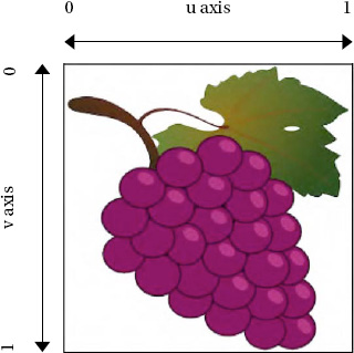
Just as coordinates on the screen are measured using axes called x and y, textures have axes called u and v. The u axis covers the distance across the width of a texture, whereas the v axis covers the distance across its height.
Note
If you are familiar with OpenGL, you might expect the texture axes to be called s and t. Although XNA uses the letters u and v instead, the function and purpose of these axes are identical to the axes in OpenGL.
Regardless of the resolution of the graphic that has been loaded, the u and v coordinates will scale from 0 to 1, where 0 represents the left edge of the u axis and the top edge of the v axis, and 1 represents the right edge of the u axis and the bottom edge of the v axis, as shown in Figure 6-16. This is a very useful feature because it lets you switch between high- and low-resolution textures without needing to modify your code in any way.
When we want to draw using texture mapping, we provide a (u, v) coordinate for each vertex that tells it the position within the texture that should be applied at that vertex. Just as colors are interpolated between the vertices of rendered objects, so too are texture coordinates. The area inside the triangle formed by the texture coordinates will be stretched to fill the triangle formed onscreen by the vertex coordinates. This can be seen in Figure 6-17, which shows a triangle along with its vertex coordinates, the positions of those coordinates on a texture, and the resulting textured triangle.

Figure 6.17. A triangle and its texture coordinates, their positions on a texture, and the resulting textured triangle
Although the vertices are specified in three dimensions and therefore contain three values per vertex, texture coordinates are reading from a 2D image. So we provide just two values per vertex: the u and v coordinates for that vertex to use. They are provided to each vertex in a Vector2 structure. Because the Vector2 uses X and Y for its property names, we will use the X property to store the texture's u value and the Y property to store the texture's v value. The value is stored in the TextureCoordinate property of each vertex.
But hold on—the vertex structure that we have been using doesn't have a TextureCoordinate property! This is because we have been using the VertexPositionColor vertex structure, which (as its name suggests) can only store a position and a color for each vertex. To store texture coordinates, we need to switch to a different structure that supports texture information. We will use the VertexPositionTexture structure, which stores position and texture information.
Note
You could alternatively use the VertexPositionColorTexture structure, which has properties for both colors and texture coordinates. This will allow a texture and per-vertex colors to be used together.
In the TexturedSquare example project, you will see that the _vertices array has been modified to use this new structure, as shown in Listing 6-20.
Example 6.20. The _vertices array using the VertexPositionTexture structure
private VertexPositionTexture[] _vertices = new VertexPositionTexture[4];
To draw a square so that it displays the entire texture mapped on it, we specify u and v coordinates of (0, 1) for the bottom-left corner; (1, 1) for the bottom-right corner; (0, 0) for the top-left corner; and (1, 0) for the top-right corner. Each of these coordinates is specified for the vertex's TextureCoordinate property. Listing 6-21 contains the code required to initialize the vertex positions and texture coordinates for such a texture mapped square object.
Example 6.21. Creating a square from two triangles and displaying an entire texture on its surface
_vertices[0].Position = new Vector3(-1, −1, 0);
        _vertices[1].Position = new Vector3(-1, 1, 0);
        _vertices[2].Position = new Vector3(1, −1, 0);
        _vertices[3].Position = new Vector3(1, 1, 0);

        _vertices[0].TextureCoordinate = new Vector2(0, 1);
        _vertices[1].TextureCoordinate = new Vector2(0, 0);
        _vertices[2].TextureCoordinate = new Vector2(1, 1);
        _vertices[3].TextureCoordinate = new Vector2(1, 0);
Alternatively, we can specify just a section of the texture that we want to map. Remember that the physical vertex coordinates are completely unaffected by this; all we are doing is specifying the area of the texture that will be applied to the object. If we provide texture coordinates that cover only a smaller portion of the texture image, this portion will be stretched to fit the shape being drawn.
Figure 6-18 shows an example of using a subsection of the texture in this way. The texture coordinates span from 0 to 0.5 along both the u and v axes.
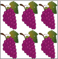
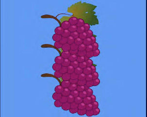
Another feature of the texture coordinates is that they are not restricted to staying within the range of 0 to 1. If we specify coordinates outside of this range, we can get the texture to repeat within our rendered graphics. Figure 6-19 shows a square object rendered with values from 0 to 3 on the u axis and 0 to 2 on the v axis. This might not be so useful when our texture is a bunch of grapes, but if you use a texture that tiles seamlessly (maybe a pattern of bricks or a stone texture), this can be a very handy way of filling the entire body of the object with a relatively small source image repeated over and over again.
The final thing we need to do is tell the XNA effect that we want it to use texture mapping. In the earlier examples, we told the effect to observe the vertex coloring by setting its VertexColorEnabled property to true. This time we will set it to false and instead set its TextureEnabled property to true. The complete effect initialization code for texturing is shown in Listing 6-22.
Example 6.22. Configuring the effect for texture mapping
_effect = new BasicEffect(GraphicsDevice);
        _effect.LightingEnabled = false;
        _effect.VertexColorEnabled = false;
        _effect.TextureEnabled = true;
        _effect.Projection = projection;
        _effect.View = view;
        _effect.World = Matrix.Identity;
Note
If you want to use the VertexPositionColorTexture structure to combine texturing and coloring, you will, of course, need to set both the VertexColorEnabled and TextureEnabled properties to true.
Our Draw code remains entirely unchanged. Because we have set the state of the effect object to use textures and provided a reference to a texture we have loaded, and we have provided texture coordinates for each vertex, XNA will automatically apply the texture to the object when it draws.
The TexturedSquare example project contains all the code needed to get this up and running; an image from the running example is shown in Figure 6-20. Try experimenting with the texture coordinates to get a feel for how they work. Some things that you can try to achieve with these are the following:
Provide a texture coordinate range that spans only part of the texture (for example, ranging from 0 to 0.5 instead of from 0 to 1) and observe how the texture is stretched across the square.
Provide texture coordinates outside of the range of 0 to 1 (for example, 0 to 3) and observe how the texture is squashed and repeated across the square.
Provide coordinates that don't correlate with the position of the vertex and observe how the texture is distorted and stretched to fit within the rendered object.

When XNA renders your texture, it queries a set of values known as the sampler state in order to fine-tune the resulting graphics. There are a couple of properties that we might want to change within the sampler state to alter the way in which the textures are processed.
The sampler state data can be read from the SamplerStates property of the GraphicsDevice object. This actually returns a collection of SamplerState objects, but the object at index 0 is the one that XNA will use for rendering.
However, the properties of this object are all read-only once the object has been attached to a GraphicsDevice (which it has by the time we can query it), and attempting to set one will result in an exception being thrown.
To change the sampler state properties, we must instead create a new SamplerState object, set its properties, and then set it into the SamplerStates collection. Listing 6-23 shows how this is achieved.
Example 6.23. Providing a new SamplerState object for XNA
// Create a new SamplerState object
        SamplerState samplerstate = new SamplerState();
        // Set its properties as required...
        // (set properties here)
        // Give the object to XNA
        GraphicsDevice.SamplerStates[0] = samplerstate;
The SamplerState class also provides a series of static properties that return preinitialized SamplerState objects in various configurations. If one of them matches your needs, you can set it directly into the SamplerState collection without having to instantiate and configure it yourself. The available preconfigured sampler states are AnisotropicClamp, AnisotropicWrap, LinearClamp, LinearWrap, PointClamp, PointWrap. The purpose of each of these will become clear once you have read through the following sections.
It is important to remember not to create new SamplerState objects during each Update or Draw because this will quickly cause garbage collection problems as we discussed earlier. If you need to use multiple sampler states within your drawing code, create them all once during initialization and just reuse these existing objects when drawing.
The first SamplerState properties that we might want to set are the texture address mode properties. Back in Figure 6-19 we saw a texture with a coordinate range that causes the texture to be repeated across the object when the texture coordinates exceed the range of 0 to 1. This is known as Wrap mode, and it is the default behavior of XNA.
There are two other modes available, however: Clamp and Mirror. The Clamp mode tells XNA to observe texture coordinates only in the range 0 to 1. Any texture coordinate that falls outside of that range will be clamped back into the range (in other words, all values greater than 1 will be treated as if they were 1, and values less than 0 will be treated as if they were 0).
The primary effect is that the texture will not wrap within the rendered object. The secondary effect is that any texture coordinate that does fall outside of the 0 to 1 range will stretch out the pixel at that texture boundary for the whole of the clamped area. In other words, setting a horizontal texture coordinate range of 0 to 2 with clamping would display the texture as normal in the left half of the rendered object, and would then stretch the pixels from the right edge of the texture image across the whole of the right half of the rendered object.
The same texture coordinates shown in Figure 6-19 are shown again in Figure 6-21 with a Clamp address mode active.

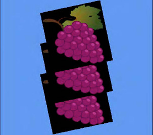
The final mode, Mirror, works very much like Wrap, except that every alternate repeat will be flipped back to front (on the u axis) or upside down (on the v axis). The same texture can once again be seen in Figure 6-22 with Mirror addressing active.

The addressing modes can be set independently for each axis, so if you want you can mirror horizontally and wrap vertically. The horizontal address mode is set using the RenderState.AddressU property, and the vertical address mode is set using the RenderState.AddressV property.
The other sampler state property that we might want to set is the Filter property. This specifies the mechanism with which XNA will enlarge and shrink textures as it renders them to the screen. Three options are available: Linear, Point, and Anisotropic.
The Point filter is primarily noticeable when enlarging textures so that they are rendered at greater than their native size. When XNA uses a point filter, it determines for each pixel rendered on the screen which of the underlying texture pixels most closely matches in position. This texture pixel color is then directly displayed on the screen. The result is that the resulting graphic becomes very pixelated and blocky, reminiscent of early 3D games before dedicated graphics hardware became commonplace.
The Linear filter (which is active by default) is a little clever when it comes to enlarging textures. Instead of directly mapping texture pixels onto the screen, it blends together the surrounding pixels to approximate a smooth blend of the underlying texture pixels. This is not magic, of course, and the image will quickly become blurry, but it generally provides a substantially better result than the Point filter.
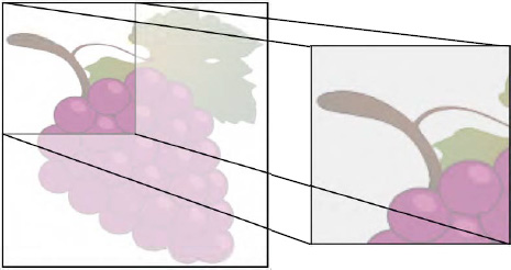
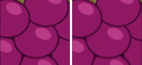
Figure 6-23 shows the textured square from in the earlier example projects, but greatly zoomed in. On the left it is rendered with a point filter and on the right with a linear filter.
The final filter, Anisotropic, comes into play when textures are being rendered so they stretch off into the distance of the screen. The perspective transformation (which we will examine in the next chapter) will result in the texture in the distance appearing much smaller than the texture in the foreground.
Linear filtering can cause noticeable visual artifacts to appear on texture that are rotated in this way. They are particularly noticeable when the texture is moving toward the player because it would be on the road in a racing game, for example. Using an anisotropic filter in this environment would provide the same general results as the linear filter, but with these texturing artifacts lessened so as to be much less apparent.
XNA is happy to apply any of its supported image types to your objects, so textures can be provided in BMP, PNG, and JPG formats. However, due to the way that the graphics hardware handles textures, you will find under some conditions your texture pixel width and height must exactly match a power of 2 (1, 2, 4, 8, 16, 32, 64, 128, 256, and so on).
The images do not need to be square, so you can, for example, use a texture that is 32 × 256 pixels, but for maximum flexibility they must observe these restrictions.
Images with sizes that are not powers of 2 can still be used in XNA provided that the texture address mode on the appropriate axes is set to Clamp, as described in the previous section. This will allow the texture to be displayed, but it means that wrapping and mirroring the texture cannot be supported on that axis.
If you want to use other texture address modes, and your texture dimensions are not powers of 2, you have a couple of options available.
First, you can enlarge or shrink your texture using a graphics editing application so that its dimensions are powers of 2. The easiest way to handle this is to stretch (or shrink) the graphic to fit the new dimensions. This gives you the greatest degree of control over the final image size and the way in which your graphic is manipulated to fit within its new space.
The second option is to get Visual Studio to automatically resize your image when compiling. This is by far the easiest approach, but does reduce the amount of control you have over the process. In many cases this will be quite sufficient, however.
To instruct Visual Studio to resize the image for you, edit the properties of the image within the Content project. Inside the Content Processor section you will find a property called Resize to Power of Two, as can be seen in Figure 6-24. Simply set this to True, and the image will be expanded to the next power of 2 on each axis when the content project is compiled.

In the TexturedSquare project, the single texture is set into the effect's Texture property as soon as it is loaded, and this stays active for the entire duration of the project.
In any real game it is highly likely that you will need multiple textures so that different objects can be drawn with different appearances on the screen.
This is easy to achieve. Once all the textures have been loaded, each one can be activated as needed within the Draw function by setting the effect's Texture property before applying the passes of the effect.
As mentioned earlier, setting the active texture is one of the most expensive things you can do in terms of performance, and so you should try to batch up your drawing so that all objects for each texture are drawn together. Avoiding setting the texture unnecessarily within each draw will help to ensure that your game performs the best it can.
The MultipleTextures example project demonstrates drawing two objects together, each with a different texture. The code from its Draw function is shown in Listing 6-24.
Example 6.24. Drawing multiple objects, each using different textures
// Activate the first texture
        _effect.Texture = _texture1;
        // Apply a transformation to move and rotate the object
        _effect.World = Matrix.CreateRotationZ(_angle);
        _effect.World = Matrix.CreateTranslation(0, 1.2f, 0) * _effect.World;
        foreach (EffectPass pass in _effect.CurrentTechnique.Passes)
        {
            // Apply the pass
            pass.Apply();
            // Draw the square
            GraphicsDevice.DrawUserPrimitives(PrimitiveType.TriangleStrip, _vertices, 0, 2);
        }

        // Activate the second texture
        _effect.Texture = _texture2;
        // Apply a transformation to move and rotate the object
        _effect.World = Matrix.CreateRotationZ(_angle);
        _effect.World = Matrix.CreateTranslation(0, −1.2f, 0) * _effect.World;
        foreach (EffectPass pass in _effect.CurrentTechnique.Passes)
        {
            // Apply the pass
            pass.Apply();
            // Draw the square
            GraphicsDevice.DrawUserPrimitives(PrimitiveType.TriangleStrip, _vertices, 0, 2);
}XNA offers us support for dealing with transparency when we render our graphics. We can achieve various effects with this, such as removing transparent parts of an image or drawing an image so that it is semitransparent, allowing the graphics behind to show through. This is known as alpha blending.
The examples we have looked at so far in this chapter have rendered images with solid black backgrounds. As you will see, alpha blending allows us to remove this and observe the alpha channel within the texture, just as we did for sprites in the earlier chapters.
In this section we'll look at the available alpha blending options and learn how you can customize them for your games.
In order to take advantage of alpha blending, we need to instruct XNA to use a blend state object. This contains information that XNA will use to determine exactly how to mix the pixels of the objects that it is drawing with the pixels that are already present on the screen.
This might be as simple as determining whether to completely replace an existing pixel or leave it with its current color, or it might involve a blend of the existing pixel and the pixel from the rendered object.
The active BlendState object can be found in the GraphicsDevice.BlendState property. The object can be interrogated, but its properties cannot be updated: just like the SamplerState objects we saw in the last section, a BlendState object's properties all become read-only once it has been set into the GraphicsDevice.
To alter the active BlendState, we must create a new BlendState object, configure its properties, and only then pass it to the GraphicsDevice, as can be seen in Listing 6-25. Once again, it is important to avoid doing this inside your Update or Draw functions: any required BlendState objects should instead be created just once during initialization and then reused as and when needed.
Example 6.25. Creating and activating a new BlendState object
// Create a new BlendState object
        BlendState blendState = new BlendState();
        // Set blend state object properties
        //...
        // Set the object into the GraphicsDevice
        GraphicsDevice.BlendState = blendState;
To disable alpha blending, the BlendState property should be set to BlendState.Opaque, as shown in Listing 6-26. There are two reasons why it is very important to remember to disable alpha blending as soon as you have finished with it. First, alpha blending has a higher processing overhead on the graphics hardware than opaque rendering because it needs to consider the pixels already on the screen as well as those being rendered. Second, having blending active when you are not expecting it to be can produce very confusing results in your game, causing objects to become transparent or even disappear.
There are some transparency effects that are more frequently used within games than others, and to simplify using these effects XNA provides a series of static objects whose properties reflect this. Before we get into the complexities of how alpha blending actually works, let's take a look at some of these states and describe the purpose and use of each. We will look at how the blend states work under the covers later in this section.
Throughout this section we will describe colors and alpha values as float values rather than as integers. This means that they will always be in the range of 0 to 1, rather than 0 to 255. The reason for this will become apparent later in the section.
You can experiment with these blend states by opening the AlphaBlending example project and changing the state that is set at the end of the Initialize function.
The BlendState.Opaque reference that we saw in Listing 6-26 is not an enumeration as it might at first appear, but is in fact one of the built-in blend state objects. Opaque is a static property on the BlendState class that returns a BlendState object configured with alpha blending disabled.
This is the default blend state that is active when your XNA game launches, and is therefore the state that we have been using so far through this chapter.
With opaque blending active, every pixel rendered from the source texture will be written to the screen so that it entirely replaces the content that is already present.
Figure 6-25 shows the Grapes texture rendered using the opaque blend mode.
A particularly useful blend state is AlphaBlend, which is actually the mode that we were using with sprites when an alpha channel or a color key was present. This mode reads the alpha value from the source texture and uses it to determine how opaque the pixel should be when rendered on top of the existing graphics.
Pixels whose alpha values are 0.0 within the texture will be rendered entirely transparent (invisible). Pixels whose alpha values are 1.0 are rendered entirely opaque. Alpha values between them will result in varying levels of semitransparency. This is therefore ideal for textures that contain an alpha channel or color key because it allows them to be rendered with sections that are partially or completely transparent.
Figure 6-26 shows the Grapes textures once again, this time rendered with the AlphaBlend blend state.
Setting the blend state to BlendState.Additive applies another blend that takes into account the existing graphics that have already been displayed on the screen and also the alpha information contained within the texture being rendered.
This time, however, the colors of the pixels being rendered are added to the colors on the screen, rather than replacing them. Colors are added by taking their individual red, green, and blue color elements, multiplying them by the texture's alpha value to make them observe the texture transparency information, and then finally adding them to the existing red, green, and blue color values already present on the screen. This might well result in some of the elements exceeding their maximum level of 1.0. When this happens, they are clamped to 1.0.
If, for example, the screen were filled with a dark green color whose RGB values are (0.0, 0.5, 0.0), and we render a solid red texture with RGB values (1.0, 0.0, 0.0) and full alpha (1.0), the resulting calculation would be as follows:
Rednew = (Redsource x Alpha) + Reddest = (1.0 × 1.0) + 0.0 = 1.0
Greennew = (Greensource x Alpha) + Greendest = (0.0 × 1.0) + 0.5 = 0.5
Bluenew = (Bluesource x Alpha) + Bluedest = (0.0 × 1.0) + 0.0 = 0.0
The resulting color will have RGB values (1.0, 0.5, 0.0)—an orange color. If we had a yellow color already on the screen (1.0, 1.0, 0.0) and we rendered a purple texture (1.0, 0.0, 1.0) with an alpha value of 0.5, the final color would be calculated as follows:
Rednew = (Redsource x Alpha) + Reddest = (1.0 × 0.5) + 1.0 = 1.5
Greennew = (Greensource x Alpha) + Greendest = (0.0 × 0.5) + 1.0 = 1.0
Bluenew = (Bluesource x Alpha) + Bluedest = (1.0 × 0.5) + 0.0 = 0.5
The resulting color would be (1.0, 1.0, 0.5) as the red value would be clamped at 1.0. This is a pale yellow color.
Because additive blending is adding two colors together, repeated rendering of the same area on the screen pushes the color toward full red, green, and blue intensity. If the colors being mixed contain elements of all three color components, the color will tend toward white.
Tip
Additive blending is ideally suited for making explosion effects. The explosion of the spaceship in the Cosmic Rocks examples we saw in earlier chapters uses additive blending for just such a purpose.
Figure 6-27 shows the grape textures rendered with additive blending. The color of the background is being retained and mixed with the texture as it is drawn, resulting in a blue tinge across everything, and cyan leaves on the grapes as the texture's green color and the screen's blue color are mixed together.

Although the built-in blend states will be appropriate in many situations, sometimes it is useful to be able to further customize the blend state that XNA uses. There is an enormous number of combinations of blend states that can be created, and they are defined using three properties of the BlendState object: ColorBlendFunction, ColorSourceBlend, and ColorDestinationBlend.
They are matched by three similar properties that refer to the alpha channel: AlphaBlendFunction, AlphaSourceBlend, and AlphaDestinationBlend. On Windows and Xbox platforms they can be set independently of the color properties to create even more combinations of blending operations, but on Windows Phone 7 they must exactly match the corresponding color properties or XNA will throw an exception.
The way in which blending is performed using these properties is consistent and understandable on a mathematical level, but can sometimes require a little experimentation to achieve the desired effect. As we saw with the Additive blend, a calculation is performed against the individual red, green, and blue components of the source and destination colors in order to obtain the final color that will appear on the screen.
The calculation is as follows:
(source color x ColorSourceBlend) ColorBlendFunction (destination color x ColorDestinationBlend)
For each pixel that XNA renders to the screen, it first takes the red, green, blue, and alpha elements of the source color (the color of the pixel being rendered from the texture) and multiplies them by the corresponding elements from the ColorSourceBlend value. It then repeats this with the color of the pixel already present on the screen, multiplying it by the ColorDestinationBlend elements.
With these two colors calculated, they are combined using the appropriate ColorBlendFunction.
We will look at all the available options for them in a moment, but before we do that let's pick a simple example to demonstrate this calculation.
One of the available blend types is Blend.One, which provides the value 1.0 for each of the red, green, blue, and alpha color elements. Another factor is Blend.Zero, which provides the value 0.0 for each color component. Finally we have a blend function named BlendFunction.Add which simply adds the source and the destination color element values together.
If we use Blend.One as the source blend,Blend.Zero as the destination blend, and BlendFunction.Add as the blend function, the color for each pixel is calculated as follows:
Rednew = (Redsource x 1.0) + (Reddest x 0.0)
Greennew = (Greensource x 1.0) + (Greendest x 0.0)
Bluenew = (Bluesource x 1.0) + (Bluedest x 0.0)
As you can see, the end result if these blending parameters are used is that the object is rendered absolutely opaque; no blending takes place at all. The output colors calculated are exactly the same as the source colors, with the existing destination color completely ignored. This is in fact the configuration that is provided by the BlendState.Opaque object. The code to configure this blend state is shown in Listing 6-27.
Example 6.27. Manually configuring a BlendState object for opaque blending
// Create a new BlendState object
        BlendState blendState = new BlendState();

        // Set the color blend properties
        blendState.ColorBlendFunction = BlendFunction.Add;
        blendState.ColorSourceBlend = Blend.One;
        blendState.ColorDestinationBlend = Blend.Zero;

        // Copy the color blend properties to the alpha blend properties
        blendState.AlphaBlendFunction = blendState.ColorBlendFunction;
        blendState.AlphaSourceBlend = blendState.ColorSourceBlend;
        blendState.AlphaDestinationBlend = blendState.ColorDestinationBlend;

        // Set the object into the GraphicsDevice
        GraphicsDevice.BlendState = blendState;
Note
The initial configuration of a newly instantiated BlendState object is exactly the same as that of the built-in BlendState.Opaque object.
Let's take a look at a different pair of blend types. We will use Blend.SourceAlpha for the source blendand combine it withBlend.InverseSourceAlpha for the destination.SourceAlpha provides the source color's alpha value, whereas InverseSourceAlpha providesthe source color's alpha subtracted from 1 (so a source alpha of 1 becomes 0, a source of 0 becomes 1, a source of 0.2 becomes 0.8, and so on). Using BlendFunction.Add once again, the output color of each pixel is therefore calculated as follows:
Rednew = (Redsource x Alphasource) + (Reddest x (1 - Alphasource))
Greennew = (Greensource x Alphasource) + (Greendest x (1 - Alphasource))
Bluenew = (Bluesource x Alphasource) + (Bluedest x (1 - Alphasource))
Think for a moment about the results of this calculation. If the source alpha is 1 (opaque), the calculation will take the entire source color (because it is being multiplied by 1) and none of the destination color (because it is being multiplied by 0). The result will be that the pixel is rendered opaque.
If, on the other hand, the source alpha is 0 (transparent), the calculation will take none of the source color (as this is being multiplied by 0) and all the destination color (because it is being multiplied by 1). The result will be that the pixel is rendered entirely transparent.
Alpha values that fall between 0 and 1 will provide a gradual transition between transparent and opaque. This is exactly the effect that we need for rendering textures onto the screen so that they observe the image's alpha channel.
The available Blend enumeration values are shown in Table 6-1. The Values column uses the characters R, G, B, and A to refer to the red, green, blue, and alpha color components; and adds a subscript of s or d to identify whether this relates to the source or destination color.
Table 6.1. Blend Types
Blend | Description | Values |
|---|---|---|
| All color elements are set to 1 | (1, 1, 1, 1) |
| All color elements are set to 0 | (0, 0, 0, 0) |
| The color elements of the pixel in the source texture | ( |
| The inverse color elements of the pixel in the source texture (each subtracted from 1) | (1 – |
| The alpha value of the pixel in the source texture | ( |
| The inverse alpha value of the pixel in the source texture | (1 – |
| The color elements of the pixel currently displayed on the screen | ( |
| The inverse color elements of the pixel currently displayed on the screen | (1 – |
| The alpha value of the pixel currently displayed on the screen | ( |
The inverse alpha value of the pixel currently displayed on the screen | (1 – | |
| The color elements of the graphic device's | ( |
| The inverse color elements of the blend factor color | (1 – |
| Either the source alpha or the inverse of the destination alpha, whichever is less | (f, f, f, 1), where f is the calculation |
The ColorBlendFunction can be set to any of the values shown in Table 6-2. Remember that each of them operates on the red, green, blue, and alpha values independently to calculate the final color.
Table 6.2. Blending Functions
BlendFunction | Description |
|---|---|
| The color is calculated by adding the source and destination colors: Output = (source color * source blend) + (dest color * dest blend) |
| The color is calculated by subtracting the destination color from the source: Output = (source color * source blend) – (dest color * dest blend) |
| The color is calculated by subtracting the source color from the destination: Output = (dest color * dest blend) – (source color * source blend) |
| The color is calculated by finding the lesser value from the source and destination colors: Output = Min( (source color * source blend), (dest color * dest blend)) When using Min on Windows Phone 7, the source and destination blend functions must both be set to Blend.One, or XNA will throw an exception. |
| The color is calculated by finding the greater value from the source and destination colors: Output = Max( (source color * source blend), (dest color * dest blend)) When using Max on Windows Phone 7, the source and destination blend functions must both be set to Blend.One, or XNA will throw an exception. |
A huge range of effects can be obtained using different combinations of these functions and blendtypes. Try experimenting with them inside the AlphaBlending example project to see some of the results that you can obtain.
Note
You might recall that we passed BlendState objects into the BlendState parameter SpriteBatch.Begin function in our 2D examples in the earlier chapters. These are exactly the same BlendState objects that we are using here. Now that you have a greater understanding of how they work, you can apply that knowledge to your sprite rendering, too.
One very useful rendering feature that we've not yet seen support for in this section is the ability to fade an entire object between opaque and transparent. With sprite rendering, this could be controlled using the alpha component of the sprite tint, but as you saw in the "Tinting Objects" section earlier in this chapter, no such element is available for tinting when rendering vertices.
The reason is simply because the alpha value is stored in a separate property. Each Effect object (including BasicEffect) has an Alpha property that can be given a value between 0 (invisible) and 1 (opaque). All the source alpha values within the object will be multiplied by this to generate the value for the SourceAlpha blend. Providing your blend state observes the source alpha, you can therefore use the Alpha property to fade your objects between opaque and transparent and still observe the alpha information stored in your textures.
We discussed support for different orientations back in Chapter 2, and everything we looked at before still applies when rendering with vertices and matrices, but there is an additional step that we need to take into account to make things work properly.
The OrientationSupport example project demonstrates the problem that we need to address—and its solution. If you start the project running with the device or emulator in portrait mode, you will see that it displays three textured squares just as in the alpha blending example, except that this time they rotate back and forth so that they stay essentially upright. This will allow us to ensure that the graphics are being kept the right way up and are not appearing sideways.
The initial display from the project is just as we would expect, with the squares arranged vertically above one another. The project is configured to support all three of the Windows Phone 7 orientations, however, so now rotate the device or the emulator so that it is in a landscape orientation.
XNA correctly rotates the screen so that the graphics remain upright (the grapes are still the right way up, and the objects are still arranged vertically within the new orientation). However, the objects are no longer square: they are instead very squashed, as can be seen in Figure 6-28.

To find the reason for this, we need to look all the way back to Listing 6-2. This is where we calculated the aspect ratio for the screen by dividing the back buffer width by its height. For a portrait screen, this calculation is 480 / 800, which equals 0.6. For a landscape screen, however, the calculation is 800 / 480, which results in 1.666. Because XNA is still rendering with the original portrait aspect ratio, it continues after rotation to render with the belief that the screen width is 6/10 of its height, which it no longer is.
To address the problem, we simply need to recalculate the aspect ratio when the orientation changes. We can add a handler for the Window.OrientationChanged event in the game class's constructor, as shown in Listing 6-28.
Example 6.28. Handling the window's OrientationChanged event
// Add a handler to update projection matrix if the orientation changes
        Window.OrientationChanged += new EventHandler<EventArgs>(Window_OrientationChanged);
The implementation of the OrientationChanged event is shown in Listing 6-29. This does result in a small amount of code duplication as the Initialize function also sets the projection matrix, so you might want to separate this out into a separate function that can be called from each of these two locations. For simplicity, we will duplicate the code in this example.
Example 6.29. Updating the projection matrix when the screen orientation changes
void Window_OrientationChanged(object sender, EventArgs e)
    {
        // Calculate the new screen aspect ratio
        float aspectRatio =
                (float)GraphicsDevice.Viewport.Width / GraphicsDevice.Viewport.Height;
        // Create a projection matrix
        Matrix projection = Matrix.CreatePerspectiveFieldOfView(MathHelper.ToRadians(45),
                                                                aspectRatio, 0.1f, 1000.0f);
        // Set the matrix into the effect
        _effect.Projection = projection;
    }
This block of code is initially commented out in the OrientationSupport example project, which is why the graphics appeared distorted after the orientation was changed. Uncomment the code and then run the project again. This time you will see that the behavior after rotation from portrait to landscape is quite different: the objects are no longer distorted, and the scene "zooms out" so that the amount of vertical space that is displayed on the screen is the same in landscape orientation as it was in portrait. This can be seen in Figure 6-29.
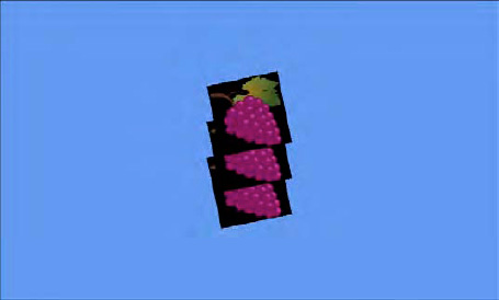
Although the objects appear smaller than they were, the code to render them and the transformations that are applied are completely unchanged; it is just the projection matrix that has caused the change in appearance.
If you want to use a smaller back buffer and take advantage of Windows Phone 7's automatic scaling, this is exceedingly easy using vertex and matrix rendering. Whereas when we were drawing with sprites we had to take into account that the sprites all appeared larger when they were rendered into a smaller back buffer, no such issues occur at all with the new approach.
You can see this for yourself by modifying the buffer size in any of the example projects. Try setting them to half their native size (in a portrait orientation, set the width to 240 pixels and the height to 480). The project will appear with its graphics in exactly the same positions and proportions as they were with the original buffer size. They will, of course, appear a little jagged due to the zooming, but with fast-moving scenes this can be much harder to spot.
Just as we added support for sprite and text rendering into the game framework project, so we will add support for matrix-based rendering. This allows us to continue the simple object-based approach that we have used in the previous chapters and apply it to the new rendering techniques that we have learned in this chapter. All the code in this section can be found inside the GameFrameworkExample project that accompanies this chapter.
Sprites have a fairly limited set of operations that can be performed, so it was easy to wrap up a significant amount of their functionality in the game framework's SpriteObject class. When we render with matrices, there are many more variables to take into account, such as the flexibility of specifying the object's transformation matrix, the different primitives that can be rendered, and the different types of effect (BasicEffect is just one of several effects that are available, as you will see in Chapter 8).
As a result, the game framework's support for matrix rendering is a little less comprehensive than it was for sprite rendering. It provides the features that are most likely to be useful and then allows the individual object classes to use or ignore them as they see fit. They are present in a new class: MatrixObjectBase.
MatrixObjectBase is an abstract class that derives from GameObjectBase (see Figure 6-30). It provides useful properties and functions that we might want to use within our derived game object classes (though in many cases they will be insufficient in isolation and will require additional object-specific properties to be added to the derived classes).

The first content that is present in the class is a range of properties that can be used to control how instances of derived classes will be rendered. The properties contained within the class are as follows:
ObjectTexture: a reference to a texture that will be used when rendering the object (ornullif no texture is required). Defaults tonull.Transformation: a matrix that defines the transformation to use when rendering the object. This will normally be set during the object'sUpdatecall and then used as the world matrix when rendering from theDrawcall.Position,PositionX,PositionY, andPosition Z: a 3D position for the object, represented both as aVector3and a series offloats (though they share the same underlying storage, so modifying the vector will affect the float values, and vice versa). Defaults to (0, 0, 0).Angle,AngleX,AngleY, andAngleZ: three angles that can be used to track rotation of the object around each axis. TheAngleproperty sets or returns the same values as aVector3. Defaults to (0, 0, 0).Scale,ScaleX,ScaleY, andScaleZ: the scaling factors for each axis, available as aVector3or as threefloatvalues. Defaults to (1, 1, 1).ObjectColor: just as with sprites, this allows the color and alpha for the object to be specified. The red, green, and blue components will be passed into the effect object'sDiffuseColorproperty, and its alpha component will be used to determine a value for the effect'sAlphaproperty.
The general approach when rendering objects is to calculate their transformation matrix during the call to each object's Update method, and then use that calculated matrix in its Draw method. Let's take a look at how the transformation is calculated.
There is clearly some overlap between the class's position properties: Transformation is used to store the calculated transformation for the object; whereas the Position, Angle, and Scale properties each make up a part of that transformation. Transformations can be much more complex than simply applying a translation, rotate, and scale matrix, however, because many transformations might need to be applied in an appropriate sequence to achieve the final matrix to use for rendering.
To allow us to achieve a balance between simplicity and flexibility, the class offers a few different approaches for calculating the Transformation matrix.
The first approach is to fully calculate the transformation matrix within the derived class. Essentially this requires the derived Update code to simply place the required matrix into the Transformation property ready to be read back during rendering.
It can do this by multiplying matrices together as we saw in earlier examples in this chapter. It can also take advantage of two simple functions within MatrixObjectBase: SetIdentity and ApplyTransformation.
SetIdentity simply loads the identity matrix into the Transformation property, as shown in Listing 6-30.
Example 6.30. The SetIdentity function implementation
protected void SetIdentity()
    {
        Transformation = Matrix.Identity;
    }
ApplyTransformation takes a transformation matrix as a parameter and multiplies it with the existing Transformation matrix, as shown in Listing 6-31.
Example 6.31. The ApplyTransformation function implementation
protected void ApplyTransformation(Matrix newTransformation)
    {
        Transformation = newTransformation * Transformation;
    }
These are clearly very simple and are almost unnecessary, but they allow simple step-by-step transformations to be applied in an Update function. Listing 6-32 shows an example of such an Update function from a derived class in a game project (it can actually be found in the GameFrameworkExample.TexturedSquareObject class in the example project). This code resets the object transformation to the identity matrix, rotates by the angle stored in the AngleZ property, scales the matrix as per the object's Scale vector, and then translates according to the object's Position. At each stage, the resulting matrix is updated in the Transformation property.
Example 6.32. Applying a series of transformations using the ApplyTransformation function
// Calculate the transformation matrix
        SetIdentity();
        ApplyTransformation(Matrix.CreateRotationZ(AngleZ));
        ApplyTransformation(Matrix.CreateScale(Scale));
        ApplyTransformation(Matrix.CreateTranslation(Position));
Listing 6-33 achieves the exact same result using direct matrix multiplications instead of the SetIdentity and ApplyTransformation functions.
Example 6.33. Applying a series of transformations using direct matrix multiplication
Transformation = Matrix.CreateRotationZ(AngleZ);
        Transformation = Matrix.CreateScale(Scale) * Transformation;
        Transformation = Matrix.CreateTranslation(Position) * Transformation;
Note
If you have experience of programming using OpenGL, the approach that specifies a sequence of transformations shown in Listing 6-32 will probably feel more comfortable because it approximates the approach used by OpenGL to specify its world transformation. Both approaches are functionally identical, though, so use whichever you prefer.
Note that, although these code samples have used some of the standard properties (AngleZ, Scale, and Position), nothing else within the class is taking any notice of them. In this example, they are being used simply as handy places to store information about the location of the object, but they have no further meaning to the class.
The second approach that we can use is to get MatrixObjectBase to apply all the transformation properties automatically. When we do this, it will perform the following steps, in this order:
Translate the object according to its
Positionvector.Rotate the object around the x axis according to its
AngleXvalue.Rotate the object around the y axis according to its
AngleYvalue.Rotate the object around the z axis according to its
AngleZvalue.Scale the object according to its
Scalevector.
The code that performs these transformations is shown in Listing 6-34.
Example 6.34. The MatrixObjectBase.ApplyStandardTransformations function
protected void ApplyStandardTransformations()
    {
        Matrix result;

        // First obtain the object's underlying transformation
        result = Transformation;

        // Apply the object position if any of the coordinates are non-zero
        if (PositionX != 0 || PositionY != 0 || PositionZ != 0)
        {
            // Yes, so apply the position to the current transformation
            result = Matrix.CreateTranslation(Position) * result;
        }

        // Rotate the object if any of the angles are non-zero
        if (AngleX != 0) result = Matrix.CreateRotationX(AngleX) * result;
        if (AngleY != 0) result = Matrix.CreateRotationY(AngleY) * result;
        if (AngleZ != 0) result = Matrix.CreateRotationZ(AngleZ) * result;

        // Scale the object if any of the scale values are set to a value other than 1
        if (ScaleX != 1 || ScaleY != 1 || ScaleZ != 1)
        {
            // Yes, so apply the Scale to the current transformation
            result = Matrix.CreateScale(Scale) * result;
        }

        // Store the final calculated matrix
        Transformation = result;
    }
Sometimes this set of steps will be quite sufficient for a game object, in which case no further processing is required. Listing 6-35 shows how to apply these steps to the object to calculate its transformation matrix. Note that these steps are applied in addition to the existing transformation, so it is important to remember to call SetIdentity first so that they are applied to an identity matrix rather than to any matrix left over from a previous update.
Example 6.35. Applying the standard transformations to an object
// Calculate the transformation matrix
        SetIdentity();
        ApplyStandardTransformations();
Finally, a combination of these two approaches can be used, mixing both custom transformations and the standard transformations together. The transformation matrix can be set both before or after the standard transformations are applied so that customized behavior can be achieved. Listing 6-36 first offsets the object position to the left by one unit and then applies the standard transformations and then translates one unit along the (potentially rotated) y axis.
Example 6.36. Mixing custom and standard transformations
SetIdentity();
        ApplyTransformation(Matrix.CreateTranslation(-1, 0, 0));
        ApplyStandardTransformations();
        ApplyTransformation(Matrix.CreateTranslation(0, 1, 0));
Generally, however, it is best to stick to simple transformations prior to calling ApplyStandardTransformations and no further transformations afterward. Because the standard transformations are not listed step by step within the code as all the other transformations are, it can be confusing to visualize exactly what happens during the ApplyStandardTransformations function call, so mix the two approaches with caution.
With the transformation matrix for the object calculated, the object can now be drawn. As with sprite rendering, this is achieved using a method named Draw, but this time it is passed an Effect object instead of a SpriteBatch. The function is declared as an abstract function, as shown in Listing 6-37, because it has no default implementation, but must be overridden in each derived class.
Example 6.37. The declaration of the MatrixObjectBase.Draw function
public abstract void Draw(GameTime gameTime, Effect effect);
When a class overrides this, it is its responsibility to perform the required steps to draw the object to the screen. Some of this will vary from one class to another, but there are some properties of the effect that can be looked after by MatrixObjectBase. They are handled within a function called PrepareEffect.
The PrepareEffect function ensures that the appropriate texture is set into the effect, that the texturing is enabled or disabled as required, that the DiffuseColor and Alpha properties are set according to the ObjectColor value, and that the calculated Transformation is set. Once all these are in place, the object is ready for rendering. Listing 6-38 shows the implementation of the PrepareEffect function.
Example 6.38. Preparing an effect ready for rendering
protected void PrepareEffect(BasicEffect effect)
    {
        // Do we have a texture? Set the effect as required
        if (ObjectTexture == null)
        {
            // No texture so disable texturing
            effect.TextureEnabled = false;
        }
        else
        {
            // Enable texturing and set the texture into the effect
            effect.TextureEnabled = true;
            if (ObjectTexture != effect.Texture) effect.Texture = ObjectTexture;
        }

        // Set the color and alpha
        effect.DiffuseColor = ObjectColor.ToVector3();
effect.Alpha = (float)ObjectColor.A / 255.0f;
// Apply the transformation matrix
effect.World = Transformation;
// Now the effect is ready for the derived class to actually draw the object
}This can then be easily used within a derived class to set the required effect properties before rendering. Listing 6-39 shows another piece of code from the TexturedSquareObject example class, this time for the Draw function.
Example 6.39. Drawing an object in a derived class
public override void Draw(Microsoft.Xna.Framework.GameTime gameTime, Effect effect)
    {
        // Prepare the effect for drawing
        PrepareEffect(effect);

        // Draw the object
        foreach (EffectPass pass in effect.CurrentTechnique.Passes)
        {
            // Apply the pass
            pass.Apply();
            // Draw the square
            effect.GraphicsDevice.DrawUserPrimitives(PrimitiveType.TriangleStrip,
                                                                        _vertices, 0, 2);
        }
    }
This should all be looking very familiar. If you examine the TexturedSquareObject class as a whole, you will see that it has very little code present, but it still manages to render our textured object to the screen.
There is, of course, no strict requirement to call PrepareEffect, and this work could instead be carried out directly within the derived class if necessary.
The game framework's GameHost class needs a small enhancement to support rendering matrix objects. This takes the form of the DrawObjects function.
DrawObjects performs the same task for matrix-based objects as DrawSprites performs for sprites: it draws all the objects in the game, potentially filtering them by a specified texture for performance reasons. However, we have a slight additional complexity for objects: not all of them actually have a texture. We need to be able to distinguish between drawing all the objects (ignoring textures completely) and drawing the objects for which the texture is null.
We achieve this by creating two public overloads, one that takes a texture as a parameter and draws only objects that use that texture, and one that doesn't take a texture parameter and draws all the objects. Internally, each of these calls into a third (private) overload that expects to be explicitly told whether to filter on textures or not. This allows it to look for objects whose ObjectTexture value is null and draw them alone should this be required.
The code for these functions is shown in Listing 6-40.
Example 6.40. The DrawObjects function overloads in the GameHost class
/// <summary>
    /// Call the Draw method on all matrix objects in the game
    /// </summary>
    public virtual void DrawObjects(GameTime gameTime, Effect effect)
    {
        DrawObjects(gameTime, effect, false, null);
    }

    /// <summary>
    /// Call the Draw method on all matrix objects in the game that use
    /// the specified texture. Pass as null to draw only objects that do
    /// not have a texture specified at all.
    /// </summary>
    public virtual void DrawObjects(GameTime gameTime, Effect effect,
                                                    Texture2D restrictToTexture)
    {
        DrawObjects(gameTime, effect, true, restrictToTexture);
    }

    /// <summary>
    /// Draw the specified objects
    /// </summary>
    private void DrawObjects(GameTime gameTime, Effect effect, bool specifiedTextureOnly,
                                                    Texture2D restrictToTexture)
    {
        GameObjectBase obj;
        int objectCount;

        // Draw each matrix-based object
        objectCount = _objectArray.Length;
        for (int i = 0; i < objectCount; i++)
        {
            obj = _objectArray[i];
            // Is this a matrix object?
            if (obj is MatrixObjectBase)
            {
                // Does this object use the required texture?
                if (specifiedTextureOnly == false ||
                                 ((MatrixObjectBase)obj).ObjectTexture == restrictToTexture)
                {
                    ((MatrixObjectBase)obj).Draw(gameTime, effect);
                }
            }
        }
}The game framework is now all ready to use for rendering our objects, so how is it used in a game project?
This is very easy, as can be seen in the GameFrameworkExampleGame class in the example project. All the class-level variables have been removed except for the BasicEffect variable, and the Initialize function has been reduced in size so that it simply creates and initializes this effect object.
LoadContent now loads its textures into the Textures collection that we've used throughout all the sprite examples. At the end, it calls ResetGame to create the game's objects. ResetGame, shown in Listing 6-41, simply adds some instances of the game project's TexturedSquareObject class to the GameObjects collection.
Example 6.41. Resetting the example project
private void ResetGame()
    {
        // Clear any existing objects
        GameObjects.Clear();

        // Add some new game objects
        GameObjects.Add(new TexturedSquareObject(this, new Vector3(0, 0.6f, 0),
                                                        Textures["Grapes"], 2.0f));
        GameObjects.Add(new TexturedSquareObject(this, new Vector3(0, −0.6f, 0),
                                                        Textures["Strawberry"], 2.0f));
    }
Finally we call UpdateAll from the game's Update function and DrawObjects from the game's Draw function. That's all that is needed.
This chapter has provided a tour through a whole new way of rendering in XNA, using matrix transformations and vertices. If you haven't encountered this approach before, it might seem like a lot of extra work to achieve similar results to those that were already accessible just using sprites.
The real power of this new approach is still ahead of us, however. The examples in this chapter have remained mainly in two dimensions, but matrix transformations and vertex declarations are the gateway into the third dimension, opening up an enormous number of new opportunities for gaming on Windows Phone 7 devices.
All the techniques that you have learned here operate in 3D, too, so, once you feel comfortable with the material that we have covered, prepare yourself for the next chapter, in which you will step into a new world of graphical rendering.