
In this chapter, you will extend your knowledge of XNA and take the features and capabilities of your code up to the next level. When you finish working through this chapter, you will be able to import 3D models from an external modeling application and use a number of additional XNA features to add life to your games.
In Chapter 7, we used two different methods for defining 3D objects in our XNA programs. The first required us to manually define a big array of vertex coordinates. This might be workable for simple objects such as cubes (though it is fairly tedious even for that!), but when we move on to more complex objects such as treasure chests or spaceships, it quickly becomes unrealistic. The second approach used mathematical formulae to create shapes for us (the cylinder from the Lighting example project). This is useful for regular geometric shapes, but once again it is unlikely to be of value for real-world game objects.
The solution is to use a 3D modeling application. Modeling applications are third-party software products that provide a rich (and often rather complex) user interface that is specifically designed to allow 3D models to be constructed.
In addition to creating the geometry, most modeling applications also allow textures to be mapped on to the objects that they build and will provide the resulting texture coordinates. They might also allow vertex normals to be calculated and stored as part of the object.
All this sounds wonderful, but unfortunately there is a bewildering array of formats into which 3D object definitions can be saved, and not all are easy to read.
Many such products can be used to create geometry files that can be used by our XNA games. These range from free products such as the open source Blender (visit www.blender.org for details) to costly commercial applications such as Autodesk's 3ds Max (see www.autodesk.com for more information), and many others in between. Wikipedia has a large list of 3D modeling applications at http://en.wikipedia.org/wiki/3D_computer_graphics_software, where you might be able to find other packages that suit your requirements.
The good news is that there is a modeling application available that is free to download, relatively easy to use, and (with a bit of creative tweaking) can save to a file format that you can easily read. This application is Google's SketchUp.
SketchUp was originally created by a company called @Last Software, with the design goal of creating a 3D modeling application that was just as easy to use as a pen and paper. As such, its user interface was considerably easier to learn than that of many other competing applications.
Some years later, @Last Software enhanced SketchUp so it could create 3D building models for Google Earth. Shortly after this, Google acquired the company and rebranded SketchUp as one of its own applications. You can visit www.sketchup.com to download a copy for yourself.
The new Google SketchUp is available in two different versions: SketchUp and SketchUp Pro. The basic SketchUp version is freely available and contains a huge amount of functionality. The Pro version adds even more features, including support for reading and writing a larger range of 3D file formats.
Unfortunately, the free version doesn't export to a file format that we can easily use within our XNA applications. There is a clever workaround, however, which we will look at shortly.
Even the easiest 3D modeling applications can be complex to use. The challenge of interactively describing a 3D world using 2D input and output devices that we have available to use (the mouse, keyboard, and monitor) is always going to make this requirement difficult to fulfill.
Despite SketchUp's relative ease of use, there is still a lot to learn to become proficient in using it, and a full guide to how to use it is beyond the scope of this book. Don't let this discourage you, though, because SketchUp also has an immense amount of help and guidance available online, including manuals, tutorials, walkthroughs, and video guides. All these can be accessed from the links presented when SketchUp is first launched.
In order to work with imported geometry in this chapter, we will create a simple object in SketchUp that will be subsequently read into an example project by the game engine. The following paragraphs define how a very simple model of a house was created. They are not intended as a step-by-step guide to using SketchUp, but merely provide information about the sequence of operations that could be used to create such a model. The model itself is included with the example projects, so you don't need to re-create it for yourself.
When SketchUp is launched (for reference, this book is written against SketchUp version 8), it prompts us to select a Template. Select one of the two Simple Template options (Meters or Feet and Inches, as you prefer) and then click Start using SketchUp to launch its main user interface. By default, SketchUp adds an image of a person to the empty scene to help put the scene's scale into perspective. The figure can be deleted to make way for the 3D object.
Our object can now be constructed in the empty scene. The first few steps toward this are shown in Figure 8-1. A rectangle is first drawn along the x/z plane to form the base of the house, as shown in Figure 8-1(a). The rectangle is then extruded using the Push/Pull tool to form a box, as shown in Figure 8-1(b). The Line tool is then used to create a line across the center of the top face of the box, as shown in Figure 8-1(c).
Once the top face has been divided in two, the line that was drawn can be moved around, and all the faces connected to it will move accordingly. Moving the line directly upward therefore creates a rudimentary but satisfactory roof shape, as shown in Figure 8-1(d). The basic geometry of the house is complete at this point.
Of course, we will almost certainly want to apply textures to our objects to complement the structure that we have created, and we will do just that now to make the house look more realistic. SketchUp has a set of tools for adding textures to objects, and its online help will provide everything you need to know to get familiar with them.
In Figure 8-1(e), a texture has been applied to the front face of the house. Figure 8-1(f) shows the finished house object, with textures applied to all the faces in the object.

As you might be able to tell, 3D modeling abilities are not among my strengths! Rest assured that XNA can handle much more complex objects than the simple example object presented here.
SketchUp and XNA are both capable of using multiple textures within a single object, so you can import multiple graphic files into the workspace and apply them all as needed. Don't forget, though, that textures can use significant resources in a game, so you should wherever possible try to keep the texture count as low as you can.
One simple approach that reduces the number of textures as far as possible is to place all the graphics for your object into a single texture image, and apply subsections of the image to the model's faces rather than applying the entire image. This is the approach that has been taken with the house shown here: the front, sides, and roof are all contained within a single texture image, as shown in Figure 8-2.

As the graphic shows, the house texture has been divided into three sections: the left third of the texture contains the graphic for the roof, while the remaining area is split into a graphic for the side of the house and another for the front. Putting all the required texture information into a single graphic file in this way simplifies both the design of the object and the rendering. Using a single graphic makes rendering more efficient as the graphics hardware can process the whole object in a single step and it doesn't need to move as many textures around inside the device's memory.
With the object completed, it can be saved to a SketchUp .skp file in case it needs to be retrieved later on.
Unfortunately, the free version of SketchUp has very limited options when it comes to exporting its objects. The two formats natively supported are Collada (.dae) files and Google Earth (.kmz) files.
We could potentially write code to import either of these formats into our XNA games, but a far preferable solution is to find a way to create .x geometry files.
The .x geometry file format was introduced as part of Microsoft's DirectX many years ago and continues to be supported within both DirectX and XNA today. XNA has native support for reading .x files, just as it does for images and sound files, and in fact provides a very easy-to-use programming interface that allows us to save a huge amount of work in terms of reading and processing the geometry file.
So how do we get SketchUp to save its models in .x format? Unfortunately, neither the free nor Pro versions of SketchUp supports this file format.
The good news is that enterprising programmers on the Internet have managed to persuade the free version of SketchUp to export its objects in a variety of other geometry file formats, including .x format. SketchUp provides a programming interface, accessed using the Ruby programming language and able to query all the information about the object that is currently being worked on. A Ruby script has been created by a developer named Fernando Zanini that uses this interface to create .x files from the free version of SketchUp. You can visit http://tinyurl.com/skp2x to download the script or find it in the downloadable content for this chapter in the Resources/3DRadExporter.rbs file. The script works with older versions of SketchUp, too, from version 6 onward.
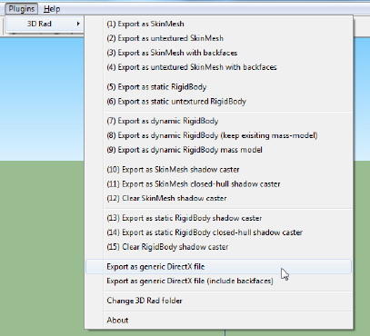
To install the exporter into SketchUp, close the application and then copy 3DRadExported.rbs into SketchUp's PlugIns directory (which can be found by default at C:Program FilesGoogleGoogle SketchUp 8Plugins). Restart SketchUp, and a new 3D Rad menu item should appear under its PlugIns menu, under which is a long list of different export options, as shown in Figure 8-3.
The option that we are primarily interested in is the "Export as generic DirectX file" option. When this option is selected, it will prompt you to select a location and file name for your .x file. You can save it directly into your Content product directory if you want. The exporter will automatically save all the required textures into the same location.
Warning
Don't forget to save your objects into SketchUp's native .skp file format, too. An exported .x file is ideal for loading into your game, but SketchUp can't read data back from it.
Adding the saved object into a project for use within a game is very easy: simply add the .x file to your Content project just as you would for any other content resource. Just add the .x file; there is no need to add any of the textures that it uses. The ImportingGeometry example project has been created using the house model described in the previous section.
Tip
If you want to add the textures into the Content project so that you can see them in Solution Explorer, add them and set their Build Action property to None in the Properties window. This will instruct the compilation process to ignore them, but they can still be manipulated or added to source code control via the Visual Studio IDE.
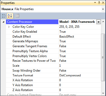
The Properties for the .x model's Content Processor contains several useful options that you might want to configure before using your object, as can be seen in Figure 8-4. When the project is being compiled, Visual Studio converts the .x file into a format that it can more easily use for rendering, and at this stage it can perform some basic transformations on the object geometry.
The first of these properties is Scale. It is very common for objects to be created with wildly different geometry scales, which can end up with objects that are entirely the wrong sizes. This could of course be adjusted by scaling the object within the game, but it adds additional complexity to the matrix transformations, particularly if the object actually needs to change scale while the game is running.
This scaling requirement can be simplified by setting the Scale property, allowing the vertices to be scaled during compilation. The value entered is a numeric value, and as such, only uniform scaling is supported through this property. If you need to scale non-uniformly, you will still need to use a scaling transformation matrix to achieve it.
It is also fairly common when importing an object to find that the coordinate system used for the model is different to that used by XNA, resulting in models that are upside down or otherwise rotated from the way you want them to be. The three Axis Rotation properties can be used to rotate them back to the desired angle. Positive or negative values can be entered, but note that they are entered here in degrees, not radians, as normally used by XNA.
We discussed hidden surface culling in Chapter 7, and also mentioned that some other graphics APIs such as OpenGL display counterclockwise triangles instead of the clockwise triangles used by XNA. If you find that one of your models appears to be rendering inside out, showing you the internal surfaces instead of the external surfaces, you can set the Swap Winding Order property to True. This will instruct XNA to rearrange the vertices of each triangle so that they are in the opposite direction to that defined within the model.
The final properties that we'll touch on here for the moment are the Resize Textures to Power of Two property and the two Color Key properties. They are applied to the textures that are used by the model and are identical in function to the properties of the Texture Content Processor with the same names.
To load the model into your application, simply call the Content.Load method, just as we have for all the other types of data stored within the Content project. The object type to specify for the call is Model. A simple example of loading the house model is shown in Listing 8-1.
Loading a model automatically handles loading all the textures required by the model, so there is no need to load them separately.
How do we render the geometry that we have loaded in our games? The answer, as you might hope, is fairly straightforward, though there are some complexities that we will have to deal with.
The Model object ultimately contains a series of VertexBuffer and IndexBuffer objects, and these are what we will be using to draw the object to the screen. Unlike the simple cube example from the last chapter, however, it is very possible that the model will consist of multiple sets of triangles that all need to be drawn together to form the complete object. For this reason, the model object contains a hierarchy of collections, as shown in Figure 8-5, which must be navigated in order to obtain the vertex data to be drawn.

Contained within the model object is a property named Meshes, which provides a collection of ModelMesh objects. Each ModelMesh represents a group of triangles that are to be rendered in a single position within the object.
The reason for having multiple model mesh objects is that Model objects are able to store geometry that contains complex hierarchies of parts. Imagine, for example, that you wanted to render a model of a helicopter. There are three primary parts to a helicopter model: the main body, the rotor above the body, and the tail rotor. Both of the rotors can move, relative to the helicopter, in order for them to be able to rotate. They are clearly part of the helicopter, but they cannot be rendered purely using the helicopter's transformation matrix.
XNA allows each of these separate pieces of the model, called bones in XNA's terminology, to be individually transformed. This is the reason why the model is stored and rendered in multiple pieces. We won't be going into any further detail about bones and how to use them in this book, but there are plenty of references on the Internet that you should be able to find with a search engine that will give you more information if you want to investigate this subject further.
Contained within the ModelMesh object is yet another collection, this time of ModelMeshPart objects and obtained from the property named MeshParts. Model mesh parts are subsections of the model mesh that collected together contain the geometry of the whole part. The reason for dividing model meshes into separate parts in this way is that each part might have parameters that differ from the other parts, such as the texture. If multiple textures are used within a model, this is the way different textures can be activated and individually rendered.
Within the ModelMeshPart class we finally find where the IndexBuffer and VertexBuffer have been hiding away. Alongside them are several other properties that are essential for us to be able to render the mesh part: VertexOffset is required when the vertex buffer is set into XNA using the SetVertexBuffer function; and NumVertices, StartIndex, and PrimitiveCount are all required by the DrawIndexedPrimitives function.
There are two different methods that we can use to draw the model. The first requires us to loop through each of the mesh parts, telling each one to draw itself using its own Effect object.
These Effect objects are provided by the model so we do not have to create them, but of course they don't know anything about the environment that we have set up. In order for the mesh part to render correctly to the screen, we need to give it the world, view, and projection matrices that it is to use. The easiest way to obtain them is from our own class-level BasicEffect, as defined within our main game class.
A sample piece of code that performs this task is shown in Listing 8-2. In this code, the ObjectModel variable contains the Model being rendered, the effect variable is the class-level BasicEffect, preconfigured with all the matrices required for rendering, and the mesheffect object is used to iterate through each of the Effect objects provided by the model.
Example 8.2. Drawing a model using its component ModelMesh objects
// Build an array of the absolute bone transformation matrices
       Matrix[] boneTransforms = new Matrix[ObjectModel.Bones.Count];
       ObjectModel.CopyAbsoluteBoneTransformsTo(boneTransforms);

       // Loop for each of the meshes within the model
       foreach (ModelMesh mesh in ObjectModel.Meshes)
       {
           // Initialize each of the effects within the mesh
           foreach (BasicEffect mesheffect in mesh.Effects)
           {
               mesheffect.World = boneTransforms[mesh.ParentBone.Index] * effect.World;
               mesheffect.View = effect.View;
               mesheffect.Projection = effect.Projection;
           }
           // Draw the mesh (including all of its meshparts)
           mesh.Draw();
       }
Note
Besides drawing the model, this code also handles the positions of the bones within the model. The call to CopyAbsoluteBoneTransformsTo populates an array with all the final positions for each bone, taking the bone hierarchy into account. These transformations are then combined with the active World matrix to determine the final position for each bone. Because our model does not include bones, the transformations will have no effect at all, but the code is present for compatibility with more complex models.
The code does everything that is needed to get the object appearing on the screen, but it has a drawback: because the Effect objects being used for rendering the model are not the Effect that we have created and configured in our main game class, none of our Effect property values is present in the model's effect objects. As the code in Listing 8-2 shows, the Effect transformation matrices need to be individually copied from our effect into the model's effect objects.
While setting these matrices gets the model appearing in the correct place onscreen, there are lots of other properties that are not being copied here, and will therefore be ignored by the rendered object. These properties include the lighting properties, diffuse and emissive colors, the alpha value, and more.
The alternative therefore is for us to render the model using our own Effect object. This already contains all the properties that we need the model to observe, so we don't need to worry about processing any of them within the rendering code. We can simply loop through the mesh parts, rendering each directly.
There is one critical piece of information that the model's Effect objects contain that our own Effect object does not: the texture to use for each mesh part. The code from Listing 8-2 draws the object fully textured, even though there is no mention of texturing anywhere within the code. We can read the texture out of the model's effects and use it in our own Effect to ensure that the correct texture is applied for each part of the model.
Having done this, the code can then use the information provided by the ModelMeshPart objects to set up the vertex and index buffers, and then draw them. The code to render in this way is shown in Listing 8-3.
Example 8.3. Drawing a model using our Effect object
Matrix initialWorld;
        Matrix[] boneTransforms;

        // Store the initial world matrix
        initialWorld = effect.World;

        // Build an array of the absolute bone transformation matrices
        boneTransforms = new Matrix[ObjectModel.Bones.Count];
        ObjectModel.CopyAbsoluteBoneTransformsTo(boneTransforms);

        // Loop for each mesh
        foreach (ModelMesh mesh in ObjectModel.Meshes)
        {
            // Update the world matrix to account for the position of this bone
            effect.World = boneTransforms[mesh.ParentBone.Index] * effect.World;

            // Loop for each mesh part
            foreach (ModelMeshPart meshpart in mesh.MeshParts)
            {
                // Set the texture for this meshpart
                SetEffectTexture(effect, ((BasicEffect)meshpart.Effect).Texture);
                // Set the vertex and index buffers
                effect.GraphicsDevice.SetVertexBuffer(meshpart.VertexBuffer,
                                                                    meshpart.VertexOffset);
                effect.GraphicsDevice.Indices = meshpart.IndexBuffer;

                // Draw the mesh part
                foreach (EffectPass pass in effect.CurrentTechnique.Passes)
                {
                    // Apply the pass
                    pass.Apply();
// Draw this meshpart
effect.GraphicsDevice.DrawIndexedPrimitives(PrimitiveType.TriangleList,
0, 0, meshpart.NumVertices,
meshpart.StartIndex, meshpart.PrimitiveCount);
}
}
}
// Restore the initial world matrix
effect.World = initialWorld;There are several points of interest in this code. Some of the processing is the same as in Listing 8-2: we retrieve the array of absolute bone transforms and then we loop through the model's Meshes collection. Within each mesh, we no longer have to update the effect properties because we are using our own Effect this time. It is already configured with all the required matrices and its other properties such as lighting, material, and so on. The one thing we do need to do, however, is observe the bone position. We do this by taking a copy of the original World matrix prior to the loop and multiplying this by the bone position for each mesh.
The effect is now ready to render the mesh, so we begin to process each of its parts. The first thing we do for each part is to interrogate its own Effect object to read out the texture that it needs. We pass this, along with our own Effect object, into a procedure called SetEffectTexture. This is a simple function that places the provided Texture2D into the supplied Effect, provided that it is not already present.
With the texture set as needed, the code then sets the mesh part's VertexBuffer and IndexBuffer into the graphics device. This prepares it for indexed rendering as described in the previous chapter. To save XNA from having to process unnecessary vertices, each part provides a VertexOffset. Vertices before this will be ignored by XNA, saving some processing time.
At last the mesh part is ready to render. Just as we always have, we then loop for each EffectPass, rendering the indexed triangle list into each pass. Note that all the details that DrawIndexedPrimitive needs to render are provided by the mesh part, so this is really very straightforward.
Finally, having completed all the loops, the initial World matrix is restored back into our Effect, overwriting any bone transformation that might have been left in place. This stops unexpected transformations from creeping into the rendering process.
Although the code shown in Listing 8-3 isn't especially complicated, it is a little bulky and it would be ideal if we could avoid having to repeat it for each object in our game. Fortunately, the game framework will help us out with this once again, so let's see how we can integrate model rendering into the functionality that we have already added.
Just as we have with the other content resource that we have worked with, we will simplify the task of working with models by allowing them to be loaded into the game framework. These models are added into the GameHost class as a Dictionary of Model objects. All the models that we need can therefore be loaded into the dictionary in the game's LoadContent method, ready to be accessed when they are needed for drawing to the screen.
We could leave it at that as far as the game framework is concerned, but we can make our lives a little easier by adding another abstract base class set up for the purpose of rendering models. This class is named MatrixModelObject and is derived from the MatrixObjectBase class, as shown in Figure 8-6.

Inheriting from MatrixObjectBase means that we immediately pick up all the matrix-based rendering properties, and on top of these we can add some further properties and methods specifically for dealing with models. The class is a concrete (nonabstract) class, however, and can be either directly instantiated and added into the GameObjects collection, or inherited from to create customized classes with additional game-specific functionality.
The derived class's properties are as follows:
ObjectModel: a reference to aModelobject that will be rendered by this class.ObjectTexture: this property is declared by theMatrixObjectBaseclass, but is overridden byMatrixModelObjectso that, if it is queried without a texture ever having been explicitly provided, it attempts to read from the model's textures instead. Once a texture has been set into this property, it will take precedence and be returned in place of the model texture, and will also cause the model to be rendered using the provided texture.
The following methods are present in the class:
DrawModel: this is essentially the same code as shown in Listing 8-3, and will draw the loaded model using the providedEffectobject. It first ensures that anObjectModelhas been provided, and returns without doing anything if no such object is present. Additionally, if a texture has been explicitly provided for the object using theObjectTextureproperty, this will be used instead of the textures from the model, allowing for simple customization of the model textures.Update: the standardUpdatemethod is overloaded so that theEffectproperties can be applied prior to drawing the object. This can be overloaded as normal and the object properties updated as required.Draw: the standardDrawmethod is overloaded and set by default to first callPrepareEffectto load all the object settings and then callDrawModelto render the loaded model. As this will be the exact behavior required for many objects, implementing this in the base class removes the need for the derived class to have to implement its ownDrawoverride.
The new class can be seen working in the ImportingGeometry example project. Once again, the code contained here is very straightforward, taking advantage of the game framework to manage all the more complex aspects of updating and presenting the game. In this project, a derived class named ImportedObject is created simply so that it can change its rotation angles during each call to Update.
Being as focused on content as it is, Google offers a further service alongside the SketchUp application that allows users to upload 3D models that it has created and shares them with the rest of the world.
The service is called 3D Warehouse, and contains tens of thousands of models in .skp format ready for immediate download into SketchUp. Visit http://sketchup.google.com/3dwarehouse to find the front page of the 3D warehouse. A page of search results can be seen in Figure 8-7.

SketchUp isn't designed just for creating game models, however: it can also create extremely intricate 3D scenes and objects that would be far too complex to calculate and display in real time using Windows Phone 7's graphic capabilities. If you decide to search the 3D Warehouse for objects for inclusion within a game, it is important to try to find low polygon objects; that is, objects that have been designed with fast rendering in mind by reducing the number of triangles that are needed.
Objects that use small numbers of textures are preferable, too, and some complex geometry will cause problems for the .x exporter, so you'll need to try the models out in your code and see how they look before you get too attached to them.
The other important aspect of 3D Warehouse is that the objects within it are not in the public domain, but are instead all owned by their authors. If you find a good object, you should contact the author to get permission to use it in your game.
In addition to .x files, XNA is also capable of natively working with Autodesk .fbx files. Other file formats, such as 3D Studio's .3ds format and the popular .obj format, are not supported.
There are several ways that model definitions in other formats might be used within XNA. The first is to import them into SketchUp (or another modeling application that is able to save geometry to .x or .fbx files) and then save them for use within XNA.
A second option is to create your own geometry imported code. If you can read the file format, you can read the file and work through its content, building vertex and index buffers along the way. Depending on the complexity of the file format and the capabilities that you need to support, this process might be a very labor-intensive solution to the problem, however.
Finally, the XNA community has released a number of additional content importers and processors, some of which are targeted at 3D model files. A list of them can be found at http://tinyurl.com/xnamodelfiles, though their integration into Visual Studio is beyond the scope of this book.
If you have ever used a video camera, you know that the most dynamic scenes will have movement from the camera as well as from the actors within the scene. In many games, the ability to manipulate the camera is just as important.
Moving the camera changes the position from which the player looks into the 3D world. The camera is implemented using the View property of the Effect, and we have in fact been using it, albeit without moving it, in all our 3D example projects.
In some ways, having a camera might seem unnecessary. After all, there wouldn't seem to be any visual difference between moving the camera toward an object and moving the object toward the camera. As soon as we start to build up complex multiobject scenes with lights, however, it becomes very much more convenient to be able to calculate the object and light positions without having to worry about moving them all to simulate camera movement.
Let's look at the way in which the position of the camera can be changed in XNA.
To move the camera, we need to figure out exactly how to set the View matrix for the required camera position. Fortunately XNA takes care of this for us and provides a very useful function, CreateLookAt. This builds a view matrix such that the objects subsequently rendered will be positioned as if the camera had moved to the requested location.
The CreateLookAt function requires three pieces of information to be provided, all of which are Vector3 structures. The required values, in the order required by the function, are as follows:
The current position of the camera as a coordinate in the 3D world (the camera position)
A coordinate at which the camera is looking (the target position)
A vector which tells XNA which way is up (the up vector)
The first two of these values are easy to understand. The view will be generated as it would be seen when looking from the camera position directly toward the target position. The specified target position will appear directly in the center of the rendered scene.
The up vector requires a little more explanation. In simple terms, it tells XNA which way is up (toward the top of the screen) relative to the camera position. In most cases, you can provide a vector that simply points along the positive y axis: (0, 1, 0). The up vector does not need to be perpendicular to the camera's direction of view.
There are two situations where a different value for the up vector might need to be used. The first is if we want to be able to roll the camera. Rolling the camera rotates it around its z axis so that its own view of which way is up deviates from the world's view of up (rolling the camera by 180 degrees would result in everything appearing upside down).
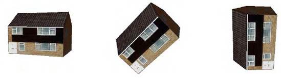
Figure 8-8 shows three views of the house object we imported earlier. In each of these, the house is identically positioned; it is only the camera's up vector that has changed. On the left is the view with the camera's up vector set (0, 1, 0), the default up vector. The middle image shows the view from a camera with an up vector of (0.5, 0.5, 0). The camera has rolled to the right so that its up vector is pointing between up and to the right (similar to tilting your head to the right). As a result, the house appears to have tilted to the left. In the final image, the camera's up vector is (1, 0, 0), so that up is along the positive x axis. The house now appears to have rotated 90 degrees to the left.
Rolling the camera might not be useful in all games, but for some it is extremely handy—any game that simulates the movement of an aircraft or spaceship, for example, will probably want to use it to allow the craft to bank to the sides as it flies.
The second situation where a different up vector is required is when the camera is looking directly along the y axis. If the camera were looking directly upward, we would be telling it that forward and up were both in exactly the same direction. This can't possibly be true, so XNA's transformation matrix results in nothing displaying at all.
In all other cases, XNA is very tolerant of the values provided for the up vector, and will cope fine with unnormalized vectors and vectors that are not perpendicular to the camera viewing angle.
Listing 8-4 shows a simple call to CreateLookAt that sets the camera so that it is located at position (0, 5, 5), is focused on position (0, 0, 0), and has an up vector of (0, 1, 0).
Example 8.4. Creating a view matrix using CreateLookAt
Matrix view = Matrix.CreateLookAt(new Vector3(0, 5, 5),
                                          new Vector3(0, 0, 0),
                                          new Vector3(0, 1, 0));
This code can be made slightly more readable by using some of the static Vector3 properties, as shown in Listing 8-5.
Example 8.5. Creating a view matrix using CreateLookAt and some of the static Vector3 properties
Matrix view = Matrix.CreateLookAt(new Vector3(0, 5, 5), Vector3.Zero, Vector3.Up);
Note
Don't forget the near and far clip planes that have been defined for the viewing frustum. If you move the camera near enough to or far enough from an object that it falls outside these clip planes, it will disappear from view.
It is also possible to set the camera position using matrix manipulation, just as we do for the objects within our scenes. We will look at how to do this in the next section.
Once again, we can simplify manipulation of the camera by integrating it into the game framework. Let's take a look at how it is implemented, and how we can use it in our game projects.
In some ways, it is similar to the general game objects that we are using in our scenes: it has a transformation matrix, has a position, and can be transformed using the matrix transformation functions. For this reason, we will implement a camera class, derived from the MatrixObjectBase and named MatrixCameraObject. The class is concrete (nonabstract) and so can be used directly without needing to inherit a further class from it. The position of the camera class in the inheritance hierarchy can be seen in Figure 8-9.
However, there are some distinct differences between the camera and a standard game object:
There can only be one camera active within the game at any time.
Cameras don't have anything to draw, though they can still update their position like any other normal game object.
The order that the camera position is updated and applied is significant within the 3D scene: if its position is altered halfway through a set of objects, some of the objects will appear relative to the old camera position and others to the new camera position, which could produce very odd-looking results.
We need to know the location at which the camera is looking, and
MatrixObjectBaseclass has no property to define it.

The first of these points is addressed by adding a specific provision for a camera object directly into the GameHost class. Instead of adding the camera object to the GameObjects collection, the camera is set into the GameHost.Camera property. If a camera has been set, it will be processed during each call to Update and Draw. If no camera has been set, no camera-related processing will take place.
Although the second of the points is true (cameras don't have anything to draw), we will still take advantage of both the Update and Draw methods of the MatrixCameraObject class. In the Update method, we can set the camera position, just as we set the position for normal objects. In the Draw method, we will apply the camera position into the Effect object so that it is active for all subsequently rendered objects.
The third point is easily addressed by the game framework. It ensures that the camera is the very last object to be updated (in the GameHost.UpdateAll function) and the first to be drawn (in its DrawObjects function). Updating last ensures that, if the camera position is to be set relative to other objects in the scene (as we will demonstrate shortly), the target objects are always positioned before the camera so that the camera gets up-to-date information. Drawing first ensures that the camera position is active before any of the objects are rendered.
The fourth point is addressed by adding a new Vector3 property to the MatrixCameraObject class named LookAtTarget. This property can be used to specify the location toward which the camera is focused.
The default behavior for the camera class is to position itself at the location specified by its Position matrix, and look toward the location specified in its LookAtTarget vector. If additional positioning logic or a different implementation of the call to Matrix.CreateLookAt is required, the Update and/or Draw methods can be overridden in a derived class as required.
Although we clearly have a good deal of control over the camera simply by setting its Position and LookAtTarget, there is another camera position mechanism that we can take advantage of that will in some situations provide an easier way to put the camera where we want it. This mechanism is to use the matrix transformation approach that we are already using for our game objects.
If we use matrix transformations, we can once again provide a series of operations that the camera will follow through to determine its final position. For example, we might decide to translate the camera to a different position within the scene, rotate the camera's matrix around the y axis by a preset angle, and finally translate a little way along the camera's local z axis. As the rotation angle changes, the camera will orbit around the position defined within the first translation. This is much simpler to calculate than having to use trigonometry to calculate the circular path of the camera if we were simply setting its position vector.
Listing 8-6 shows an example of positioning the camera using this technique, taken from a derived camera class's Update method. It first rotates the camera; then translates along its new z axis and also along its y axis. The end result is that the camera gradually orbits around the scene.
Example 8.6. Positioning a camera using matrix transformations
// Reset the position using the identity matrix
    SetIdentity();
    // Rotate the camera
    ApplyTransformation(Matrix.CreateRotationY(AngleY));
    // Translate the camera away from the origin
    ApplyTransformation(Matrix.CreateTranslation(0, 5, −14));
Compare this approach with that shown in Listing 8-7, which generates exactly the same camera movement, but using trigonometry instead of matrix transformations. Assuming that you are comfortable with using matrix transformations, you will probably find Listing 8-6 much easier to read and understand. The difference between the two would be emphasized further if more complex camera position transformations were required.
Example 8.7. Positioning a camera using the Position vector
// Reset the position using the identity matrix
    SetIdentity();
    // Calculate the camera position
    Position = new Vector3((float)Math.Sin(AngleY) * 14, 5, (float)Math.Cos(AngleY) * 14);
    // Apply the standard transformations to the object
ApplyStandardTransformations();Accompanying this chapter is an example project named CameraMovement, which provides a simple example of using the camera within a game.
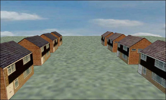
It creates a simple scene consisting of a square of ground on top of which a number of houses have been placed. The camera then rotates around the scene, allowing it to be seen from different angles. All the objects within the scene are completely stationary except for the camera. To allow the scene to better fit within the display, this project has been implemented to use landscape orientations, so you will need to rotate your device or the emulator accordingly. An image from the project can be seen in Figure 8-10.

The project's ResetGame function adds the objects for the ground and the houses into the GameObjects collection and then creates a camera object and sets this into the Camera property.
The camera object is implemented using a custom derived class named CameraObject in order to move the camera around the scene. Within its Update function, you will see two different blocks of code for positioning the camera: one using matrix transformations and the other directly setting the Position property. One of these is initially commented out, but try swapping out the two approaches and experiment with each to see how they work.
You can also try experimenting with the LookAtTarget property so that the camera looks in different directions as it moves around the scene.
One type of camera that is very commonly used within computer games is the chase cam, a camera that follows along behind a key object (usually the player) to provide a first- or third-person view of what the object is able to see within the game world.
We already have many of the pieces in place to implement such a camera in our own games, but with a little enhancement to the game framework's camera class, we can make this absolute simplicity to implement within a game.
This section works through these changes and builds up a scene with a paper plane flying through the scene that we created in the last project. Once we have the plane moving (which will be an interesting task in itself), you will see how to attach the camera so that it automatically chases the plane and configure some different chase cam views.
All the code for this process can be found in the ChaseCam example project.
The paper plane is a very simple 3D model created in SketchUp. It consists of just four triangles arranged to give the basic shape of a paper airplane. The model can be seen in SketchUp in Figure 8-11.

This is positioned so that its center point is approximately on the origin point (0, 0, 0). This positioning will ensure that, when we rotate it, it rotates around its center point.
The object consists only of flat triangles, so in this case we need to ensure that it is exported so that the back faces of each triangle are included, too. Without this, the plane would be visible only from the top side of each triangle, disappearing entirely when viewed from underneath. The .x exporter has an option to export the back faces, too, so this option was used to create the model file.
The SketchUp model file can be found in the Resources folder along with the source code for this chapter.
The plane is then added to the game project as a standard MatrixModelObject-derived class, named PaperPlaneObject. Our goal for the plane is to make it fly smoothly between the houses, however, so we need to add some additional functionality to the class to achieve this.
Several of our previous projects have created objects that move smoothly around the screen in a variety of ways. They have all been based upon velocities that are applied to the objects' positions, however. In this case, we would get a much better flight path for the plane by allowing it to follow a series of movement points that are distributed throughout the 3D scene.
This works well for an example, but is probably not the kind of control mechanism that you would use in a game, which would be more likely to rely on user input to control the player's movement. Following a movement path is nevertheless a useful technique to know and does have a variety of applications in games, from on rails shooters (where the player controls aiming and firing a weapon but has no direct control over his movement) to computer-controlled characters in games.
The first thing that we will do is define a series of points along the movement path that the plane is to follow. They are declared as a static array of Vector3 structures at the beginning of the PaperPlaneObject class. We also store the array size to avoid having to requery it later. The point declaration is shown in Listing 8-8.
Example 8.8. Movement points that define the path along which the plane will travel
// Points on the spline movement path
    static Vector3[] _movementPath =
    {
        new Vector3(-1, 1.5f, −2),
        new Vector3(-1.5f, 2.5f, 2),
        new Vector3(0, 1, 6),
        new Vector3(3, 0.5f, 6),
        new Vector3(4, 1, 2),
        new Vector3(0, 0.4f, 2),
        new Vector3(-4, 0.8f, 1),
        new Vector3(-5, 1.5f, 1),
        new Vector3(-4, 2.5f, −2),
        new Vector3(2, 2.0f, −4),
        new Vector3(4, 1.5f, −7),
        new Vector3(2, 1.0f, −7.2f),
        new Vector3(0, 0.5f, −6),
    };
    static int _movementPathLength = _movementPath.Length;
Tip
These points were determined through a simple process of trial and error. In a game where lots of these points needed to be defined with a reasonable degree of accuracy, it would be well worth creating a simple designer utility to allow them to be positioned on the screen rather than entered by hand.
We could now move the plane between these positions, but the paths between them are undefined. The plane cannot simply jump from one position to another, and even if we calculated a straight line between the points and moved the plane along that line, its movement would look very angular and unnatural.
XNA provides another very useful tool that we can use to solve this problem: a function to calculate splines. A spline is a curved line that passes through a series of points such as those that we have defined. As well as asking for positions directly on the movement path points, we can also ask for points in between, and the spline will calculate a smooth curved transition from one point to the next. This calculated path is ideal for the movement of our plane.
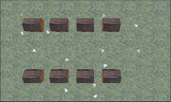
The movement path generated from the spline for the set of movement path positions is shown in Figure 8-12, with a camera looking directly down on the scene. The images of the plane show the positions of the defined movement path points, and the lines between show the approximate spline paths.
There are various spline calculation functions, but the one we will call upon in XNA is called a Catmull-Rom spline (named after its creators, Edwin Catmull and Raphael Rom). It is very useful and simple to use, and ensures that the spline path passes exactly through all the defined positions (which not all splines do).
To generate the spline, the function needs to be passed four consecutive positions on the path along with a weight value between 0 and 1. As the weight increases between these two values, the spline returns positions further along the path.
When a weight value of 0 is provided, the spline will return a position exactly on the second input position. When a weight value of 1 is provided, the spline will return a position exactly on the third input position. All four of the values are used in these calculations, however, to ensure a smooth path both between the second and third positions, and also onward into the next set of movement points.
This can be illustrated using the diagram in Figure 8-13. If the spline is calculated using points 0, 1, 2, and 3, and a weight of 0.0, the resulting position will be exactly on point 1. As the weight increases to 1.0, the spline positions travel along the line between points 1 and 2, reaching point 2 as the weight reaches 1.0. Note that from this set of points the spline positions never return values on the line toward point 0 or point 3, even though they are being passed to the spline function: these outside points are used just to calculate the angle of the curve between the central two points.
Once the weight has reached 1.0, the spline can move on to the next set of points, passing in points 1, 2, 3, and 4. The weight is then once again increased from 0.0 to 1.0, causing the calculated positions to travel along the line between points 2 and 3.
From this set of points, it is impossible to return spline positions between points 0 and 1, or between points 4 and 5 (shown in grey in the diagram) as there are insufficient outer points for these parts of the path to be processed.
By moving point by point through the movement path, a smooth curved line can be produced that passes through all the defined locations. And this all works perfectly well in three-dimensional space, too.

Tip
When defining a path, don't forget that it will take exactly the same amount of time to move between each consecutive pair of points along the path. You should therefore try to ensure that the points are approximately equally spaced. Points that have a larger gap than others will result in faster movement to traverse the increased distance within the fixed time interval, and points that are closer together will result in slower movements because less distance needs to be traveled.
In order to create a closed path, allowing the plane to loop seamlessly back to the beginning of its journey and start again, we need to ensure that the final three points of the spline are identical to the first three points. As the weight of these points reaches 1.0, the spline position will eventually land exactly back at the position of point 1 within the movement path, allowing the whole path to be traced from the beginning once again.
We implement this in the PaperPlaneObject code by storing two class-level variables, an int called _splineIndex, which defines the index of the first of the four points to use for spline calculation; and a float called _splineWeight, which allows us to traverse the path along the spline between the defined points.
In the Update function we add a small amount to the _splineWeight variable. If it reaches or exceeds 1.0, we subtract 1.0 from it and increment the _splineIndex. If _splineIndex passes the end of the movement path point array, it is reset back to the start. These updates move the plane along the spline and reset it back to the start when it reaches the end of its movement path.
With these updates made, we call a function named GetPlanePosition to perform the spline calculation and return the final plane coordinate. The function, which expects the spline index and spline weight values to be passed as parameters, is shown in Listing 8-9.
Example 8.9. Calculating the position on the spline for a given spline index and spline weight
private Vector3 GetPlanePosition(int splineIndex, float splineWeight)
    {
        Vector3 ret;

        // If the weight exceeds 1, reduce by 1 and move to the next index
        if (splineWeight > 1)
        {
            splineWeight -= 1;
splineIndex += 1;
}
// Keep the spline index within the array bounds
splineIndex = splineIndex % _movementPath.Length;
// Calculate the spline position
ret = Vector3.CatmullRom(_movementPath[splineIndex],
_movementPath[(splineIndex + 1) % _movementPathLength],
_movementPath[(splineIndex + 2) % _movementPathLength],
_movementPath[(splineIndex + 3) % _movementPathLength],
splineWeight);
return ret;
}The code first checks that the spline weight is not greater than 1. If it is, it subtracts 1 and shifts on to the next spline index (we'll see the reason for this in a moment). This is followed by a check that loops the spline index if it exceeds the bounds of the _movementPath array items.
The spline position is then calculated simply by passing in the four vertex positions and the spline weight to the Vector3.CatmullRom function. Note, however, that we are using the modulus operator on the spline index values because, if they exceed the array length, they loop back to the beginning. This operation allows us to implement our closed loop (requiring the first three points to be repeated) without actually having to repeat them in the array: they are simply reused from the beginning when the end of the array is reached.
With the ability to calculate the plane position in hand, we can now set the plane's position and smoothly move it along the path. This is a good start, but there is a very obvious visual problem when it is put in motion: the plane is always facing the same direction. It should, of course, always be facing in the direction that it is moving (paper planes as a rule don't fly sideways very well).
Fortunately it is very easy to make the plane look in the direction that it is flying. The first thing we need to do is calculate another position for the plane just a little farther along the path. We do this by calling GetPlanePosition a second time, this time adding 0.1 to the spline weight. This addition is the reason that GetPlanePosition checks whether the weight has exceeded 1.0 because this second call might cause this overflow to occur.
The second call allows us to see where the plane is now and where it will be in a second. The direction of the plane must be from the first of these points to the second because it is its path of movement. We therefore need a way to rotate the plane so that it is facing from the first position toward the second.
This rotation can be achieved using another of the very handy static Matrix functions: CreateWorld. The CreateWorld function creates a world matrix (which is ultimately what we are trying to do in each object's Update method) so that it is positioned at a particular location and facing in a particular direction. This is just what we need: the position is the first spline point we have calculated, and the direction is from there toward the second spline point.
The direction itself is calculated simply by subtracting the current position from the next position. The resulting vector is ready to be passed to CreateWorld.
Only one minor problem remains: the plane is now continuously flying sideways because it has been defined sideways within the SketchUp model. To correct this, we simply rotate it by 90 degrees after the matrix has been calculated.
The full code to calculate the position and orientation of the plane is shown in Listing 8-10.
Example 8.10. Positioning the plane and ensuring that it faces in the direction of flight
// Calculate the current position and store in the Position property
        Vector3 Position = GetPlanePosition(_splineIndex, _splineWeight);

        // Calculate the next position too so we know which way we are moving
        Vector3 nextPosition = GetPlanePosition(_splineIndex, _splineWeight + 0.1f);

        // Find the movement direction
        Vector3 delta = nextPosition - Position;

        // Create the world matrix for the plane
        Transformation = Matrix.CreateWorld(Position, delta, Vector3.Up);
        // The plane needs to be rotated 90 degrees so that it points
        // forward, so apply a rotation
        ApplyTransformation(Matrix.CreateRotationY(MathHelper.ToRadians(-90)));
The end result is that we have a plane that smoothly and realistically flies around the scene between the houses. You can see this in action by running the ChaseCam project—the initial view uses a camera that doesn't chase the plane, but instead slowly circles the scene, allowing the flight path to be easily seen.
Now that we have the plane moving, we are ready to set the camera to follow it.
To allow a game to easily use a chase cam, we will add a new property to the MatrixCameraObject class into which a reference to the target object can be placed. If this property, named ChaseObject, is left at its default (null) value, the camera will act exactly as it did before and just position itself according to its Position and LookAtTarget coordinates. If a game object is provided, however, the behavior of the camera will change so that it follows the object around the scene.
When operating in chase cam mode, the camera has two responsibilities that it must fulfill with each of its updates: it must position itself a little way behind the target object and it must look directly at the target object. Let's see how this can be implemented.
First, the Update code checks to see whether a ChaseObject has been provided. If not, it applies the default object transformation and returns without doing anything more, as shown in Listing 8-11.
Example 8.11. Part of the camera's Update code: behavior for when no ChaseObject has been provided
base.Update(gameTime);

        // Do we have a chase object?
        if (ChaseObject == null)
        {
            // No, so simply apply the identity matrix
            // Calculate and apply the standard camera transformations
            SetIdentity();
            ApplyStandardTransformations();
            return;
        }
If a chase object has been provided, we need to first calculate the camera position. We do this by finding the distance between the current camera position and the object position. Initially the camera position might be nowhere near the object itself, but within a couple of frames it will be positioned behind it ready to chase.
The distance between the camera and the object is found by subtracting the object position from the camera position. The resulting value, named delta, is then normalized to provide a unit-length vector. This vector can then be scaled by the distance at which the camera is to chase in order to locate the camera position.
But what if the camera and the object are in exactly the same place? To deal with this circumstance, we always store the most recent of the distance vectors in a class-level variable, _lastChaseCamDelta, and will reuse this in case of a zero vector. This part of the Update code can be seen in Listing 8-12.
Example 8.12. Part of the camera's Update code: finding the distance between the camera and the target object
// Find the vector between the current position and the chase object position
        delta = Position - ChaseObject.Position;
        // Normalize the delta vector
        delta.Normalize();
        // If the delta is zero (the camera position is already directly on the chase
        // object, which will happen if the object stops moving) retain the last used delta
        if (delta == Vector3.Zero)
        {
            delta = _lastChaseCamDelta;
        }
        else
        {
            // Store the delta for later use
            _lastChaseCamDelta = delta;
        }
Having calculated the direction between the camera and the object, the code is now ready to build the camera's transformation matrix. It begins by translating exactly on top of the object. From here, it translates a little way back from the object so that we can see it from behind. The direction in which this translation is performed is the direction that we have calculated into the delta variable. This direction vector is scaled by the distance we want to keep between the camera and the plane.
The distance is defined in a public property named ChaseDistance. Setting it to positive values will position the camera behind the target object. It can also be set to negative values, however, which will put it in front of the object looking back at it (and generally traveling backward). This camera position can be useful in some situations but does mean that, if the player is in control of the object, he cannot see where he is going!
We also support a special value for ChaseDistance. If it is set to 0, we treat it as being in "first person" mode, which means we are looking directly from the point of view of the object rather than looking over its shoulder. Unfortunately, if we tell XNA to look at the same position as the camera location, it gets confused because it doesn't know which direction to actually point the camera. To work around this problem, we still subtract a small distance from the object position by multiplying delta by 0.01.
We also allow an elevation to be specified for the camera to raise it up a little from the object's location. Typically, you will provide a small elevation so that the camera is looking very slightly downward toward the object. This elevation is set into the ChaseElevation property.
Listing 8-13 shows all the transformations for the camera position.
Example 8.13. Part of the camera's Update code: transforming the camera into position
// Transform the camera position to position it relative to the chase object
        SetIdentity();
        // Translate to the chase object's position
        ApplyTransformation(Matrix.CreateTranslation(ChaseObject.Position));
        // Apply the chase distance. Are we in first- or third-person view?
        if (ChaseDistance != 0)
        {
            // Third person view
            // Translate towards or away from the object based on the ChaseDistance
            ApplyTransformation(Matrix.CreateTranslation(delta * ChaseDistance));
            // Apply the vertical offset
            ApplyTransformation(Matrix.CreateTranslation(0, ChaseElevation, 0));
        }
        else
        {
            // First person view
            // Translate a tiny distance back from the view point
            ApplyTransformation(Matrix.CreateTranslation(delta * 0.01f));
        }
The camera is now positioned relative to the object as defined by the distance and elevation. The final couple of steps are to ensure that the camera is actually looking toward the object and then to update the camera position ready for the next update.
To set the direction that the camera is looking, we simply set the LookAtTarget property to contain the position of the chase object. When the camera's Draw method executes, it will use this value for its CreateLookAt matrix, ensuring that the chase object remains in the center of the screen.
The camera position is then updated by simply setting it to be exactly on top of the chase object. The next time Update is called, assuming that the object has moved, it will once again be able to determine the direction of movement of the object by comparing its new position with the camera position.
These last lines of the Update code are shown in Listing 8-14.
Example 8.14. Part of the camera's Update code: setting the camera's direction and position
// Ensure that we are looking at the chase object
        LookAtTarget = ChaseObject.Position;

        // Set the camera position to exactly match the chase object position
        // so that we can continue to follow it in the next update
Position = ChaseObject.Position;You're ready to fly now, so let's make the last few small changes to the game and see how it looks.
The ResetGame function creates the paper plan object and stores it in a class-level variable called _plane for easy access later on. The camera is created but is initially left without a chase object. As a result, the camera position obeys the transformation that is manually provided rather than following the plane.
This initial configuration appears when the project is run. The houses and plane are visible, but the camera slowly circles the scene. This camera movement path is handled using simple rotation and translation matrices in the game's CameraObject.Update function.
When the player taps the screen, however, we then activate the chase cam. The game class's Update method checks for screen taps, and each time one is found it increments to the next of four camera configurations. The code required to activate the chase cam is shown in Listing 8-15.
Example 8.15. Activating the chase cam
// Follow the plane from behind
                    Camera.ChaseObject = _plane;
                    Camera.ChaseDistance = 1;
                    Camera.ChaseElevation = 0.3f;
This is virtually all that is required to set the camera on its way. The only other change is required to our CameraObject.Update function: if it detects that a chase cam is active (the camera's ChaseObject is not equal to null), it simply calls into the base class and then returns. Any further transformations that the camera code made would either interfere with or entirely replace the camera's own chase cam transformations.
If you run the project and tap the screen once, you will see the chase cam in full effect. An image from the project running in this mode is shown in Figure 8-14.

Tap the screen a second time, and the camera is repositioned in front of the plane, looking back. This is achieved simply by setting the camera's ChaseDistance to a negative value (-1 in this case). Remember that, although the plane knows its flight path and can calculate positions in its future, the camera knows nothing of its future positions, and yet it still positions itself correctly in front of the plane. Being able to set its position without knowledge of the future is important because, if the object were to be player-controlled, it would be impossible to predict its future movements.
Tap the screen a third time to activate the final mode, which displays a first-person camera, which is activated by setting ChaseDistance to 0. There is one further minor change we need to make in order for this to work well: putting the camera directly on the position of the plane results in a clipped image of the front half of the plane being rendered, which looks rather odd—for a first-person camera, we don't want to render the plane at all.
To resolve this first-person rendering problem, we make a small change to the PaperPlaneObject.Draw method. If it detects that it is the camera's ChaseObject and the camera's ChaseDistance is zero, it returns without drawing itself.
Just for fun, we can add some other planes into the scene too. You will find a small block of code inside ResetGame that does this, but it is initially commented out. Uncomment it and you will find a trail of planes happily circling around within the game world.
A useful facility provided by XNA is the ability to add fog to a rendered scene, which provides a simple simulation of real-world fog, making objects that are further away from the camera gradually fade away until they are no longer visible.
Clearly there are limits to the amount of content that Windows Phone 7 devices can render to the screen, and if you have open environments that stretch off into the distance, you need to draw a line at some stage and tell XNA not to draw things that are too far away. This distance limit is generally achieved by setting an appropriate value for the far clip plane when setting up the projection matrix, as was discussed in Chapter 7.
The downside is that, as objects reach the far clip plane, they very visibly vanish. They often leave parts of themselves still visible as they edge past the clip plane, which can result in a very unnatural-looking scene.
You can use fog to help reduce the impact of the vanishing objects by allowing them to fade away before they disappear. This fading results in a much less jarring effect that will often go completely unnoticed by the player.
Fog is also useful as a game feature in its own right. It can make an environment feel much more enclosed and claustrophobic, and can also add atmosphere to a scene, taking away some of the clinical cleanliness that rendered graphics can often suffer from.
Figure 8-15 shows some examples of the scene from the earlier example projects rendered in XNA using fog. The image on the left has fog disabled, although the remaining two images show increasing levels of fog. The distant buildings in the image on the right have completely vanished into the background.

XNA implements fog by using a simple but effective trick. As it calculates the color and lighting for each vertex being rendered, it determines how far away the vertex is from the viewpoint. As the vertex becomes more distant and is therefore affected to a greater degree by the fog, XNA gradually fades the vertex color toward the defined fog color. If the object is sufficiently distant, its vertex colors will be fully set to the defined fog color, causing the object to fade completely away into the background. Just as with other vertex properties, the fog effect interpolates between the vertices of the triangles, causing them all to be appropriately affected by the fog.
Fog is very easy to use, requiring just a small number of parameters to be set. All these parameters are provided by the BasicEffect object, and so we can set them up alongside the rest of the Effect properties when our class-level Effect object is being initialized. The fog properties can, of course, be modified at any stage within the game (even between individual object renders), as required.
There are four properties available to set the behavior and appearance of fog, as follows:
FogEnabled: this booleanvalue switches the fog feature on and off. It defaults tofalse.FogStart: sets the distance (in XNA units, from the camera viewpoint) at which the effects of the fog will begin to be applied. Vertices in front of this distance will not be affected by the fog at all.FogEnd: sets the distance at which the effects of the fog will end. At the end point, the fog is completely opaque, and all vertices at or beyond this distance will be colored entirely in the fog color.FogColor: the color of the fog. Generally when rendering with fog, a solid background color is used, and the fog color is set to match it.
An example of XNA's fog in action can be found in the Fog example project. The fog parameters are set in the FogGame.Initialize function. Feel free to play around with these parameters and experiment with the effect they have on the generated graphics.
A little care is required to produce a good foggy scene. Fog affects only rendered triangles, so the background is not altered by the presence of fog at all. It is therefore important to ensure that the fog color and background color are pretty much the same; otherwise, solid fog-colored structures appear in sharp contrast with the background color.
Using different fog and background colors can be useful, however: if the fog is configured so that the start and end values are both 0 (the whole scene is entirely full of fog), this configuration will produce a silhouette against the scene background in whatever fog color has been defined. The silhouette can be faded back into view by increasing the fog end and start values off into the distance.
It is also important to remember that fog within each triangle is calculated only by interpolation between its vertices. If very large triangles are used (such as the ground in our example), the fog might not always be applied in the way you expect, sometimes resulting in closer objects being affected more by the fog than those further away.
Our 3D worlds are gradually beginning to look and feel more sophisticated, but they currently all suffer from one obvious visible shortcoming: they are all being presented against a blank background.
We created a background image for our sprite projects in Chapter 2 by simply drawing an image with the dimensions of the screen prior to rendering the sprites. This works well in 2D, but in 3D it falls apart: as the camera moves, the background needs to move, too, and we cannot make this happen with a static image.
There are various approaches that we can take to implement a working 3D background, and the one you will look at here is called a skybox. It is called this because it is implemented as a box (a cube) inside which the camera is placed. The camera is centralized within the box, and as its angle changes to look around the scene it also looks around inside the skybox. The result is a realistic-looking background with movement that is consistent with the camera and with the objects within the scene.
An example of a skybox working within our house scene, taken from the SkyBox example project, is shown in Figure 8-16.
Although this example uses a cloudy sky, the skybox technique can be used for all sorts of background effects, from city skylines to interstellar star fields.
The skybox is drawn before any other rendering takes place and switches off writing to the depth buffer. This ensures that the box is always present in the background, and that it has no effect on or interference with the objects drawn in the foreground of the scene. The box is actually fairly small, much smaller than the objects in the main scene in fact, but the rendering order ensures that this is not at all apparent to the end user.
To make the skybox look realistic, we need to move it in a particular way; or rather we need to prevent it from moving from the point of view of the camera. As the camera moves forward through the world, all the objects in the scene should get closer and larger, but the sky remains at a constant distance. This gives the impression that the sky is much larger and farther away than it really is.
We achieve this movement behavior for the sky by always setting the position of the skybox to exactly match that of the camera. As the camera moves around the scene, so too does the skybox. Relative to the camera, therefore, the skybox is not moving at all, resulting in its apparent constant position.
Only the camera's position is copied into the skybox, however: the skybox rotation and up vector are left unchanged. As a result, when the camera looks around in the world, it will look around inside the skybox, too.
An example project using a skybox can be found in the SkyBox example project.
In our example, the skybox is actually implemented as a square tube; it has no top or bottom face. This greatly simplifies the task of creating graphics for the skybox.
The effects of using a tube in this way have been hidden at the top of the skybox by ensuring that the top edge of the sky texture is the same color as the scene's background color, making it hard to see where the skybox ends and the background begins unless it is being directly looked at. At the bottom edge, we ensure that sufficient ground is drawn to hide away the lower edge of the texture. Instead, it simply disappears behind the contents of the scene.
If you are creating a game that needs to be able to look all around the skybox, including up and down, you need to enhance it to create a full cube instead of the tube shape that it is using at present. This is simply a matter of adding two additional faces at the top and bottom of the skybox, both pointing inward.
Generating skybox images can be something of a challenge, depending on what kind of environment you need. One option is to create the background texture yourself. This is how the texture in the example was created: I simply took a photo with a digital camera and then cropped it so that its width was four times its height. You can find the image in the SkyBoxContent project folder.
After cropping, the image just needed a little manual manipulation so that the left and right edges of the image tile properly without leaving a strip where the texture doesn't join together. This tiling effect was achieved using the "Seamless Tiling" effect in Corel's Paint Shop Pro application. If you don't have this or a similar application available, you can copy a strip from one side of the image, flip it around, and then blend it into the opposite side of the image so it is opaque where it touches the edge of the image and then fades to transparent after a short distance across the image.
The skybox image needs to be four times wider than it is tall because it wraps around the four sides of the cube horizontally. Many digital cameras have a panorama feature that allows a number of pictures to be taken and digitally stitched together to create an extra-wide image. This feature can be very handy for creating the required images.
Another option is to use a computer application to create the skybox image. One application that can help with this is Planetside Software's Terragen Classic application (see http://www.planetside.co.uk/content/view/16/28/ for details), which allows a variety of realistic-looking earth scenes to be created, including skies, terrain, and water. These scenes can then be rendered into images with the camera looking north, south, east, and west; and combined together to make an artificially generated skybox image. A good tutorial that explains how this can be achieved can be found at http://www.3drad.com/forum/index.php?topic=3002.0. After the images have been saved, they can be manually stitched together to create the sky scene.
Terragen Classic is free for noncommercial use, but any commercial application of the software will require an inexpensive license to be purchased. Details of how to buy this application are available on the Planetside Software web site.
To make it as easy as possible to use skyboxes, we will integrate a special skybox class into the game framework, allowing us to ensure that it is rendered prior to any other content in the scene.
The skybox is created in a new game framework class: MatrixSkyboxObject. The class is derived from MatrixObjectBase and fits into the inheritance hierarchy as shown in Figure 8-17.

Inside the class, the code creates a vertex buffer for the skybox consisting of the four side faces of a cube (excluding the top and bottom faces), all facing toward their interior. They are configured with texture coordinates that wrap the supplied texture around the inside of the box.
In the skybox class's Update method, the position of the camera is retrieved by reading its Transformation.Translation property and is set as the skybox's own position. Doing this ensures that the skybox always appears the same distance from the camera, regardless of where the camera is positioned within the scene. Reading the position from the camera's transformation matrix ensures that an accurate reading is retrieved regardless of how the camera has been positioned (the camera's Position property might not reflect its final position, depending on how the camera is being transformed). The Update function is shown in Listing 8-16.
Example 8.16. Setting the position of the skybox
public override void Update(GameTime gameTime)
    {
        base.Update(gameTime);

        // Calculate the transformation matrix
        SetIdentity();

        // Observe the camera's position if one is active
        if (Game.Camera != null)
        {
            // Read the camera's calculated position
            ApplyTransformation(
                          Matrix.CreateTranslation(Game.Camera.Transformation.Translation));
        }

        // Now apply the standard transformations
        ApplyStandardTransformations();
    }
When the skybox is drawn, it first switches off any lighting that might be active and then disables the depth buffer. The lighting is important because we don't want light calculations to be applied to the sky—that's not how the real sky works. Disabling the depth buffer ensures that subsequently rendered objects will never appear behind the sky, an effect that would also look somewhat unrealistic.
With the rendering configured, the skybox is drawn. Once the drawing is complete, lighting and the depth buffer are set back to their previous states.
The code for the Draw function is shown in Listing 8-17.
Example 8.17. Drawing the skybox
public override void Draw(Microsoft.Xna.Framework.GameTime gameTime, Effect effect)
    {
        // Prepare the effect for drawing
        PrepareEffect(effect);

        // Disable lighting but remember whether it was switched on...
        bool lightingEnabled = ((BasicEffect)effect).LightingEnabled;
        ((BasicEffect)effect).LightingEnabled = false;
        // Disable the depth buffer
        DepthStencilState depthState = effect.GraphicsDevice.DepthStencilState;
        effect.GraphicsDevice.DepthStencilState = DepthStencilState.None;

        // Set the active vertex buffer
        effect.GraphicsDevice.SetVertexBuffer(_vertexBuffer);

        // Draw the object
        foreach (EffectPass pass in effect.CurrentTechnique.Passes)
        {
            // Apply the pass
            pass.Apply();
            // Draw the sky box
            effect.GraphicsDevice.DrawPrimitives(PrimitiveType.TriangleList,
                                                                  0, _vertices.Length / 3);
        }

        // Re-enable lighting and the depth buffer if required
        if (lightingEnabled) ((BasicEffect)effect).LightingEnabled = true;
        effect.GraphicsDevice.DepthStencilState = depthState;
    }
For the skybox to draw correctly, it needs to be the very first thing that is drawn within the scene. So that we can ensure that this is the case, we treat the skybox as a special game within the GameHost object. In the same way that we added a Camera property to allow the camera to be processed at the appropriate points, so we will add a Skybox property, too. This new property can be set to an instance of the MatrixSkyboxObject class or any class that derives from it.
The GameHost.UpdateAll function updates the skybox object directly after the camera, so that the camera position can be retrieved by the skybox. The GameHost.DrawObjects function draws the skybox after the camera, but before any further objects are rendered. To make sure that the skybox is rendered only once per draw (even if DrawObjects is called multiple times), an internal class variable is used to track the drawing operation, preventing repeat draw operations from taking place.
Overall, this implementation provides a simple but effective skybox that will suffice for many games, particularly those that keep the camera so that it is primarily horizontally oriented. The class can be easily extended to provide full cube geometry if needed.
Another very useful technique that many games will benefit from is the use of particles, which are small, flat, textured rectangles that are drawn into the scene using transparency to create a variety of effects that can add a great deal of atmosphere to your game worlds.
In this section, you will look at how to use particles in a game and then discuss some specific examples.
Particles are added to the game just as any other objects would be, but with the following characteristics:
They frequently use a technique known as billboarding to orient them so that they directly face the camera.
They usually switch off writing to the depth buffer so that they do not occlude one another.
They are often the last things to be rendered into the scene each update. Because they do not update the depth buffer, this rendering order prevents objects that are behind them from appearing in front.
They are nearly always added in groups rather than individually.
You should already be familiar with everything here except for the billboarding technique, so let's look at that in a little more detail.
Billboards are simple quads (flat, square, or rectangular textured objects) rendered in the game world so they face directly toward the camera. As the camera moves around the world, so the billboard objects rotate so that they continue to face directly toward it.
Billboards have a number of potential uses other than for particles, including for rendering lens flares around bright points of light and basic trees rendered using a 2D image such that they always appear face-on to the camera.
For many types of rendered objects, applying a billboard in this way will give the appearance of depth, even though the object is actually completely flat. For example, imagine that you want to render an untextured and unlit spherical object in your game. Such a sphere looks exactly the same from all angles, so if we can simply render a flat drawing of a sphere and keep it angled directly toward the camera, it will be indistinguishable from an actual sphere but with considerably less computational power required to display it.
Billboard quads are very useful for particle systems. If we want to render a firework, we need to ensure that all the points of light that are rendered are actually visible. If we do not use billboarding, the quads that make up the firework could be drawn edge-on to the camera, causing them to become virtually invisible.
Quads rendered as billboards are still placed within the 3D scene, however. They will still retain their position within the game world, will observe the perspective transformation, and will be affected by the z-buffer just as any normal object would.
Figure 8-18 demonstrates the way in which quads are oriented in order for them to appear as billboards. The arrows show the direction in which they are facing. Notice that all the arrows are aligned directly toward the camera. As the camera moves, the quads rotate so that they are always facing toward it.
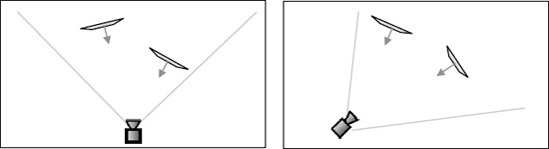
Figure 8.18. A scene viewed from above with billboard quads rotated toward two different camera locations
Getting quads to rotate in this way is actually fairly straightforward. Once again we can call another extremely useful static Matrix function, this time called CreateBillboard. When we call this function, passing it the position of the billboard object and details of the camera position and orientation, it will return a matrix that translates the object to the specified position and rotates the object directly toward the camera.
CreateBillboard expects the following parameters to be passed:
objectPosition: the position of the billboard object.cameraPosition: the position of the camera, which can most easily be obtained by querying theCamera.Transformation.Translationproperty.cameraUpVector: the camera's up vector. Obtained from theCamera.Transformation.Upproperty.cameraForwardVector: a vector indicating the direction in which the camera is looking. Obtained from theCamera.Transformation.Forwardproperty.
With the help of this matrix we ensure that the particles are always aligned to face directly toward the camera. Listing 8-18 shows a section of a particle class's Update code that uses this new function to transform itself ready for display. Notice that it rotates on the z axis after applying the billboard transformation: because the rotation is relative to the object's position, it rotates on the axis that is aligned toward the camera, regardless of how the camera is positioned within the world.
Example 8.18. Billboard transformations for a particle object
// Calculate the transformation matrix
        SetIdentity();
        // Apply the billboard transformation
        ApplyTransformation(Matrix.CreateBillboard(Position,
                                                   Game.Camera.Transformation.Translation,
                                                   Game.Camera.Transformation.Up,
                                                   Game.Camera.Transformation.Forward));
        // Rotate and scale
        ApplyTransformation(Matrix.CreateRotationZ(AngleZ));
ApplyTransformation(Matrix.CreateScale(Scale));The game framework provides some minor changes to more easily support the rendering of particles. It defines a new abstract base class, MatrixParticleObjectBase, from which particle object classes can be derived. The class is abstract, so it cannot be directly instantiated; instead just providing support for derived classes. Its position within the inheritance class hierarchy can be seen in Figure 8-19.

The reason for having this class is that normally particles will be generated after all other objects within the scene, as we have already discussed. Making it possible to identify particle objects through the inheritance hierarchy in this way allows us to ignore them during the normal calls to GameHost.DrawObjects. To allow them to be rendered, the GameHost class provides a new function, DrawParticles, which can be called after all regular object rendering is complete. Just as with DrawObjects, two overloads are provided for DrawParticles: one draws all particles in the whole system, and the other only draws particles using a specified texture. This once again allows you to avoid unnecessary texture changes within the graphics hardware.
The only other functionality added to the particle base class is a public boolean property named IsActive. As particles are frequently created in large volumes and often have short lifespans, they can be put into a dormant state when no longer required rather than being destroyed. This saves unnecessary object instantiation, reducing the frequency of garbage collection. This property can be seen being put to work in the first of the particle example projects, so let's see some particles in action.
The example project FireAndSmoke uses two different particle classes to create a fire within the scene with smoke drifting away from it, as can be seen in Figure 8-20. Much of the code will be very familiar by now so we will just focus on the areas that relate to the particle effect.

The fire is managed through a class called FireParticleObject. Each instance manages a single particle within the fire. The particles are textured using a simple gray blob with an alpha channel applied so that the white areas of the texture are transparent and the darker areas are opaque. The texture is shown in Figure 8-21.

When each particle is created, it generates a position that is randomized within the area of the fire, sets a random vertical velocity, and assigns a random color that is either somewhere between orange and yellow, or between yellow and white. The game creates 75 of these particles, all positioned within the same area.
The particles update themselves by adding their velocity to their PositionY value and then slowly increasing the velocity so that the particles accelerate upward. If they reach a preset height, they reset themselves back to the base of the fire so that the particles are continuously reused to keep the fire burning.
The particles also subtract a small amount from their ObjectColor alpha value, which causes the particles to fade away as they move upward, leaving the fire thinner nearer the top than at the bottom.
Finally, the transformation matrix is calculated, using the code shown back in Listing 8-18.
One further step is performed at the end of the Update function: initializing smoke particles. We'll look at this in more detail in a moment.
When it comes to drawing the particle, the code has a few preparatory steps to perform. First it switches off the lighting because it is unlikely to be useful when the objects are orientated toward the camera (and fire isn't affected by surrounding light, anyway). It then disables writing to the depth buffer and switches on alpha blending. The blend that we use for the fire is the built-in BlendState.Additive blending. As discussed in Chapter 6, this blend mode adds the colors being rendered to those already on the screen, pushing the colors toward white, resulting in a bright glowing effect that is perfect for the fire particles.
The particle is then rendered with a simple call to DrawPrimitives and then the lighting, depth buffer processing, and blend state are all restored to their original states. Restoring the state ensures that the particle rendering leaves the environment in a predictable state for subsequent rendering.
These steps are all that is required to render the fire.
The smoke is implemented by using a second particle class, SmokeParticleObject, which is very similar to the fire particle. Its movement behavior is a little different, but its largest visual difference is that it uses the BlendState.AlphaBlend blending mode instead. It blends the existing screen contentdirectly toward the texture graphics, resulting in a darker effect that works well for smoke.
The smoke particles are managed in a different way from the fire particles. Instead of resetting themselves to their original position after they have expired, they set a property called IsActive to false. Each time the FireParticleObject code wants to add a new smoke particle to the game, it first scans the GameObjects list looking for existing smoke particles that have become inactive. If one is found, it is reset and reactivated, saving the need to create new objects. If no inactive objects are found, a new one is created. This is exactly the same approach that we used for the explosion particles in Cosmic Rocks in Chapter 3.
When the main FireAndSmokeGame class renders the scene's graphics, it draws the smoke particles first and then draws the fire particles. Rendering in this order displays the fire in front of the smoke, which produces a more natural-looking interaction between the two elements of the scene.
The resulting effect might not be photorealistic, but it is pleasing enough and sufficiently convincing for use within games. It is ideal for campfires, flaming torches, or (with a few tweaks to the particle movement) explosions.
Another attractive effect, implemented along very similar lines to the smoke in the previous section, is the vapor or smoke trail. This effect can be applied to all sorts of vehicles, from cars to airplanes, and simulates the exhaust fumes or vapor trails that they leave behind as they travel along.
The effect can be seen in the VaporTrails example project, an image from which is shown in Figure 8-22. This is based on the paper plane scene set up in the ChaseCam project, but with the addition of a simple smoke particle class.
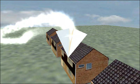
Every three updates, a smoke particle is added to the scene at the end of the PaperPlaneObject.Update function. The function uses exactly the same particle-recycling technique used for the smoke in the FireAndSmoke example, but this time passes the plane's position into the particle's constructor and ResetParticle function. Each smoke particle is therefore positioned directly on top of the plane.
The smoke particles do very little: they gradually increase in size and fade their alpha away toward zero. When the alpha value hits zero, the object is made inactive. Because a new particle is added every third update and they take 255 updates to fade away, this gives approximately 85 smoke particles active in the scene at any time. Try changing the rate at which they are added by altering the modulus operator at the end of the Update code; the trail looks even nicer with more objects, but of course becomes more and more processor-intensive as a result.
The smoke particles in this example are rendered using additive blending rather than alpha blending. Once again this pushes the rendered graphics toward white (particularly as the particles are themselves rendered in white), resulting in a dense smoke trail.
Vapor trails can add a huge amount of energy to a rendered scene, and if processing power permits are well worth considering if you have a use for them.
By now, you are probably getting the hang of particles, so this will be the final example, but it shows another style of particle that once again can enhance the atmosphere of an otherwise simple scene. The FairyDust example project, shown in Figure 8-23, creates a "fairy" particle that moves around the scene, showering multicolored sparkling dust behind it.
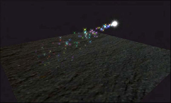
Much of the code in this project is just the same as in the earlier particle projects, so we'll just take a look at the specifics that create this effect. First there is the fairy. If you look carefully at it as it moves around the screen, you will see that it has a shimmering radiance around it formed from beams of light emanating from the center of the object. These moving light beams are created by overlaying two different particle objects in exactly the same location and rotating them in opposite directions. The texture contains the light beams, and as they rotate around one another they produce this shimmering effect. It is a lot less computationally expensive than it looks!
The dust particles are simply star-shaped textures created in random colors, and positioned on top of the fairy when they are initialized. They move in a random direction and gradually apply gravity by increasing the y axis velocity with each update.
Simple, but once again an effective tool for many types of games.
When creating games for Windows or the Xbox 360, XNA offers up an additional graphics programming language called High Level Shader Language (HLSL). This language is targeted very specifically to being able to process instructions relating to the objects drawn upon the screen, and programs written using the language are referred to as shaders.
There are two types of shaders: those that process vertices within rendered objects are known as vertex shaders, and those that work on individual pixels within the objects are pixel shaders. They allow a variety of very flexible effects to be created, including texture distortion, blurring, depth-of-field focus effects, and all kinds of other things.
The bad news is that Windows Phone 7 does not support these programmable shaders, which is something of a limitation compared to the desktop XNA implementation. To go some way to ease the loss of this graphical technique, XNA provides a series of effect objects.
Throughout all the matrix-based rendering, we have been using a class called BasicEffect as the gateway into rendering to the screen. We have defined this in a class-level variable named _effect at the top of each of our game classes. There are several other effects that can be used, however; the complete list is as follows:
BasicEffectis a general-purpose effect with a large number of different configuration options.AlphaTestEffectis an effect that allows flexible depth buffer updates in response to alpha transparency.DualTextureEffectallows two textures to be rendered to geometry at the same time.EnvironmentMapEffectprovides a simple way of simulation reflection of the surrounding environment on to an object.SkinnedEffectis a specialized effect that allows for animation of bones within an XNA model.
This section examines the properties and usage of some of these effects.
Not all effects can use all the features that you have learned about up to this point. In fact, BasicEffect is the only effect that can use many of the features at all. Table 8-1 summarizes the effects and the features that are available for use within each. Those effects flagged as Always are always available and enabled ready for use; those marked Optional are available but must be specifically enabled before they have any effect; those marked Not available cannot be used by that effect at all.
Table 8.1. Effect Types and Capabilities
Feature | Basic | AlphaTest | EnvironmentMap | DualTexture | Skinned |
|---|---|---|---|---|---|
Projection, view, and world matrix | Always | Always | Always | Always | Always |
Diffuse color | Always | Always | Always | Always | Always |
Alpha blending | Always | Always | Always | Always | Always |
Fog | Optional | Optional | Optional | Optional | Optional |
Vertex coloring | Optional | Optional | Not available | Optional | Not available |
Texture mapping | Optional | Always | Always | Always | Always |
Optional | Nor available | Always | Not available | Always | |
Directional lighting | Optional | Not available | Always | Not available | Always |
Specular lighting | Optional | Not available | Not available | Not available | Always |
Per-pixel lighting | Optional | Not available | Not available | Not available | Optional |
Emissive lighting | Optional | Not available | Always | Not available | Always |
Special features | None | Alpha comparison function | Environment map control properties | Second texture property | Properties to set the transforms of the model's bones |
Let's look at these effects in more detail.
The depth buffer is essential for proper rendering in 3D environments, but you can run into problems when you begin rendering transparent objects.
This is because the depth buffer can track only the depth of each pixel on the screen: it doesn't have any concept of transparency. If a semitransparent object is drawn on the screen, and then another opaque object is drawn behind it, how should XNA handle this? Should the object behind be rendered where it overlaps the transparent object (in which case it would incorrectly appear in front of it) or not (in which case the semitransparent object would in effect become opaque)?
The only solution for semitransparent objects is to change the order in which they are rendered to the screen. Objects should be rendered from those in the background first to those in the foreground last. This way, objects will always render on top of other objects that are behind them, allowing the alpha blending to work as required.
There is a special case exception, however, which XNA helps us handle more easily. When we render objects that are partly opaque and partly fully transparent, XNA offers us an alpha test feature that we can use to change the interaction with the depth buffer. Pixels within the texture that pass the alpha test will be rendered both to the screen and the depth buffer as opaque pixels; pixels that fail the alpha test will be considered as transparent, and the screen and depth buffer for that pixel will be left unchanged. Subsequent objects rendered behind the alpha-tested object will therefore show through the transparent areas while still being hidden by the opaque areas.
Just to restate the limitation with the alpha test, the comparison is a binary operation: pixels from the object will either be considered fully transparent or fully opaque. Semitransparent rendering is not supported by this effect.
Figure 8-24 shows an image in which three cubes have been rendered one in front of another using a BasicEffect. The cube is textured with an image that contains a lattice of opaque bars with fully transparent regions in between. To allow the inner faces of the box to be seen, culling has been switched off for this example. The background color is showing through the transparent areas of the texture, as would be expected.

Unwanted interactions between the alpha blending and the depth buffer are visible in two different areas, however. First, the distant cubes are being completely hidden by those in front, even though they are supposed to be transparent. Second, the inner surfaces of each cube are only partly displayed; on the left side of the frontmost box, the inner surface can be seen, but the top and back surfaces are hidden because the front face was drawn before the top and back faces, so the depth buffer thinks they are hidden.
Both of these problems can be cured by switching to use AlphaTestEffect instead of BasicEffect. The same scene is rendered again using AlphaTestEffect in Figure 8-25. You can see that all areas of the boxes that are supposed to be transparent now really are showing through both to their internal surfaces and also to the objects behind.

Switching over to use the AlphaTestEffect is easy, and all the code can be found in the AlphaTest example project. First of all, the _effect variable is changed to be of type AlphaTestEffect instead of BasicEffect, and is instantiated accordingly within the Initialize function.
Next, the effect properties are set. Some of the properties are identical to those used by BasicEffect (including the three matrix properties Projection, View, and World; the VertexColorEnabled property; fog; diffuse color; and alpha). Other properties are forced on by this effect (it always uses texturing and alpha blending, so there is no need to explicitly set them).
As shown in Table 8-1, however, some of the properties of BasicEffect do not exist within this new class. The most awkward of these are probably the lighting properties. Without lighting it can be difficult to mix alpha-tested objects in with other objects that are rendered using BasicEffect with lighting enabled. You will instead need to fall back to specifying vertex colors to provide a rough approximation of lighting.
Finally we get to the good stuff: the new properties offered by this effect. There are two such properties: AlphaFunction and ReferenceAlpha. Between them, these properties provide the mechanism whereby XNA determines whether each rendered pixel should be rendered or not.
Transparency is determined by comparing the alpha value of each pixel in the texture to a reference alpha value that we provide to the effect. The type of comparison performed depends upon the alpha function that we tell the effect to use. If we were to specify an alpha function of GreaterEqual and a reference alpha of 128, all pixels whose alpha value is 128 or more will be rendered as opaque, whereas all those with alpha less than 128 will be rendered transparent.
A number of different alpha functions are available, provided by the CompareFunction enumeration. These functions are Always (the pixel is always rendered as opaque regardless of their alpha values), Never (always rendered transparent, which makes the object entirely invisible), Less, LessEqual, Equal, GreaterEqual, Greater, and NotEqual. All these functions work just as you would expect.
The alpha reference is specified as an integer between 0 (pixels that are fully transparent) and 255 (pixels that are fully opaque).
The code required to instantiate and initialize the AlphaTestEffect is shown in Listing 8-19.
Example 8.19. Creating and initializing an AlphaTestEffect
// Create and initialize the effect
        _effect = new AlphaTestEffect(GraphicsDevice);
        _effect.VertexColorEnabled = false;
        _effect.Projection = projection;
        _effect.View = view;
        _effect.World = Matrix.Identity;
        // Set the effect's alpha test parameters
        _effect.AlphaFunction = CompareFunction.GreaterEqual;
        _effect.ReferenceAlpha = 250;
The game framework also provides a modified version of MatrixObjectBase.PrepareEffect, which expects an AlphaTestEffect as its parameter. It sets only those properties that are relevant for this type of effect.
AlphaTestEffect and BasicEffect objects (and indeed, any of the effect objects) can be used together within the same rendered scene. This is achieved by creating two or more separate effect objects of the required types, and passing the appropriate object into the DrawObjects function from the game class's Draw method.
Another useful rendering feature provided by XNA is the ability to combine two textures together when rendering each triangle.
All our textured objects so far have been given a texture coordinate for each vertex and it has been used by XNA to stretch the texture across the surface of the rendered object. When we use DualTextureEffect, we need to provide two texture coordinates for each vertex, and also two textures to blend together when displaying the object.
This additional texture presents a couple of initial problems to overcome. The first is easy to solve: our game framework objects can store only a reference to a single texture. We'll address this by simply adding a second texture property, ObjectTexture2, to the MatrixObjectBase class.
Then we come to the second problem, whose solution is a little less obvious. The vertex definition structures that we used for textured objects (one of VertexPositionTexture, VertexPositionNormalTexture, or VertexPositionColorTexture) all contain only a single property for specifying a texture. How therefore are we able to tell XNA the vertex coordinates of the second texture?
The answer lies in XNA's capability to work with custom vertex formats. Lots of different pieces of information can be encoded into a vertex format, and we have worked with positions, texture coordinates, colors, and normals throughout this and previous chapters. When working with HLSL, there are lots of other useful things that can be passed in as vertex data, but because Windows Phone 7 has no HLSL support, there are not many situations in which custom vertex formats are useful.
This is one situation where it is useful, however, because it allows us to create a custom vertex format containing a position and two texture coordinates, one for each of the dual textures. The format structure is named VertexPositionDualTexture to match XNA's naming scheme and to make it easily accessible to our games it has been added to the game framework inside the VertexDeclarations.cs source file. The code for the structure is not included here because it doesn't provide anything that we will build on and can simply be treated as a closed source structure, but if you are curious about its implementation, you can take a look in the game framework source code.
How then does XNA combine the two textures together when it is rendering? The calculation is very simple, but deserves a little exploration to understand its implications.
Each final rendered pixel color is calculated using the following formula (treating all red, green, and blue values as floats in the range of 0 to 1):
Rednew
= (Red1 x Red2) x 2
Greennew
= (Green1 x Green2) x 2
Bluenew
= (Blue1 x Blue2) x 2
Alphanew
= (Alpha1 x Alpha2) x 2
In many cases, the easiest way to visualize this calculation in action is to consider the first texture as being the actual texture that is displayed upon the object and the second texture as modulating it by increasing or decreasing its brightness in each of the color components based upon its own color value.
Because each output pixel calculation multiplies the final value by 2, a color component value of 0.5 within one of the textures will have no effect at all on the color from the other texture (it will be multiplied by 0.5, halving it, and then multiplied by 2, restoring it to its original value). On the other hand, a value of 0.0 will remove all color from the other texture, and 1.0 will double the value from the other texture. As always, the colors are clamped, and resulting values above 1.0 will be treated as if they were 1.0.
The DualTexture example project shows two applications of this effect. The one that appears when the project is first launched has its first texture as a piece of rocky ground and its second texture as three white circles on a dark-gray background, as can be seen in Figure 8-26. The code changes the texture coordinates with each update, causing the two textures to gradually move across the face of the rendered square.
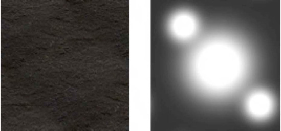
The circles form an effective-looking spotlight effect on the ground. Their background color is darker than mid-gray, causing them to darken the ground texture, but the circles themselves are obviously very bright, illuminating the texture. The resulting image is shown in Figure 8-27—once again, it looks better in motion than in a still image.
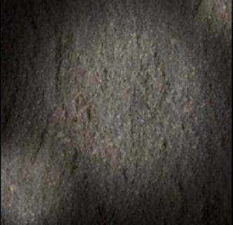
The example project contains a second, much more colorful example, too. Edit the code and swap over the commenting of the two calls to GameObjects.Add in the DualTextureGame.ResetGame function so that the two moiré textures are passed instead of the ground and lights textures. These two new textures contain a series of concentric circles, as shown in Figure 8-28. Both textures contain the same pattern but in different colors.

These textures are combined using exactly the same code as before, but this time the concentrated patterns of bright and dark color interfere with each other to create a fantastic-looking interference pattern, which can be seen in Figure 8-29. And yes, this one looks better in motion, too!
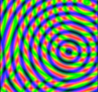
Using DualTextureEffect is very simple. Create an instance of it in your game class and configure its properties as necessary. Once again it has a limited set of properties compared to BasicEffect, with no support for lighting.
When setting up your vertex buffers, declare them to be of type VertexPositionDualTexture, and set their texture coordinates using the two properties TexCoord0 and TexCoord1. The two textures are provided to the game objects in their ObjectTexture and ObjectTexture2 properties.
The next of the XNA effects is the EnvironmentMapEffect. We already saw some fairly shiny objects when we were experimenting with specular lighting in the previous chapter, but environment mapping allows us to take shiny surfaces to the next level.
Environment mapping is a technique that simulates the reflections of an object's surrounding onto the object itself. If your game is set in a forest, for example, you might want to reflect a forest image onto some of the objects in your game. Objects that use environment mapping in this way look like they are highly polished (which suits some objects more than others; for example, objects made of metal, glass, or polished wood will benefit from environment mapping, but objects with matte surfaces such as brick or plastic will probably look very strange).
It usually isn't important that the reflections being used for the environment map actually be accurate; as long as they fit in with the scene, users will be fooled into thinking they are seeing the real environment rather than a static image. Showing a reflection of a forest when the player is exploring a cave will, of course, be a little more jarring, so make sure the scene and the environment map match up.
In addition to allowing objects to reflect the environment, XNA's environment mapping also allows objects to have their own static textures, just like those used by the other effects. The effect of the object's own texture and its reflected environment leads to a very convincing illusion of reflectivity.
There are some minor challenges involved in setting up an environment map, but fortunately once you know how to do it, the process is very easy. And you will know exactly how to do it very soon! The code that we will look at in this section can be found in the EnvironmentMap project, and some images from it can be seen in Figure 8-30 (and yes, once again, this example also looks better in motion).
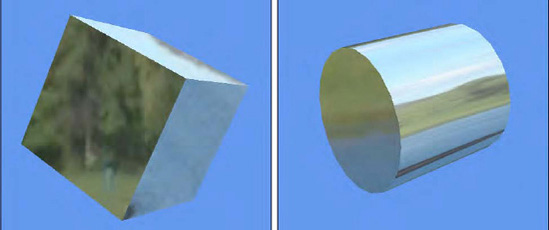
The EnvironmentMapEffect object is in many ways very similar to BasicEffect because it offers most of the same lighting properties and other effects. The only features that are absent, as compared with BasicEffect, are specular lighting and vertex coloring.
The effect needs a texture so that it can texture the object, and the MatrixObjectBase.PrepareEffect function will once again take care of providing this texture from each object's ObjectTexture property. A valid texture is a requirement of the EnvironmentMapEffect and setting its texture to null will result in a black silhouette of the object appearing. It is possible to render without applying a texture to the object, however, and we will look at how this can be achieved in a moment.
The reflection functionality offered by this new effect is implemented by a new feature called an environment map. This map contains the texture that will be used for reflections on the rendered objects. However, we have a problem with setting the effect's EnvironmentMap property: its type is TextureCube rather than Texture2D, and this is a new type of object that we have not encountered before. How can we generate a TextureCube object?
A texture cube is similar in function to the skybox that we looked at earlier on: it is a set of six textures that can be applied to the front, back, left, right, top, and bottom faces of a cube such that when viewed from the inside they form a consistent seamless environment in all directions. XNA provides no built-in way to create texture cubes from an image, but one of the XNA sample projects that Microsoft released separately provides everything that is needed to very easily create a texture cube.
The sample project can be found at http://create.msdn.com/en-US/education/catalog/sample/custom_model_effect, and the relevant project from it is also included in this chapter's source code in the CustomModelEffectPipeline folder. It has been copied directly from the sample project without any modification.
The project contains an XNA game library, but it is one that we will use only as part of the compilation process; it doesn't get distributed along with your finished game. Instead it adds a custom content processor that the Content project can use to transform a simple PNG or JPG image into a texture cube.
To use the content processor, add the CustomModelEffectPipeline project to your solution. Then open the References branch of the Content project within Solution Explorer, right-click Add Reference, and select the CustomModelEffectPipeline item from the Add Reference window's Projects tab. When this is done, the project will appear as a reference alongside the other content processors provided by XNA, as shown in Figure 8-31.
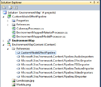
Now that the Content project is aware of the custom content processor, it can be used to transform a graphic file into a TextureCube instead of a Texture2D object. To do this, add the image that you want to use for the environment map (Landscape.jpg in the example project) and edit its properties. The initial setting for the Content Processor property is Texture - XNA Framework. If you open the drop-down list for this property, you will find that some new processors have appeared, all of which are provided by the CustomModelEffectPipeline code. Select CubemapProcessor as the processor to use, as shown in Figure 8-32. When the project is compiled, this texture will now be created as a texture cube.
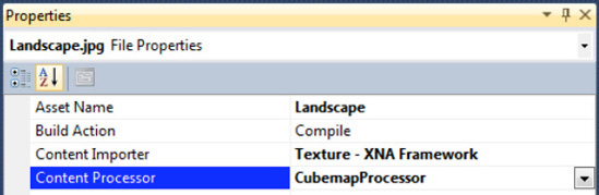
Note
There is no need to worry about making seamless wrapping graphic files before providing them to the CubemapProcessor: it will cleverly distort the image in a way that automatically wraps the image seamlessly around all the faces of the texture cube.
This configuration change is everything we need to prepare the TextureCube; now we simply need to activate it within the game. After instantiating and initializing the EnvironmentMapEffect, the TextureCube can be read from the Content object and set into the EnvironmentMap property. The code to do this, taken from the example project's LoadContent function, is shown in Listing 8-20.
Example 8.20. Loading a TextureCube into the EnvironmentMapEffect object
// Load the environment cube map
        _effect.EnvironmentMap = Content.Load<TextureCube>("Landscape");
Note
We could easily add a new collection of TextureCube objects into the game framework, but because it is likely that only one will be used at a time, it is more straightforward to simply load it directly into the effect. Feel free to extend the game framework yourself to support a collection of texture cubes if you would find it useful.
Once the effect's environment map is set, all that is left is to simply render some objects. It is important that the objects have vertex normals configured correctly because the effect uses them (along with the vertex position) to determine which part of the environment map should reflect on each part of the object, but no further object configuration is required.
Tip
Don't forget to configure the scene's lighting. Without it your objects will be entirely unlit but will still reflect their environment, which is probably not what you are expecting to see.
Several additional effect properties are available to control the way in which the environment mapping is applied to your rendered objects.
First is the EnvironmentMapAmount property, which controls the strength of the blending effect between the environment texture and the object's own texture, in the range of 0 to 1. When set to 1 (its default value), the environment map will completely replace the object's texture; when set to 0, the environment map will be completely switched off. Values between will provide varying levels of subtlety to the strength of reflections.
Next is the EnvironmentMapSpecular property. If you encode additional data into your image's alpha channel, this property can be used to implement a cheap simulation of specular lighting on your objects. This effect works better when the object is highly curvy because large flat surfaces tend to break the illusion of the specular lighting. The EnvironmentMapSpecular property allows a color to be specified with which the alpha channel data will be tinted. It defaults to black, which disables this effect.
Tip
Don't forget that JPG graphic files can't store alpha channel information, so this feature can be used only with PNG image files. Due to the way that the cubemap processor transforms the image into its texture cube, the resulting image sizes will not be hugely different because the images are recompressed in the same way regardless of the source image format.
The final property is the FresnelFactor. Another float property that ranges from 0 to 1, this property controls how the reflectivity of an object changes as relative to the viewing angle. With a FresnelFactor value of 1 (the default), object surfaces will stop reflecting the environment entirely when they are facing directly toward the camera, though they will increasingly reflect as they rotate away. A FresnelFactor of 0 disables this effect entirely so that the object reflectivity takes no account of the viewing angle. Values between make this effect more or less pronounced.
It is very useful to be able to experiment with these properties when setting up your environment-mapped objects. Highly reflective objects look very pretty, but are not necessarily all that realistic. Great results can be had from applying subtle environment mapping to your objects that the user is perhaps only subconsciously aware of.
To allow each of the objects within our games to have independent control over their environmental mapping settings, corresponding properties named EnvironmentMapAmount, EnvironmentMapSpecular, and FresnelFactor have been added to MatrixObjectBase in the game framework. They default to the values 1, Black, and 1, respectively, to match the defaults provided by XNA.
It will sometimes be useful to draw objects that are entirely reflective and that have no texture of their own visible at all. This can be achieved by setting the EnvironmentMapAmount to 1, but it is still necessary to have a texture applied to the object itself, or else the object will appear completely black.
There are two things we can do to address this problem. The first is to create a 1-x-1-pixel white dummy texture and apply it to the objects in question. They will therefore be textured (in white), so the environment mapping will apply as required.
The only real downside is that the dummy texture needs to be loaded into the graphics hardware, replacing any other texture that might already be there. That other texture might then need to be subsequently reloaded, causing a performance hit.
The other alternative is to leave whatever texture is already in the graphics hardware active so that it will apply to the object being rendered. This texture might, of course, be entirely unsuitable for the new object, which probably hasn't been set up with any texture coordinates at all. To prevent it from causing unpredictable results, we can configure the environment mapping settings for the object to have an EnvironmentMapAmount of 1 and a FresnelFactor of 0. This will cause the environment map to completely overpower the object texture so that it has no visible effect whatsoever.
The game framework will set the environment map properties in this way if it detects that no texture has been set for the object being rendered. It is essential that there are other objects within the scene that do activate a texture within the EnvironmentMapEffect, however, so that a texture is set prior to the object being rendered. If this is not the case, a dummy texture will need to be applied as described previously.
The final effect is the SkinnedEffect. This effect doesn't provide graphical effects in the way that the other effects have, but rather allows models that contain multiple bones to be controlled such that each bone can be moved around its joints to position complex models into different poses.
Creating models such as these is beyond the scope of this book, so we will not be going into any further detail about this particular effect. If you want to learn more and see the effect in action, take a look at the XNA Reach Graphics Demo, which can be found by pointing your web browser at http://create.msdn.com/en-US/education/catalog/sample/reach_graphics_demo and downloading the source code at the bottom of the page.
We have nearly finished our journey through XNA's matrix-based rendering now, but there is one final topic to cover: mixing rendering from sprites and from matrix-based graphics together at the same time.
There are obvious uses to rendering sprites and matrices together: 3D games will frequently need to display text, for example, and it is likely that 2D status overlays (energy bars, number of lives left, and so on) might be useful, too. XNA allows us to achieve this by rendering sprites and 3D objects together into the same scene.
Simply draw the 3D objects first and then draw the sprites afterward. Both will render exactly as you would expect, with the sprites appearing on top of any 3D objects that have already been rendered onscreen.
XNA's sprite renderer does, however, make some changes to the state of the rendering engine, and they will most likely need some minor additional changes to your code to compensate. When XNA begins rendering sprites, it reconfigures the environment as follows:
GraphicsDevice.BlendStateis set toBlendState.AlphaBlend. You will probably want to set it back toBlendState.Opaque, or whatever other blend state you require.GraphicsDevice.DepthStencilStateis set toDepthStencilState.None, disabling the depth buffer (remember that sprites handle depth purely through theLayerDepthvalue on each rendered sprite). You will almost certainly need to set this back toDepthStencilState.Default.GraphicsDevice.RasterizerStateis set toRasterizerState.CullCounterClockwise. This is its default value, anyway, so might not have any impact on your code.GraphicsDevice.SamplerState[0]is set toSamplerState.LinearClamp. This will prevent tiling of textures on your 3D objects, so you might want to revert this back toSamplerState.LinearWrap.
To simplify the management of these render states, two new functions have been added to the game framework's GameHost class: StoreStateBeforeSprites and RestoreStateAfterSprites. The StoreStateBeforeSprites function reads the current value for all four of these state properties and stores them away into private class variables within GameHost. This function should be called prior to calling the SpriteBatch.Begin method. The RestoreStateAfterSprites function retrieves these stored values and makes them current once again, and should be called after SpriteBatch.End. Storing and restoring the state in this way hides the state changes that the SpriteBatch makes, allowing the rest of the rendering code to continue unaffected.
Listing 8-21 shows the source code for these two functions.
Example 8.21. Storing and restoring the graphics device state for before and after rendering sprites
protected void StoreStateBeforeSprites()
    {
        _preSpriteBlendState = GraphicsDevice.BlendState;
        _preSpriteDepthStencilState = GraphicsDevice.DepthStencilState;
        _preSpriteRasterizerState = GraphicsDevice.RasterizerState;
        _preSpriteSamplerState = GraphicsDevice.SamplerStates[0];
    }

    protected void RestoreStateAfterSprites()
    {
        GraphicsDevice.BlendState = _preSpriteBlendState;
        GraphicsDevice.DepthStencilState = _preSpriteDepthStencilState;
        GraphicsDevice.RasterizerState = _preSpriteRasterizerState;
        GraphicsDevice.SamplerStates[0] = _preSpriteSamplerState;
    }
Listing 8-22 shows a Draw function that renders both 3D objects and sprites together, using the StoreStateBeforeSprites and RestoreStateAfterSprites functions to ensure that the rendering state is not modified by the sprites.
Example 8.22. Drawing 3D objects and sprites together, storing and restoring the rendering state
protected override void Draw(GameTime gameTime)
    {
        GraphicsDevice.Clear(Color.CornflowerBlue);

        // Draw all 3D objects
        DrawObjects(gameTime, _effect);
// Draw all sprites and text...
// First store the graphics device state
StoreStateBeforeSprites();
// Draw the sprites
_spriteBatch.Begin(SpriteSortMode.BackToFront, BlendState.AlphaBlend);
DrawSprites(gameTime, _spriteBatch);
DrawText(gameTime, _spriteBatch);
_spriteBatch.End();
// Now restore the graphics device state
RestoreStateAfterSprites();
base.Draw(gameTime);
}An example of using this technique can be found in the SpritesAndSolids example, from which Listing 8-22 was copied and from which an image is shown in Figure 8-33. You will see that it displays solid 3D objects, sprites, and text all on the screen at once. The two cubes intersect and can be clearly seen to still be observing and updating the depth buffer despite the SpriteBatch having disabled it. The semitransparent balloons show through to the 3D rendered content behind them.

Because the sprites disable the depth buffer, they have no impact at all on any subsequent 3D objects that are rendered. It is, therefore, very easy to display sprites behind 3D objects, too: just render them first and the 3D objects second. If you want to create scenes that have some sprites behind the 3D objects and others in front, draw the background sprites first, then the 3D objects, and then the foreground sprites. Listing 8-23 shows a simple example of how this can be achieved.
Example 8.23. Drawing background and foreground sprites
// Draw background sprites
        StoreStateBeforeSprites();
        _spriteBatch.Begin(SpriteSortMode.BackToFront, BlendState.AlphaBlend);
DrawSprites(gameTime, _spriteBatch, Textures["BackgroundTexture"]);
_spriteBatch.End();
RestoreStateAfterSprites();
// Draw all 3D objects
DrawObjects(gameTime, _effect);
// Draw foreground sprites
StoreStateBeforeSprites();
_spriteBatch.Begin(SpriteSortMode.BackToFront, BlendState.AlphaBlend);
DrawSprites(gameTime, _spriteBatch, Textures["ForegroundTexture"]);
_spriteBatch.End();
RestoreStateAfterSprites();The gaming opportunities with 3D graphics are immense, and I hope that you now feel armed and prepared to go and conquer them. It is a complex environment to work with, and sometimes things won't work or look exactly the way you expect them to. Experimentation is key, however, so use the knowledge that you have gained to create test projects and try things out. With a little practice, you should find that things start to feel much more natural and manageable.
While we've covered a lot of XNA's functionality, it is a very rich and flexible environment and there's a great deal more that you can learn about it if you want to extend your knowledge further. The MSDN App Hub web site at http://create.msdn.com is probably the best learning resource.
The Education and Resources sections have enormous volumes of information that you can use to further your abilities, and the Community section has a highly active set of forums into which you can post for help if you need it. The community is always grateful for any help that you can provide, so please help to share your knowledge to others if you can!
The next chapter steps back from 3D rendering and looks at some useful functions that you can add to your games to enhance their features.