
For the next few chapters, we will look at the XNA environment and learn all we need to know to use it for displaying graphics, reading user input, and playing music and sound effects. XNA is in some ways a more straightforward approach to games programming than Silverlight, offering a very draw-things-to-the-screen approach to its graphics rendering, rather than Silverlight's somewhat more complex control hierarchies. Its entire focus is on games and game programming, whereas Silverlight is a general-purpose graphical interface rather than a gaming engine. XNA also takes full advantage of the graphical hardware acceleration built into the device, whereas Silverlight performs a lot more of its processing using the CPU instead.
In this chapter, we will focus on some of the fundamental mechanics of XNA and drawing graphics in 2D. These are important even if you wish to focus on 3D games because the underlying program structure is identical. Even in 3D applications, you are likely to want to use some 2D graphics as well to present status information or text to the user, so it is important to have a good understanding of XNA's capabilities in this area. We'll look at how these principles begin to build into a proper game in Chapter 3.
In the world of desktop development, DirectX has for many years been the Microsoft graphical API. It is very powerful with excellent support for all sorts of 2D and 3D graphical effects, and when paired with a capable graphics card can produce breathtaking scenes and animations.
For many generations of DirectX, the API was really accessible only by developing in C or C++. All the library information was made available to these languages, and, although it was theoretically possible to access them from Visual Basic 6, and later from the .NET languages, it was a significant amount of work to actually do so.
With the introduction of DirectX 9 in 2002, Microsoft provided a set of .NET libraries known as Managed DirectX (MDX). This finally gave a proper supported interface for .NET developers to use to access the DirectX features.
Before MDX was established, however, Microsoft changed direction and released a replacement set of technologies called XNA (it officially stands for XNA's Not Acronymed in case you were curious—I expect you wish you hadn't asked now!). XNA also offers a fully managed interface, available from any .NET language, and wraps around DirectX functionality. It also allows cross-platform development, initially supporting Windows and the Xbox 360, adding the Zune portable media player, and now finally providing support for Windows Phone 7, too.
For the most part, the functionality available on Windows Phone 7 is the same as for the Windows and Xbox versions. The only significant feature missing is the ability to program shaders. Shaders are a cut-down programming language that allow for custom processing of graphics as they are being calculated and displayed to the screen, and are typically used for effects such as blurring, lighting, reflections, and so on. Despite the lack of programmable shader support in Windows Phone, a set of predefined shader functions are provided and can be used in XNA games, as we will see later on.
The version of XNA used for Windows Phone 7 development is version 4.0, which is being released for Windows and Xbox at the same time as it is for the phone. XNA 4.0 contains changes to some of its libraries that are incompatible with earlier versions. It is important to bear this in mind when asking or searching for help on the Internet to avoid confusion if you should encounter one of these changes.
That's enough of the history lesson; let's move on and get some coding underway.
Our first project will be very basic: simply displaying a moving graphic on the screen. We can use this as an opportunity to see some of the basic functions of an XNA game and to look at the development environment that XNA games all use.
In the following sections, we will build up this first XNA project. If you wish to look at the finished source code, you will find it in Chapter 2's FirstXNAProject folder in the download accompanying this book.
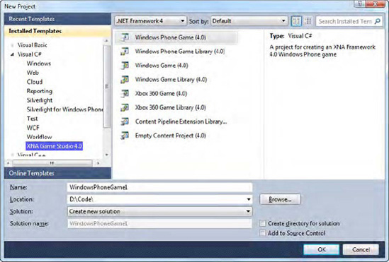
To get things started, fire up Visual Studio 2010 and select to create a new XNA Game Studio 4 Windows Phone Game project, as shown in Figure 2-1. Give it a name and optionally uncheck the "Create directory for solution" box (Visual Studio creates a lot of nested directories if this is checked); then click OK to create the project.
The project will be created by Visual Studio and opened in the IDE. The initial window that you will be presented with after this is completed is the code window for the Game1.cs file, which, as you will see, already contains a fair amount of code.
You can, in fact, run the project without doing anything more. The emulator will launch, and after its initialization is complete (you may need to be a little patient), the game will start. It doesn't do very much; it just displays an empty blue screen.
The blue screen is actually of some use, though: seeing the screen turn blue tells you that the program actually is running and is managing to render to the screen. Having a default that isn't black lets you know that the project is operating normally and hasn't just crashed with a blank screen.
Now let's put something on the screen other than just a solid color.
Click the Stop Debugging button in Visual Studio to return your project to edit mode. Right-click the Content project node; select Add and then Existing Item, as shown in Figure 2-2.

In the file browser window that appears, choose a graphic file that you wish to display on the screen. Try to pick something that will actually fit on the screen; if you want to use the smiley face graphic that is shown in the following example, you can find it in the Content folder for the FirstXNAProject example in the source code that accompanies this book.
Tip
Visual Studio will automatically copy any content files that you select into the Content project's directory, if they are not already present there. This means that there is no need to manually copy files into this folder before selecting them, nor is there a need to keep the files in their selected locations on your hard drive after they have been added.
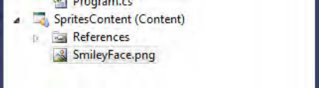
Once this has been done, the graphic file will appear within the Content project inside Solution Explorer, as shown in Figure 2-3.
With our graphic in place, we can now amend the code to display it on the screen. This is very simple and consists only of modifications to Game1.cs, so ensure that it is open in the code editor.
First of all, we need to add a class-level object into which our graphic image will be stored. The object type for this is Texture2D, and so we declare it, as shown in Listing 2-1, just below the existing spriteBatch declaration.
Note
As a naming convention in this book, private class fields will be prefixed with an underscore. All fields will be defined as being private, with internal or public properties added to access them if required.
The next step required is to load the graphic into the variable that we have created. This is performed in the class's LoadContent procedure, which you'll find about halfway through the source code. In addition to the existing code, we load the texture by calling the Content.Load function, as shown in Listing 2-2.
Example 2.2. Loading the graphic file into the Texture2D object
/// <summary>
    /// LoadContent will be called once per game and is the place to load
    /// all of your content.
    /// </summary>
    protected override void LoadContent()
    {
        // Create a new SpriteBatch, which can be used to draw textures.
        spriteBatch = new SpriteBatch(GraphicsDevice);

        // Use this.Content to load your game content here
        _smileyTexture = Content.Load<Texture2D>("SmileyFace");
    }
The Content.Load function uses .NET's generics feature to allow us to specify its return type. In this case, we want it to return a Texture2D object, and so we specify this type in the angle brackets in the function call. We then pass the parameter SmileyFace. Note that this doesn't exactly match the file name that we added to the Content project because the file extension is missing. The reason for this is that the Content project automatically assigns an asset name to each file that is added, defaulting this to the file name without its extension. You can see this by selecting the graphic file in the Content project and examining its properties, as shown in Figure 2-4. The Asset Name property is editable and can be modified if you wish.

The project is now loading the graphic, and so the final step is to display it on the screen. This is achieved by adding a few new lines of code to the Draw function at the bottom of the source listing. The modified function is shown in Listing 2-3.
Example 2.3. Drawing the graphic file to the screen
/// <summary>
    /// This is called when the game should draw itself.
    /// </summary>
    /// <param name="gameTime">Provides a snapshot of timing values.</param>
    protected override void Draw(GameTime gameTime)
    {
        // Clear the background
        GraphicsDevice.Clear(Color.CornflowerBlue);

        // Set the position for the sprite
        Vector2 position = new Vector2(100, 100);

        // Begin a sprite batch
        spriteBatch.Begin();
        // Draw the sprite
        spriteBatch.Draw(_smileyTexture, position, Color.White);
        // End the sprite batch
        spriteBatch.End();

        // Let the base class do its work
        base.Draw(gameTime);
    }
We first declare a position for the graphic using a Vector2 structure. This structure is very important in XNA and we'll look at it in more detail later on. Then we use the spriteBatch object that the default code created for us to begin drawing a series of graphics to the screen. The spriteBatch object is then used once again to actually draw the graphic, specifying the graphic that we wish to draw, the position to draw it at, and the color to draw. The color is specified as white in this case; we will look at the behavior of this parameter shortly. Once the image is drawn, we call the spriteBatch.End method to tell XNA that we have finished drawing.
Note
The use of the word sprite dates back to the old 8-bit computers of the 1970s and 1980s, whose graphical capabilities were generally limited to moving only small 2D graphics around the screen. These graphics were given the name sprites in reference to their ability to make lively movements, as compared with background images that were usually static. Hardware capabilities are of course a world away in modern computer graphics, but the term has stuck around as a way of referring to moving 2D graphical images.
You may also notice the call to GraphicsDevice.Clear in this listing, passing in the parameter Color.CornflourBlue. It is this line of code that is responsible for the blue background when the project is running. You can change this color to anything you wish if you tire of the default color.
Finally, we need to set the display into portrait orientation. This is achieved by adding the code shown in Listing 2-4 to the Game1 class constructor. We will discuss orientation and back buffer sizes in more detail in the Other Graphics Options section near the end of this chapter, so don't worry too much about what these lines are doing for the moment.
Example 2.4. Setting the back buffer size and orientation
// Set backbuffer size and orientation
        graphics.PreferredBackBufferWidth = 480;
        graphics.PreferredBackBufferHeight = 800;
Once the code has been added to your project, run it; if all is well you should see your graphic presented on the screen, as shown in Figure 2-5.

This is obviously a trivial example (although one we will build on), but it hopefully demonstrates the tiny amount of effort required to get a graphic to display on the screen.
Static images aren't too interesting, so let's make the graphic move. At the moment, we are specifying its position within the Draw procedure by passing a Vector2 structure initialized with the values 100 and 100. These two values are the x and y positions at which the graphic will be drawn, and represent its top-left corner. This position is known as a coordinate.
When coordinates are written down, they are enclosed within parentheses inside which the two values are placed, separated by a comma. The first value is the x coordinate, and the second is the y coordinate. For example, (20, 50) represents a coordinate with an x position of 20 and a y position of 50.
The coordinate system used by XNA sprites starts from (0, 0) at the top-left corner of the screen. It then extends across the screen's width and height so that the point at the bottom-right corner of the screen is (Window.ClientBounds.Width - 1, Window.ClientBounds.Height - 1). All sprite coordinates are measured in pixels.
To make the sprite move, we just need to remember its coordinate from one draw to the next and modify its values so that the sprite's position changes. We can do this very easily. First we will declare another class-level variable to store the sprite position, as shown in Listing 2-5.
Example 2.5. Declaring a variable to hold the position of the graphic
private Vector2 _smileyPosition;
Next we need to provide an initial position for the graphic. The default uninitialized Vector2 object has a coordinate of (0, 0), corresponding to the top-left corner of the screen. Because our game window doesn't actually quite fill the screen (the top section is currently being used by the operating system to display status information), this is in fact outside the bounds of our game display and will result in the graphic being partly obscured by the status bar.
We will continue to use the coordinate (100, 100) as our initial position. We have a couple of options for setting it, one of which is to specify the position as part of the variable declaration in Listing 2-5. It may be useful to be able to reset the position later on, however, so we will create a new procedure called ResetGame and set the coordinate here, as shown in Listing 2-6.
Example 2.6. Setting the initial position for the smiley graphic
/// <summary>
    /// Reset the game to its default state
    /// </summary>
    private void ResetGame()
    {
        // Set the initial smiley position
        _smileyPosition = new Vector2(100, 100);
    }
To get this code to run, we will call the ResetGame procedure from the existing Initialize procedure that was generated automatically when the project was created. The modified procedure is shown in Listing 2-7.
Example 2.7. Calling the ResetGame procedure
/// <summary>
    /// Allows the game to perform any initialization it needs to before starting to run.
    /// This is where it can query for any required services and load any non-graphic
    /// related content.  Calling base.Initialize will enumerate through any components
    /// and initialize them as well.
/// </summary>
protected override void Initialize()
{
// Reset the game
ResetGame();
base.Initialize();
}The Draw code now needs to be modified to use the new position variable. This is achieved by removing the Vector2 position variable, and instead using the _smileyPosition variable, as shown in Listing 2-8.
Example 2.8. Drawing the sprite from the class-level variable
// Draw the sprite
        spriteBatch.Draw(_smileyTexture, _smileyPosition, Color.White);
Finally, we need to change the position stored in the _smileyPosition variable so that the graphic actually moves. Although it would be easy to do this in the Draw code, this wouldn't be the appropriate place to make this change; the Draw function should be entirely focused on the drawing operation alone and not on updating the game variables. Instead we use the Update procedure, which once again was added when the project was created, to make these variable changes. Listing 2-9 shows a simple Update implementation that moves the smiley face toward the bottom of the screen and resets its position back to the top once the bottom is reached.
Example 2.9. The Update procedure, modified to update our graphic position
/// <summary>
    /// Allows the game to run logic such as updating the world,
    /// checking for collisions, gathering input, and playing audio.
    /// </summary>
    /// <param name="gameTime">Provides a snapshot of timing values.</param>
    protected override void Update(GameTime gameTime)
    {
        // Allows the game to exit
        if (GamePad.GetState(PlayerIndex.One).Buttons.Back == ButtonState.Pressed)
            this.Exit();

        // Update the game state
        _smileyPosition.Y += 5;
        if (_smileyPosition.Y >= Window.ClientBounds.Bottom) _smileyPosition.Y = 0;

        base.Update(gameTime);
    }
If you now run the project again you should find that the graphic moves down the screen, wrapping back around to the top after it leaves the bottom.
The separation of updating the game and drawing the game is something that you will see across all our XNA samples and is something you should try to stick to in your own projects. There is nothing physically stopping you from updating the game variables in the Draw function (nor, in fact, from drawing in the Update function), but both for readability and also to ensure that your game works in the way XNA expects, it is strongly advised to keep the appropriate functionality in each of these two procedures.
Before we press on with making further modifications to the code, let's take a quick step back and look a little more closely at the solution and its contents. As you have already seen, your solution contains two projects, rather than the one you might have initially expected. Before we get to the reason for the second project (the Content project), let's look in a little more detail at the main game project.
An example of the files present in a new game project can be seen in Figure 2-6.
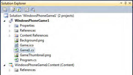
The Properties and References sections of the project will no doubt be familiar (and serve exactly the same purpose as in any other project you may work on). The rest of the items within the project deserve a little more explanation, however, so let's take a look at each of them.
First is the Content References item, which allows the project to read content (such as graphics, sound effects, or music files) that it needs to use in order to run the game. If you expand the Content References tree node, you'll see that it references the Content project (named SpritesContent in the example shown) that has also been created within your solution. We will examine the reason for having a separate Content project (and some of the things that you can do with it) later in this chapter.
Next is Background.png. This 173 × 173 pixel image provides a large graphic for your game, which will be present if the user pins it to the start screen. You should make sure that it provides an attractive and identifiable image of your game.
This is followed by Game.ico, a 32 × 32 pixel icon that will be used by your game executable when it is compiled. It defaults to an image of an Xbox controller. You will almost certainly want to change this for any finished game to help it stand out from the crowd.
Following this is the Game1.cs file that we have open in the code editor. We will be looking at this in much more detail during this and the following chapters.
GameThumbnail.png is next; it is a 64 × 64 pixel icon used when your game is displayed in the full application list and in the Windows Phone Marketplace (a topic we will discuss toward the end of the book). The default image for this looks like a dark-gray blob, but actually provides a shaded background into which you can draw your own imagery to help make your game identifiable. This image should be essentially the same as that from Background.png so the user can recognize the game in both the start screen and the application list.
Finally we arrive at Program.cs. If you open it in the code editor, you will see that it contains content similar to that shown in Listing 2-10.
Example 2.10. The default content of the Program.cs file
using System;

namespace Sprites
{
#if WINDOWS || XBOX
    static class Program
    {
        /// <summary>
        /// The main entry point for the application.
        /// </summary>
        static void Main(string[] args)
        {
            using (Game1 game = new Game1())
            {
                game.Run();
            }
        }
    }
#endif
}
The code is simple: creating an instance of the Game1 class that has been provided for us and calling its Run method. But before the Program class is defined within this source file, a compiler directive tells Visual Studio to build the class only if the WINDOWS or XBOX constants have been defined. For Windows Phone development, neither of these constants is defined (the constant WINDOWS_PHONE is defined instead). The end result is that this class won't be defined for Windows Phone XNA games.
Instead, XNA looks for the first class it can find that inherits from Microsoft.Xna.Framework.Game, which is the case for the Game1.cs that was created in our project. If you have multiple classes that inherit from Microsoft.Xna.Framework.Game, Visual Studio will raise a compilation error. You can actually resolve this by selecting a specific game class in the Project Properties window, but in practical terms there is little reason to have multiple game classes within the same project.
You will notice from the set of files present in the project that there are no forms or files representing any other user interface classes. XNA does not use anything analogous to forms, instead relying purely on graphics being rendered through program code.
Something else that may have been unexpected when you created the XNA project is the presence of the Content project. This project, which is initially empty, has the sole purpose of containing all the external data files (graphics, sound files, 3D models and so on) that you wish to use within your game.
So why is this created as a separate project? There are several reasons why it is useful:
The main reason is for performance. Our test project has a single graphic file, but full games can contain dozens of content files. Each time the project is compiled, all these files need to be processed by XNA in order to put them into a form that it can use. The content tends to be modified fairly infrequently, but the program code is modified in virtually every build. Putting the content into a separate project means that the processing of this content need only be performed each time the content actually changes, speeding up compile time for all the rest of the compilations.
Another benefit of a Content project is that it allows you to separate the content for different hardware targets. You may well want to use larger graphics on an Xbox version of a game than on a Windows Phone version, and maybe even larger still for high-end PC versions. Using separate Content projects allows you to create a project for each and keep the same code in your main game project.
If you have content that you wish to share between multiple games (a company logo, for example), it can be placed into a separate Content project and referenced by each of the game projects. Changes made to this Content project will then be reflected in all the games.
The way in which the game accesses the content is very simple. In the Game1 constructor of the game project we have been working on, you will find the line of code shown in Listing 2-11.
Example 2.11. Setting the RootDirectory property of the Content object
Content.RootDirectory = "Content";
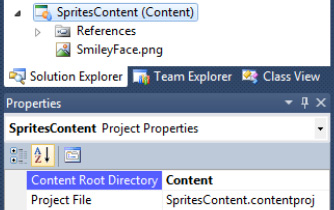
The value of "Content" that is set corresponds to the Content Root Directory property of the Content project, which you will find in the Properties window when the Content project's main node is selected in Solution Explorer, as shown in Figure 2-7. This is also shown in brackets after the project name. If you do decide to add multiple Content projects to your solution, ensure that each has a different Content Root Directory so that XNA knows where it can find each referenced asset.
Once the RootDirectory property has been set, you can access assets within that directory just by specifying their asset name, as we have seen already. If you wish to divide your assets into groups (perhaps by type, graphics, sounds, music, and so on), you can create subdirectories within your Content project by right-clicking the main project node and selecting Add / New Folder. When you place assets into these folders, you can access them either by setting the RootDirectory to include the subdirectory name or by including the directory name when calling the Content.Load function, as shown in Listing 2-12.
You have now seen how easy it is to draw a simple graphic to the screen, but sprites have a few more tricks in store. Let's examine some of the other properties and abilities of XNA sprites.
We have a choice of graphic file formats to use when loading images for use within our games. Some are distinctly better than others. Here is a summary of the main formats that can be used:
BMP (bitmap) files have a simple structure internally and are, therefore, easy for graphics libraries to interact with. One of the reasons for this simplicity is that they do not employ any form of compression at all. For this reason, BMP files can be huge in terms of file size compared with the other graphics formats that are available. BMP files do not offer any form of transparency. There are no compelling reasons to use BMP files, so please avoid using them wherever possible.
PNG (Portable Network Graphics) files, as used for the smiley face image in the previous example, are the most recently developed file format supported by XNA. They can store graphics using the full 24-bit color palette and are additionally able to support alpha (transparency) information. They compress their content to reduce the size of the graphic file. This compression is lossless, so no degradation of the image occurs as a result. For nonphotographic images, this is the file format that I recommend.
JPG (a contraction of JPEG, the Joint Photographic Experts Group that developed the format) files revolutionized the Web and have been an enabling technology in a range of other areas too, such as digital cameras. The format's strength is its ability to hugely compress images to file sizes that are dramatically smaller than their uncompressed originals, far more so than the PNG format is able to offer. The problem with this, however, is that JPG uses a lossy compression technique: after decompressing the image, you don't get back exactly what you started with. Compressed JPGs quickly start to exhibit graphics distortions, and this is most strongly apparent with graphics that contain highly contrasting areas of color, such as those within a computer game often do. JPG files can be useful for reducing the size of photographic images, but are not well suited to hand-drawn game graphics. Even with photographs, be careful not to compress the image to a point where distortion begins to appear.
One familiar graphic format that you may notice is absent from the list is the GIF (Graphics Interchange Format) file. XNA does not support GIF files. This is not really much of a loss because PNG files can do almost everything that GIF files can do, have better compression, support more colors (24-bit color as opposed to GIF's 8-bit color), and have proper alpha support. If you have a GIF file that you wish to use, convert it to a PNG file and use it in that format instead.
In the earlier example we drew the sprite at its original size. XNA can scale the sprite as we draw it, changing its size to make it smaller or larger. It can scale either uniformly (the sprite scales equally along the x and y axes) or non-uniformly (the x and y axes scale differently, stretching or squashing the image).
There are several overloads of the SpriteBatch.Draw method that support scaling in various different ways. The first and simplest of these allows us to specify the amount of scaling that should be applied to the sprite. The sprite width and height is multiplied by the provided value to determine the finished size, so passing a value of 1 will leave the sprite size unchanged, 2 will double it, and so on.
Note
Passing a scale value of 0 will cause the width and height to be multiplied by 0, with the result that your sprite will vanish completely. This is particularly important to remember when you aren't actually taking advantage of scaling but are using the other features of the Draw methods instead. Remember that to draw your sprite at its normal size, you need to pass 1 as the scale factor.
The version of Draw that we use to access this scale parameter takes quite a few more parameters than the version we used earlier, as shown in Listing 2-13.
Example 2.13. Rendering a sprite with scaling
spriteBatch.Draw(_smileyTexture, new Vector2(100, 100), null, Color.White, 0,
                               Vector2.Zero, 3.0f, SpriteEffects.None, 0.0f);
From left to right, the parameters are as follows:
The sprite graphic texture to render (as before).
The position to render at (as before).
The area of the sprite texture to render (we will look at this parameter in more detail in the "Partial Image Rendering" section in a moment). Passing
nulltells XNA to render the entire image.The render color (as before). We'll look at this parameter in the "Colorization" section coming up shortly.
The rotation angle. This is explained further in the next section.
The scaling factor. At last—this is where we tell XNA how much to enlarge or shrink the image.
Sprite effects. We'll look at these shortly.
Layer depth. This will be covered in a moment, too.
As you can see, this is quite a lot of extra data to specify, but as shown it is easy to pass values that result in these parameters having no effect.
In addition to the scaling factor, the origin parameter also has an effect on scaling. Listing 2-13 shows this passed as Vector2.Zero, which produces a coordinate of (0, 0). The origin has two immediate effects: it specifies which point within the image is actually being specified by the position parameter and it controls the point around which scaling takes place.
Let's begin with the first effect. When we discussed rendering sprites back in the example project, we saw that the position parameter set the top-left corner of the rendered sprite. If we use the origin parameter, this allows us to control the location within the image that is actually set by position. For example, if we set the origin to new Vector2(10, 20), the point 10 pixels across the image and 20 pixels down the image would appear exactly at the location specified by position.
This may not sound very useful, but it becomes more important when the second effect is considered because the origin point within the image also becomes the center of image scaling. As the image is scaled up or down, the origin point will stay in exactly the same place, while the rest of the image scales around it.
This can be seen in Figure 2-8, in which the dot indicates the origin of the differently scaled rectangular sprites. In the image on the left, the origin is set at (0, 0), so the sprites scale down and to the right. The middle image has the origin in the center of the rectangle, causing the sprite to keep the same center point as the rectangle is enlarged and reduced. The final image shows the origin at the bottom-right corner of the sprite, causing it to scale up and to the left. In all three images, the position parameter was passed as the same location.

It is also possible to scale with a negative factor, which will cause the image to be mirrored horizontally and vertically about the origin point.
The Draw call in Listing 2-13 allows just a single value to be passed for the scaling factor, which means that it only supports uniform scaling. Non-uniform scaling is no harder to achieve, however: we just substitute a Vector2 structure in place of the float that we used before. The Vector2 x value will represent the scaling on the horizontal axis, and its y value will represent the scaling on the vertical axis.
An example non-uniform scale using this approach is shown in Listing 2-14. This listing doubles the width of the sprite and halves its height.
Example 2.14. Rendering a sprite with non-uniform scaling
spriteBatch.Draw(_smileyTexture, new Vector2(100, 100), null, Color.White, 0,
                Vector2.Zero, new Vector2(2.0f, 0.5f), SpriteEffects.None, 0.0f);
The origin parameter behaves in exactly the same way when using this approach as it did for uniform scaling.
The final method for scaling a sprite uses a slightly different approach. Instead of specifying the position, an origin, and a scale factor, we instead define the overall rectangle into which the sprite is to be rendered.
Listing 2-15 shows a call to the Draw method that scales a sprite in this way. The top-left corner of the rendered sprite is at the coordinate (50, 50) and it has a width of 300 pixels and a height of 500 pixels. This puts the bottom-right corner at the coordinate (350, 550).
Example 2.15. Rendering a sprite to fill a defined rectangle
spriteBatch.Draw(_smileyTexture, new Rectangle(50, 50, 300, 500), Color.White);
Exactly which of these scaling approaches works best for you will depend on the way in which you are using the sprite. Sometimes it is best to use a scaling factor (particularly if you want the sprite to grow or shrink in size as the game progresses), although other times a destination rectangle may be the easier approach. Make sure you consider all the options to avoid creating unnecessary work for yourself.
Sprites also have the ability to be smoothly rotated to any angle you wish. The angle is specified by using either of the Draw calls shown in Listing 2-13 or 2-14, passing the angle for the appropriate parameter.
The angle is measured clockwise in radians, meaning that an angle of 0 is the right way up, PI / 2 is rotated a quarter of the way around to the right, PI is upside down, and 3 PI / 2 is rotated three-quarters of the way around.
Personally, I find working in radians quite unnatural and I much prefer working in degrees. XNA is here to help with this because it offers a very useful class named MathHelper, which is full of static functions to assist with graphics-related mathematical functions. One such function is ToRadians, which converts the supplied degrees angle into radians. Using this with the Draw function's rotation parameter makes providing the angle much easier.
Just as with scaling, the point around which the image rotates can be controlled using the origin parameter. Set this to the center of the sprite image to rotate on the spot or provide a different origin for off-center rotation. The origin can be completely outside the sprite area if you wish.
Listing 2-16 shows a call to Draw that rotates a sprite by 45 degrees around its center. The output from this call can be seen in Figure 2-9.

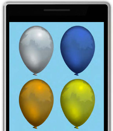
Throughout all the calls to Draw, we have passed through a Color parameter, and in each case it has been Color.White. We can pass different colors instead of white to tint the graphic that is being drawn. If we pass Color.Blue, the sprite will be shaded in blue, for example.
A very useful application of this feature is to allow a single graphic to be drawn in lots of different colors, without having to add all the different colored graphics individually into the Content project. If the source image is provided in grayscale, the tint can be used to display this in whatever color we want. You can see this in action in the TintedSprites example project, an image from which is shown in Figure 2-10 (though this obviously looks better in color!).
To understand just how the tinting works (and what kind of results you can expect from it), we need to discuss how colors are represented in computer graphics.
In XNA there are two ways that we can specify a color to use:
Using one of the named color values from
Microsoft.Xna.Framework.ColorSpecifying the individual levels of red, green, and blue that will make up the color
A large range of named colors is provided, from standard colors such as Black and Blue to those with more extravagant names including the sublime PapayaWhip and the unmistakable BlanchedAlmond. This list of named colors is actually the full list of X11 colors, which also form the predefined named colors used for HTML and Cascading Style Sheets (CSS). For further information about these colors, see the Wikipedia page at http://en.wikipedia.org/wiki/Web_colors where a full list and an example of each can be seen.
Alternatively, colors may be specified by providing the levels of red, green, and blue intensity (the additive primary colors) that are required to form the required color. Each of these is specified independently and ranges from 0 (no intensity) to 255 (full intensity). For example, creating a color with its red component set to 255 and its green and blue components set to 0 will result in a pure red. By varying the intensity of each color, all the available shades that the device is able to display can be created.
Note
There are various different models in which colors can be specified. In printing, the most common model is the CMYK model. CMYK is an abbreviation for "cyan, magenta, yellow, and key-black." Cyan, magenta, and yellow are the primary subtractive colors—so named because, when additional color is applied, they reduce the amount of light that is reflected and result in a darker color. The model that is most commonly used in computer devices is RGB, an abbreviation for "red, green, and blue." Red, green, and blue are the primary additive colors, which result in an increased amount of light when the colors are mixed together (so that, in fact, mixing all three results in white light). The .NET framework supports color specifications using the RGB model.
To create a color from red, green, and blue intensity levels, create a new Color structure and pass the intensity levels into its constructor. There are actually two ways in which the intensity levels can be specified: either as integer values from 0 to 255 as described, or as float values from 0 to 1. Exactly which of these approaches you prefer is up to you; they are functionally equivalent. Listing 2-17 shows an example of creating two identical Colorstructures, one using integer values and the other using floats.
Example 2.17. Creating colors from red, green, and blue intensity levels
Color myColor1 = new Color(255, 128, 0);
        Color myColor2 = new Color(1.0f, 0.5f, 0.0f);
Because we can specify 256 levels of each of the three color components, we can create colors from a total palette of 16,777,216 different colors (256 × 256 × 256 = 16,777,216). This is the same color depth as used on virtually all modern desktop PC displays. Because each of the three color components requires 8 bits of data (to store a value from 0 to 255), this is known as 24-bit color.
So how does all this apply to tinting? In order to apply a tint, XNA first reads the color of each pixel from the image using the float representation, using a value between 0 and 1 for each of the red, green, and blue components. It then obtains the tint color using the same float representation. The corresponding values for red, green, and blue are then multiplied together, and the resulting value is the color that is actually displayed on the screen.
Because the color white has RGB values of (1, 1, 1), the result of using white as a tint is that each pixel color component is multiplied by 1—in other words it is not changed, and the image is rendered untinted. If we used a tint color of black, which has RGB values (0, 0, 0), all the pixel color components would be multiplied by 0, resulting in the sprite appearing totally black. By using tint colors that have different levels of red, green, and blue—for example, orange has the RGB value (1, 0.5, 0)—we can cause the sprite to be tinted toward whatever color we wish.
Note that if the source image is not grayscale, however, it may not tint in the way you necessarily want. For example, if you have a sprite that consists of strips of red, green, and blue color, and you tint it using a solid blue color, the areas of red and green will turn completely black (because the intensity levels for red and green in the blue tint are 0). This is why a grayscale image is often the best to use when tinting.
Sprites can draw just a subsection of their images, too. One of the main uses for this is for animation: multiple animation frames can be placed into a single image, and then individual frames can be rendered to the screen in sequence to animate the sprite.
An example of how this can be used is in the AnimationFrames project. Its Content project contains a single image, Radar.png, which can be seen in Figure 2-11.
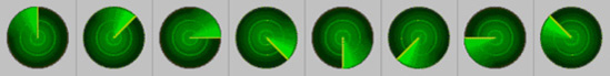
As this figure shows, there are eight individual images contained within the file. Each has exactly the same width (75 pixels), so we can draw any frame by locating its left edge and then drawing a section of the image that is 75 pixels wide. To find the edge, we take the animation frame number (from 0 to 7) and multiple it by the frame width (75 pixels). Frame 0 therefore has a left edge of 0 pixels, frame 1 a left edge of 75 pixels, frame 2 a left edge of 150 pixels, and so on.
Drawing a section of the image is easy and is achieved by passing a Rectangle structure to the sourceRectangle property of Draw. This defines the left and top corner of the rectangle within the source image, and also the width and height to copy. The code that performs the frame drawing in the AnimationFrames project is shown in Listing 2-18.
Example 2.18. Rendering a sprite using a source rectangle
_spriteBatch.Draw(_radarTexture, new Vector2(100, 100),
                   new Rectangle(_animationFrame * 75, 0, 75, 75), Color.White);
Although it is not shown in Listing 2-18, it is possible to combine the use of a source rectangle with scaling and rotation because all the versions of the Draw method that allow these operations to be specified also accept a sourceRectangle parameter. In fact, we have been passing this in all the examples using these techniques, except that we passed null to indicate that we wanted the whole image to be drawn rather than a subsection.
If overlapping sprites are rendered using any of the code samples so far, each will be rendered in front of the sprites already on the screen. Sometimes you need to order the sprites in a particular way so that some sprites appear in front of other sprites.
XNA provides an easy way to implement this. Some of the Draw overloads accept a float parameter called layerDepth, and we can pass a value for this between 0 and 1 to control which sprites appear in front of others. A value of 0 puts the sprite right at the front, whereas a value of 1 puts it right at the back.
The only catch to this is that layerDepth processing is disabled by default. To enable it, we need to pass some additional parameters to the SpriteBatch.Begin call. The parameter that switches this on is the sortMode parameter, which we will set to SpriteSortMode.BackToFront. It instructs XNA to draw the objects at the back first and then work toward the front, allowing each sprite to draw over the top of the sprites behind. When this parameter is passed, Begin also requires a value for its blendState parameter; we will pass BlendState.AlphaBlend, which is the default for this property when the overload of Draw with no parameters is used.
Listing 2-19 shows this effect in operation. Although the sprites are drawn from left to right (which would normally result in the rightmost sprite appearing in the front), we are specifying layerDepth values that put the leftmost sprite in front and the rightmost sprite at the back. You can find the full code for this in the LayerDepth example project.
Example 2.19. Drawing sprites with layerDepth sorting enabled
// Begin a sprite batch with BackToFront sorting enabled
        _spriteBatch.Begin(SpriteSortMode.BackToFront, BlendState.AlphaBlend);
        // Draw some sprites with different layerDepth values
        _spriteBatch.Draw(_smileyTexture, new Vector2(100, 100), null, Color.White, 0.0f,
Vector2.Zero, 1.0f, SpriteEffects.None, 0.0f);
        _spriteBatch.Draw(_smileyTexture, new Vector2(140, 100), null, Color.White, 0.0f,
Vector2.Zero, 1.0f, SpriteEffects.None, 0.5f);
        _spriteBatch.Draw(_smileyTexture, new Vector2(180, 100), null, Color.White, 0.0f,
Vector2.Zero, 1.0f, SpriteEffects.None, 1.0f);
        // End the sprite batch
        _spriteBatch.End();
The end result is shown in Figure 2-12.

The smiley face texture we have been using is circular, but sprites are always rectangular. Why is it then that we don't end up with a rectangular box drawn around the edge of the sprite?
The reason is that we are using an image with transparency information. Without this, the sprite would be drawn completely to the edges of its draw rectangle. Figure 2-13 shows an example of drawing the smiley face texture without any transparency. As you can see, it's not exactly the effect we want to achieve in most cases.

We have two techniques at our disposal for making transparent sections within our sprites: color keys and alpha channels. Let's take a look at each of these techniques. Examples of both techniques can be found within the Transparency example project.
Note
JPEG images are not recommended for use with either of these transparency techniques. JPEG's lossy compression means that colors are not stored accurately enough for color key transparency, and the information required for alpha channels is not supported by JPEG images. If you wish to use transparency, you will need to stick with PNG image files instead.
A color key provides the simplest mechanism for making areas of your sprite transparent, but it is less flexible than the alpha channel approach that we will discuss in a moment. A color key identifies a particular pixel color within your image that will be treated as transparent. Any and all pixels that exactly match the specified color will become completely transparent when your sprite is rendered, whereas all other pixels will be completely opaque.
By convention, the color fuchsia is by default used as the color key. This has full intensity of red and blue, and none of green, and is, by any other name, purple. This has been chosen as it is a relatively infrequently used color within computer graphics.
The ColorKey.png image in the Transparency example's Content project is set up to use a color key. As you will see when you run the project, the sprite is drawn as if it were circular, and all the rest of the rectangular sprite area is left untouched when the sprite is drawn.
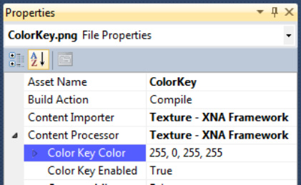
But why has XNA decided to use the color key? And how could we use a different color as the color key if we needed to use fuchsia in our graphic? The answer to these questions can be found in the Properties window for the ColorKey.png file within the Content project. If you expand the Content Processor property, you will find that hiding inside are properties named Color Key Enabled and Color Key Color, as shown in Figure 2-14. These default to True and 255, 0, 255, 255, respectively (the Color Key Color values represent the red, green, blue and alpha values of the transparent color). If you wish to disable the color key or change the key color, modify these properties as required.
Color key transparency is a quick and simple method, but it is binary: pixels are either fully transparent or fully opaque. Sometimes we want more control than that, allowing individual pixels in the image to have different degrees of transparency. We can achieve this using an alpha channel.
As already discussed, each pixel color within an image is made from varying the intensity of red, green, and blue. PNG images are able to store one final additional value alongside each pixel: the alpha value. This also ranges from 0 to 255, where 0 represents a fully transparent pixel (which will actually be completely invisible when drawn to the screen) and 255 (which represents a fully opaque pixel). The values inbetween form a smooth gradiation of transparency levels.
Although the end results of using an alpha channel are usually superior to those from color keyed graphics, the amount of effort required to set up the graphic can be much greater. For more information on how to use alpha channels in your graphics package of choice, please consult its documentation.
Tip
Most well-featured graphics packages allow you to work on an image's alpha channel. If you are looking for a flexible and powerful image editor on a budget, try the freeware application Paint.NET. Visit the web site at http://www.getpaint.net/ to download. Paint.NET has full alpha channel support, although it can take a while to get the hang of using it.
For images with alpha channels, there is no need to set up any properties within the Content project: XNA will automatically recognize and use the alpha data within the image. The Transparency example project displays two instances of a graphic with an alpha channel. The color data in the graphic is in fact completely white, but the alpha data contains a radial fade from opaque in the image center to fully transparent at the edges.
The project randomly changes the background color every few seconds. Note how the alpha channel images blend in with the background, taking on its color in their semitransparent regions. You can also see how the two overlapping images blend with one another rather than erasing the pixels of the sprite in the background.
Tip
Alpha channels can, of course, be used when tinting sprites, too. Try changing the color of one of the alpha channel sprites from Color.White to Color.Blue, for example, and see how the sprites now appear when the project is run.
Now that we have discussed alpha channels and transparency, we can revisit the sprite tinting feature that we discussed a few pages back.
You may recall that we could define a color for tinting by specifying the red, green, and blue intensity levels. But hold on; if PNG images can store alpha information as well as color information, can we use alpha values for tinting?
Well yes, we can. A further overload of the Color constructor allows an alpha value to be specified alongside the red, green, and blue values. If we set our SpriteBatch object up in the appropriate way and pass the alpha value as something other than 255 (or 1.0f, if you prefer the float-based version), the sprite will be drawn semitransparently. This can be used to smoothly fade objects in or out of the display, or to provide ghostly shadow effects in your games.
To use this effect, we first need to specify a different parameter when calling the SpriteBatch.Begin method. Pass the value of BlendState.NonPremultiplied for the blendState parameter. There are various methods that XNA uses to blend new graphics with those already on the screen, and this is the one that allows us to draw new sprites with varying levels of transparency.
Then it is simply a matter of providing an alpha level in your Color object: 0 for fully transparent; 255 for fully opaque. Listing 2-20 creates a series of smiley faces that are fully transparent on the left to opaque on the right. The results are shown in Figure 2-15.
Example 2.20. Drawing sprites with alpha tinting
// Begin a sprite batch with nonpremultiplied blending
        _spriteBatch.Begin(SpriteSortMode.Deferred, BlendState.NonPremultiplied);
        // Draw some sprites with different alpha tints
        for (int i = 0; i < 20; i++)
        {
            _spriteBatch.Draw(_smileyTexture, new Vector2(I * 20, 100),
new Color(255, 255, 255, i * 12));
        }
        // End the sprite batch
        _spriteBatch.End();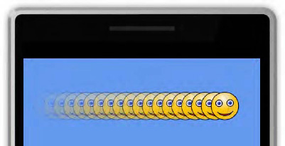
The example shown in Figure 2-15 can be found in the AlphaTinting project in the accompanying download.
Besides drawing individual graphics on the screen, there are various other useful effects that we can perform by using sprites. Let's take a look at a few of these effects: background images, fading to black, and fading between images.
Games with solid color backgrounds can look a bit dull, but we can liven things up by drawing a single sprite that precisely fills the background of the game area. Because the sprite results in the entire screen being redrawn, there is no need for the Draw code to clear the graphics device, which saves a little bit of graphics processing time.
The background is then drawn by specifying a render rectangle rather than a sprite position and ensuring that the rectangle fills the entire screen. We can actually obtain such a rectangle from XNA very easily by querying the Game.Window.ClientBounds property. This returns a Rectangle structure that corresponds with the dimensions and position of the game window.
Provided that we draw the background first (or use a layerDepth value that ensures it appears behind everything else), this will draw the background texture to fill the screen and allow all our other graphics to appear on top. The code to achieve this is shown in Listing 2-21.
Example 2.21. Using a sprite to create a background image
protected override void Draw(GameTime gameTime)
    {
        // No need to clear as we are redrawing the entire screen with our background image
        //GraphicsDevice.Clear(Color.CornflowerBlue);

        // Begin the spriteBatch
        _spriteBatch.Begin();
        // Draw the background image
        _spriteBatch.Draw(_backgroundTexture, this.Window.ClientBounds, Color.White);
        // Draw the smiley face
        _spriteBatch.Draw(_smileyTexture, _smileyPosition, Color.White);
        // End the spriteBatch
        _spriteBatch.End();

        base.Draw(gameTime);
    }
This can be seen in action in the BackgroundImage example project. Note that we use a JPEG image for the background because it is a photograph, which reduces the size of the compiled application—just make sure that the picture is of the same aspect ratio as the screen (tall and thin) so that it isn't distorted when it is displayed. Figure 2-16 shows the output from this project.

A common and useful effect seen on TV and in films is the fade to black, which simply involves fading away everything on the screen to blackness. This is great for scene transitions because it allows the content of the entire screen to be updated without any jarring movement. It can add a layer of presentational sparkle to games, too, perhaps fading from the title screen into the game or fading between one level and the next.
We can implement a fade to black very easily by first drawing all the content on the screen and then rendering a full-screen sprite over the top, colored black and with variable alpha intensity. To fade to black, we start with an alpha value of 0 (transparent), at which point the sprite will be invisible, and fade to 255 (opaque), at which point the sprite will completely obscure everything on the screen. Once we reach this point, the rest of the scene can be changed in whatever way is appropriate, and the alpha level faded back toward zero to fade the scene into visibility again.
Because the texture we need for the sprite is just a solid color, we can actually create the texture in code rather than having to add an image to the Content project. We can create a new texture by specifying the device on which we will render it (a reference to which is stored in the Game class's GraphicsDevice property) along with its width and height. We can create the texture with a width and height of just 1 pixel because XNA will happily stretch it to whatever size we want.
Perhaps surprisingly, we will tell XNA to make the texture's only pixel white rather than black because we can tint it black when we draw it. Setting the texture up this way means that we could also tint it any other color should we wish: fading to white, green, or powder blue as suits our game.
First then, let's look at the code that creates the texture, which can be seen in Listing 2-22. This is extracted from the project's LoadContent method. It creates the Texture2D object and then calls its SetData method to pass in the colors for the texture pixels. If the texture were larger, this would set a pixel for each provided array element, working horizontally across each row from left to right and then vertically from top to bottom. Our array has just a single element to match the pixels in the texture.
Example 2.22. Creating the fader texture
// Create the texture for our fader sprite with a size of 1 × 1 pixel
        _faderTexture = new Texture2D(GraphicsDevice, 1, 1);
        // Create an array of colors for the texture -- just one color
        // as the texture consists of only one pixel
        Color[] faderColors = new Color[] {Color.White};
        // Set the color data into the texture
        _faderTexture.SetData<Color>(faderColors);
The texture is then used in the Draw method, as shown in Listing 2-23. In this example, we draw a number of smiley faces onto the background and then draw the fader in front. The alpha level for the fader is stored in a class variable named _faderAlpha, which is faded between 0 and 255 in the Update method.
Example 2.23. Drawing the fader texture
protected override void Draw(GameTime gameTime)
    {
        GraphicsDevice.Clear(Color.CornflowerBlue);

        // Begin the spriteBatch
        _spriteBatch.Begin(SpriteSortMode.Deferred, BlendState.NonPremultiplied);

        // Draw the smiley face sprites
        for (int i = 0; i < _smileyPositions.Length; i++)
        {
            _spriteBatch.Draw(_smileyTexture, _smileyPositions[i], Color.White);
        }

        // Draw the fader
        _spriteBatch.Draw(_faderTexture, this.Window.ClientBounds,
new Color(0, 0, 0, _faderAlpha));
// End the spriteBatch
_spriteBatch.End();
base.Draw(gameTime);
}Each time the fader reaches maximum opacity, the positions of the smiley faces are all updated, but we never see them move because they are always obscured when this takes place. For the full code and to see this running, take a look at the FadeToBlack example project.
Similar to the fade to black effect is the fading between images effect. It is essentially the same technique, but it uses two sprites containing images rather than one sprite containing solid color. By using a series of images, slideshow effects can be set up, providing a very pleasant transition between each pair of images.
The effect can be seen in the FadeBetweenImages example project. Although XNA provides a beautiful smooth transition between the images, unfortunately a picture doesn't speak 1,000 words in this case because it doesn't look very impressive at all on paper—it needs to be seen in motion.
We can take a quick look at the code, though. We set up an array of three different background textures and load them in the LoadContent method. To make the fade work, we store the index through the array of the current background image (which is the image that will be fading away) in the _backgroundImageIndex variable and the fader image (which is the image that will be fading into view) in the _faderImageIndex variable. These are initially given the values 0 and 1, respectively.
The Draw method, shown in Listing 2-24, should look very similar because it's just like the previous listing. Note that the tint color is now white rather than black so it shows in its normal colors.
Example 2.24. Drawing the fading images
protected override void Draw(GameTime gameTime)
    {
        // No need to clear as we are drawing a full-screen image
        //GraphicsDevice.Clear(Color.CornflowerBlue);

        // Begin the spriteBatch
        _spriteBatch.Begin(SpriteSortMode.Deferred, BlendState.NonPremultiplied);
        // Draw the background image
        _spriteBatch.Draw(_backgroundTextures[_backgroundImageIndex],
this.Window.ClientBounds, Color.White);
        // Draw the fader
        _spriteBatch.Draw(_backgroundTextures[_faderImageIndex], this.Window.ClientBounds,
new Color(255, 255, 255, _faderAlpha));
        // End the spriteBatch
        _spriteBatch.End();

        base.Draw(gameTime);
    }
The Update code simply increments the value of _faderAlpha, waiting for it to exceed 255. When this happens, it is reset back to 0, and the image index variables are incremented. We use the % modulus operator to automatically reset the index variables back to 0 once they reach the defined image count. The fade can, of course, be made faster by adding a greater value to _faderAlpha; to slow it down, the variable could be converted to a float and a fractional value added. The relevant part of the code is in Listing 2-25.
Example 2.25. The Update code to fade between the series of images
// Increment the opacity of the fader
        _faderAlpha += 1;
        // Has it reached full opacity?
        if (_faderAlpha > 255)
        {
            // Yes, so reset to zero and move to the next pair of images
            _faderAlpha = 0;
            _backgroundImageIndex = (_backgroundImageIndex + 1) % IMAGE_COUNT;
            _faderImageIndex = (_faderImageIndex + 1) % IMAGE_COUNT;
}Most games need to display text while they are running, providing everything from the player's score through to menus and game information pages. XNA provides a very easy-to-use mechanism for showing text on the screen, so let's see what it can do and how we use it.
Fonts can cause all sorts of problem with regard to licensing. The vast majority of fonts that are included with Windows or can be downloaded from the Internet have license terms attached that prevent you from redistributing them in your own games.
Fortunately, Microsoft has helped us out by licensing a number of fonts that can be used and distributed in your Windows Phone games without any threat of legal action. We will therefore concentrate on how these particular fonts can be used in your games.
The available fonts are summarized in Table 2-1.
Table 2.1. Fonts licensed for use in Windows Phone games
Name | Example | Variations |
|---|---|---|
Andy | Bold | |
Jing Jing | Regular | |
Kootenay | Regular | |
Lindsey | Regular | |
Miramonte | Regular, Bold | |
Moire | Light, Regular, Bold, ExtraBold | |
Motorwerk | Regular | |
News Gothic | Regular, Bold | |
OCR A Extended | Regular | |
Pericles | Light, Regular | |
Pescadero | Regular, Bold | |
Quartz MS | Regular | |
Segoe Keycaps |  | Regular |
Segoe Print | Regular, Bold | |
Segoe UI Mono | Regular, Bold | |
Wasco Sans | Regular, Italic, Bold, Bold Italic |
As you can see, there are some diverse typefaces present. Note that some of them (Jing Jing, Motorwerk, Quartz MS) have no lowercase letters; they have display capitals instead, while Pericles uses small versions of its capital letters instead of lowercase letters.
The Variations column in the table shows the different font variations that are fully supported within the fonts. To use the Regular, Bold, or Italic versions, place the required word into the Style element within the .spritefont file. For Wasco Sans' Bold Italic, use Bold, Italic as the style. For the other variations (Light or ExtraBold), suffix the variation to the font name (for example, Moire ExtraBold) and leave the Style element set to Regular. Fonts that do not show bold or italic variations can still be set to be bold or italicized by setting the Style element as required, but they will be programmatically converted into the requested version rather than using a design from the font definition itself and so might not look quite as good.
If you do want to use other fonts, you can easily do so, but please do be careful that you have the appropriate permission first. There are freely licensed fonts around if you search for them on the Internet, but check the license terms carefully!
Before we can display any text, we must first embed the font into our program. XNA and Visual Studio between them take all the pain out of doing this, and it can be mostly achieved with just a few mouse clicks.
Just like all the image resources we have been using, the font is added into the Content project. To add a font, right-click the main Content project node and select to Add a New Item. Select the SpriteFont template in the Add New Item window and give the font a name—it's a good idea to name it after the font that you plan to use, as shown in Figure 2-17.

Once the font has been added, a .spritefont file will appear. This is an XML document that describes to the compiler the details of the font that is to be used. When the Content project compiles, it reads the font from disk and converts it into a bitmap image to embed in your project. It is this image of the font rather than the font itself that is therefore used by your program. The .spritefont file describes how this bitmap is to be constructed.
There isn't all that much within the file to change; the available items are as follows:
FontNameprovides the name of the font to embed. Set it to one of the XNA licensed fonts mentioned in the previous section or to any other font installed in Windows that you are licensed to use.Sizesets the size of the font to be used to generate the bitmap. If you choose a large value, a higher-quality bitmap will be generated, but it will require a lot more space and memory to process, which is particularly wasteful if the font doesn't need to be displayed in large sizes. Smaller values lower the resource requirements, but result in blocky text appearing if the font is rendered larger than its default size. You will need to find a balance between size and appearance when setting this. The size is specified in points rather than in pixels; due to the way points are handled by XNA, you can find the approximate pixel size by adding one-third to the point size (a point size of 12 will result in a pixel size of 16 pixels).Spacingsets the number of pixels that will be left as a horizontal gap between each rendered character. Increasing it above 0 can make the text look very spacedout, so use with caution.UseKerningcontrols whether font kerning is used. Kerning is the process whereby characters are moved closer together if it can be achieved without the characters colliding. For example, the letters "AV" can be positioned so that the boxes containing each letter overlap, without the letters themselves touching. Kerning generally produces much more natural-looking text, so should usually be left enabled.Styleallows the font style to be set toRegular,Bold, orItalic(it can also be set toBold, Italicto combine these two styles).CharacterRegionsprovides one or more ranges of characters to be included within the generated font bitmap. The smaller the number of characters, the smaller the resulting bitmap. If, for example, you knew that you would be including only uppercase letters in your game, you could omit the lowercase letters from the font and thus reduce the resource requirements. MultipleCharacterRegionelements can be included in the outerCharacterRegionselement if required.DefaultCharacteroptionally provides a placeholder character that will be used any time a text string is printed that contains characters outside of the definedCharacterRegions. Without this, XNA will throw an exception if any such attempt to draw a string is made.
With the .spritefont file configured per your requirements, Visual Studio will automatically build the bitmap font each time the Content project is compiled.
Our font is built and so we are ready to print with it to the screen. This is straightforward and painless, and involves first loading the font from the Content project, just as we did with our sprite textures.
This is achieved by once again calling the Content.Load method from within our game's LoadContent procedure, but indicating this time that we want it to return a SpriteFont object, as shown in Listing 2-26.
Example 2.26. Loading the spritefont whose asset name is Miramonte
// Load the spritefont
        _fontMiramonte = Content.Load<SpriteFont>("Miramonte");
To print the text to the screen we once again use the SpriteBatch object, calling its other method for drawing: DrawString. A number of overloads for this are available, but essentially they are all the same except that some accept a String parameter, whereas others accept a StringBuilder, some expect parameters to control rotation and uniform scaling, and yet others allow non-uniform scaling.
The simplest version, which isshown in Listing 2-27, simply prints the text at the coordinate (100, 100) in white text.
Example 2.27. Using DrawString to display text to the screen
_spriteBatch.Begin();
        _spriteBatch.DrawString(_fontMiramonte, "Hello world", new Vector2(100, 100),
Color.White);
        _spriteBatch.End();
The text appears on the screen just as you would expect (see Figure 2-18). The specified coordinate refers to the top-left corner of the displayed text.

All the other features available to sprites are available to spritefonts too, allowing us to display text in different colors (including with variable alpha levels to allow text to fade in and out of display), rotated to different angles, or scaled to whatever size is required. The syntax for drawing text with these effects applied is essentially just the same as for drawing sprites.
We also have the ability to specify an origin for the text. When we drew sprites, we could easily identify the width and height of the sprite by querying the Width and Height properties of the Texture2D object used to provide the sprite image. But for text, the size will be different for every string we draw depending on the string being displayed.
To overcome this, the SpriteFont object provides a very useful function called MeasureString. When the function is passed the text to be displayed, it returns a Vector2 structure with the required text width stored in its X property and the text height in its Y property. This allows us to easily determine the dimensions of the rendered string, and this value can be used as the basis of calculating DrawString Origin parameter. Finding the center point is especially easy because the Vector2 can be multiplied or divided by a scalar value, resulting in its X and Y values being multiplied or divided by the provided value. The center point can thus be obtained by simply dividing the result from MeasureString by 2.
Tip
XNA can include line breaks within strings, both when drawing and measuring. Insert them into a string in C# using the
character sequence.
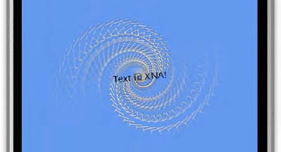
Listing 2-28 shows an extract from the Text example project that does something a little more exciting-looking than the simple "Hello world" text. It measures a text string so that it can determine its center point and then uses it to draw a series of text strings to the same position on the screen, with each string a little larger, further rotated, and more faded than the last.
Example 2.28. A text-based graphical effect using rotation, scaling, and alpha blending
// Calculate the size of the text
        textString = "Text in XNA!";
        textsize = _fontMiramonte.MeasureString(textString);
        // Draw it lots of times
        for (int i = 25; i >= 0; i--)
        {
            // For the final iteration, use black text;
            // otherwise use white text with gradually increasing alpha levels
            if (i > 0)
            {
                textcolor = new Color(255, 255, 255, 255 - i * 10);
            }
            else
            {
                textcolor = Color.Black;
            }
            // Draw our text with its origin at the middle of the screen and
            // in the center of the text, rotated and scaled based on the
            // iteration number.
            _spriteBatch.DrawString(_fontMiramonte, textString, new Vector2(240, 400),
textcolor, MathHelper.ToRadians (_angle * ((i + 5) * 0.1f)),
textsize / 2, 1 + (i / 7.0f), SpriteEffects.None, 0);
        }
The code actually loops backward so that the most faded/rotated/enlarged text is displayed first; each additional iteration draws a more focused version on top of it. The color is finally set to black for the very last iteration to make the text easier to read.
The DrawString call may look a bit complex, but if we break it down it's really very simple. We specify the spritefont to use, the text to write, and the position of the text origin, which is hard-coded at (240, 400) for simplicity in this example. After the color, we then provide the rotation angle, which is modified for each iteration so that each piece of text appears at a slightly different angle. The origin is specified next, simply by passing the textsize value retrieved from MeasureString, divided by 2 so that we obtain its center point. Finally we specify the scale, also set to change for each iteration, the SpriteEffect (which can be used to flip text upside down or back to front), and the layer depth.
Once this is all put together, the output is as shown in Figure 2-19. This can also be seen in action in the Text example project, which is another example that looks much better in motion than in a static screenshot.
Although the display of text is a basic requirement, XNA nevertheless provides a variety of options to make its display interesting and flexible.
We've now covered most of the fundamental options available for 2D rendering, but there are a few important details still left to look at, so let's run through these now.
All the examples so far have operated in so-called windowed mode, which in the context of Windows Phone simply means that the status bar is visible at the top of the screen. In many instances users may prefer to have this available because it gives them a window into the phone: they can see their battery level, their signal reception level, and so on. Some games may benefit from having the game run in full screen mode, however, with this bar hidden. It is usually polite to offer a configuration option so that this mode can be configured per user preference.
Setting full screen mode is easy; just add the line of code shown in Listing 2-29 to your Game class's constructor:
Example 2.29. Starting up in full screen mode
// Set the graphics device manager into full screen mode
        _graphics.IsFullScreen = true;
If you wish to change the full screen state of your game at a later time, the easiest way is to call the GraphicsDeviceManager's ToggleFullScreen method. You can check the current state at any time by reading back the IsFullScreen property value.
All the examples that we have looked at in this chapter used portrait orientation for displaying their graphics. This is the orientation that the user is likely to be using for general-purpose interaction with the device, and if your game works well in this orientation it is a good idea to allow your game to run in this arrangement.
If your game would benefit from a landscape orientation, however, this is easy to implement. In fact, the default behavior of XNA is to present the game in landscape mode.
Windows Phone 7 devices have special hardware present to support orientation, which means that they cost absolutely no processing time whatsoever.
Let's look at the options for supporting different orientations within your games.
To set a game to run in portrait mode, we can set the width and height of the back buffer in the game class constructor so that its height is greater than its width. We can set the width to 480 and the height to 800 to match the device resolution, as shown in Listing 2-30.
Example 2.30. Setting the back buffer for portrait orientation
// Display using portrait orientation
        _graphics.PreferredBackBufferWidth = 480;
        _graphics.PreferredBackBufferHeight = 800;
With this configuration active, the game will always appear in portrait mode, regardless of how the device is physically rotated. You can test rotation on the emulator by clicking the rotate buttons that appear to the right of the device window and see how the graphics on the screen respond. With the game running in portrait mode, the graphics will display sideways when the device is in a landscape orientation.
You can see this in effect by running the Orientation sample project. This also displays the name of the orientation that the device is currently using, the size of the back buffer, and the size of the game window. Notice that they do not change when the device is rotated.
To operate your game in landscape orientation, don't specify any preferred back buffer size in the class constructor; the game will default to landscape mode. Try commenting out the back buffer configuration in the Orientation project and run it to see the results.
If you leave the device or the emulator in portrait orientation, the display will appear sideways because the game is now supporting only landscape orientations. Note that if you switch the device over between being rotated to the left and to the right, it automatically rotates the screen content to match. The Current orientation display from the program will switch between LandscapeLeft and LandscapeRight as you do this.
The game itself doesn't need to know anything about such a rotation because the screen size is absolutely unchanged.
You may wish to support your game in both landscape and portrait orientations. Doing so is easy to accomplish from the point of view of the phone, but may introduce additional work into your game because you will probably need to resize or reposition your game elements to fit into the new window dimensions.
To enable all possible orientations, comment out the code that sets the preferred back buffer size and replace it with the code shown in Listing 2-31.
Example 2.31. Allowing landscape and portrait orientations
// Allow portrait and both landscape rotations
        _graphics.SupportedOrientations = DisplayOrientation.Portrait |
                                DisplayOrientation.LandscapeLeft |
                                DisplayOrientation.LandscapeRight;
If you run the project now, you will find that it automatically adjusts to whatever orientation the device is held in.
One important point is the way that the Window size and Back buffer size values are reported by the example project. The window size remains completely unaffected by the rotation because at heart the device is always operating in portrait mode, so this is the size that it considers its window to be. The back buffer size (retrieved from the BackBufferWidth and BackBufferHeight properties of the _graphics.GraphicsDevice.PresentationParameters object) always reflects the dimensions of the window as it is actually being rendered. If you are supporting rotation, be careful to read the buffer size in the correct way.
You can, of course, provide any set of orientations that you wish for the SupportedOrientations property. Setting it to just DisplayOrientation.LandscapeLeft would prevent portrait or landscape-right orientations from being displayed. Generally if you are allowing landscape orientation, you should allow both modes so that users can hold the device in whichever way they are comfortable with.
To change the supported orientations after the game has started, set the SupportedOrientations property as needed and then call the _graphics.ApplyChanges method. The updated orientations will become immediately effective.
If you need to detect the orientation changing so that you can update your game accordingly, the easiest way to do it is to subscribe to the game window's OrientationChanged event. This is fired each time the orientation changes, and the new orientation can be retrieved from the Window.CurrentOrientation property. The Orientation example project uses this event to display the new orientation to the debug window each time it changes.
Compared with modern game consoles, Windows Phone 7 devices are fairly low-powered in terms of graphical capability, despite the hardware that they have at their disposal. Yet they still run at a fairly high resolution: 480 × 800 pixels is a substantial amount of screen data to update.
In many cases, the hardware will be entirely capable of handling this, but when the graphic updates are more intense the phone may struggle. To assist with this scenario, the device has a hardware image scaler built in, which enables XNA to render at any size that it likes, allowing the scaler to increase the size of the rendered graphics so that they fill the screen. Just as with rotation, special hardware is present to perform this task, so it takes no processor time whatsoever. The scaler smoothes the graphics as it processes them, so it avoids displaying pixelated graphics. The scaler is particularly effective with fast-moving graphics, which further helps to disguise the scaling that is taking place.
To use the scaler, we just set the preferred back buffer size in the game constructor to whatever size we need. If the game is running in portrait mode, we can scale everything to twice its size by using the code shown in Listing 2-32. Note that the size provided here is exactly half the actual screen size. This means that we can render into the screen area 240 pixels wide by 400 pixels high (instead of the normal 480 × 800 pixels) and still have it fill the screen. This is one-quarter of the volume of pixels, resulting in a lot less work for the device to do.
Example 2.32. Double-size scaling in portrait mode
// Scale up by 2x
        _graphics.PreferredBackBufferWidth = 240;
        _graphics.PreferredBackBufferHeight = 400;
If your game is using landscape mode, set the preferred back buffer size so that the width is greater than the height, as shown in Listing 2-33. This is the correct approach if using both landscape and portrait modes via the SupportedOrientations property too: XNA will automatically swap the back buffer width and height when switching into portrait mode, so always provide the buffer size with the dimensions that will be used for the landscape display orientation.
Example 2.33. Double-size scaling in landscape mode
// Scale up by 2x
        _graphics.PreferredBackBufferWidth = 400;
        _graphics.PreferredBackBufferHeight = 240;
The scaler can also work with smaller resolutions than this if desired, but the more dramatic the scaling, the more pixelated and distorted the final image will be.
To change the scaling after the game has started, set the preferred back buffer size as required, just as we have seen in the constructor, and then call the _graphics.ApplyChanges method. The scaler will immediately start or stop work as required.
The update/draw loop that XNA employs is generally very good for presenting a game to the screen and offers great opportunities for rich-looking graphic updates. But sometimes the graphics being drawn to the screen aren't actually moving at all. XNA is unaware of this, however, and continues to clear and repaint the same identical scene frame after frame, using the CPU and graphics hardware in the process and wasting the battery as a result.
These is, however, a way to indicate to XNA that it doesn't need to redraw the screen and can just re-present the most recently drawn screen. This is achieved simply by calling the Game class's SuppressDraw method from within the Update function.
A simple approach to managing this is to create a bool variable within Update called objectsMoved, initially set to false. As soon as your Update code causes anything to happen that needs the screen to be redrawn, it sets this variable to true. At the end of the function, the code can then check this variable and call SuppressDraw if it still contains its initial false value.
In this chapter, we have covered a lot of XNA's capabilities for 2D rendering. In the next chapter, we will build on these capabilities and start to develop a model for flexible game development.
Please feel free to spend some time experimenting with what you have learned so far. You already have lots of useful and flexible graphical techniques under your belt, and the more familiar and comfortable you can get with these the better. Try out using some of these effects and see what you can produce yourself.