
Three-dimensional graphics have completely revolutionized computer games over the last decade. For some time before this, it was obvious that 3D games were going to be big, with games such as DOOM creating moving images the likes of which had never been seen before.
When dedicated 3D graphics hardware began to appear back in the late 1990s, graphics were transformed even more, moving away from the blocky and grainy images that players had become accustomed to and replacing them with smooth textures, dynamic lighting, and enormous levels of detail. Game worlds really started to look like real worlds.
Mobile graphics hardware, even in dedicated devices such as Sony's PlayStation Portable, are trailing a fair distance behind the power of modern PC graphics hardware, and this applies to the hardware within Windows Phone 7 devices, too. The phone's capabilities are still quite sufficient to create very impressive 3D scenes and games, and the platform is perfectly capable of providing dynamic and complex 3D gaming opportunities for your audience.
This chapter examines how to bring the third dimension to life.
The vast majority of 3D games use a perspective projection to display their graphics. Just as in the real world, this projection simulates the application of perspective to objects rendered within the game, so that objects that are farther away appear smaller than objects that are closer.
In addition to this obvious size effect, the more subtle effects of perspective are picked up intuitively by the brain and add a substantial feeling of depth to the rendered scene. The sides of a cube will very slightly narrow due to the effects of perspective as they increase in distance from the viewer, allowing the brain to automatically determine the exact position in which the cube is situated.
When we use a perspective projection in XNA, we create as part of the Effect object initialization a three-dimensional volume known as a viewing frustum. The shape of the frustum is that of a rectangular cone with its tip cut off. A demonstration of such a frustum is shown in Figure 7-1.
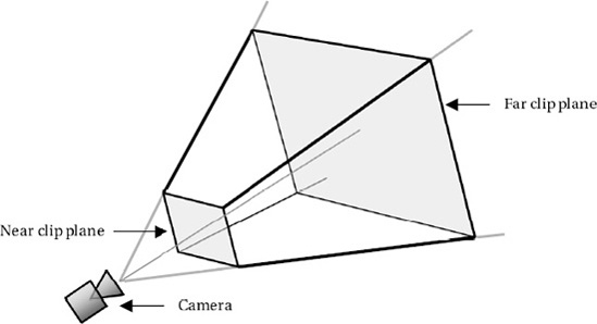
The frustum can be visualized in the real world by imagining yourself looking through a window. Outside the window you can see the ground and various objects. The farther away into the distance you look, the wider the area that you can see. Objects that are too far to the side, above, or below will be hidden by the window frame.
Objects that fall inside the volume described by the frustum are visible to the camera (and would be visible through the window). Objects that fall outside the frustum volumes are hidden from the camera (and would not be able to be seen through the window).
The near and far clip planes are also taken into account when deciding whether objects are visible. Objects nearer to the camera than the near clip plane are deemed to be too close and are excluded from rendering. Similarly, objects farther than the far clip plane are too far away to be seen and are once again excluded.
Note
When we specify an object's z position (its distance into the screen), the negative z axis represents movement away from the player and into the screen: as an object's z coordinate decreases, so it moves farther away. When we specify the distance of the near and far clip planes, however, they are specified purely as distances from the camera and are therefore positive values.
When XNA transforms the objects that fall inside the frustum from the 3D space in which we have defined our world into the 2D space that is actually presented on the screen, it takes into account how much of the width and height of the frustum is filled by any particular object. An object will occupy a greater proportion of the frustum when it is positioned toward the near clip plane than it will at the far clip plane (see Figures 7-2 and 7-3). Figure 7-2 shows two identically sized objects within the viewing frustum. Figure 7-3 shows the same scene after the perspective projection has taken place to transform the scene into two dimensions for display on the screen. Note that the object at the near clip plane appears substantially larger than the one at the far clip plane.


In addition to the clip planes, the frustum is defined by two more pieces of information: the viewing angle and the aspect ratio.
The viewing angle defines the angle, in degrees, between the camera and the upper edge of the frustum (the angle on the y axis). Changing this angle will make the overall shape of the frustum expand or compress, causing the apparent reduction in size of objects farther away to be increased or decreased.
Figure 7-4 shows two viewing frustums from the side: the first with a viewing angle of 45 degrees; the second with 22.5 degrees. The distance of the near and far clip planes is the same in both cases.
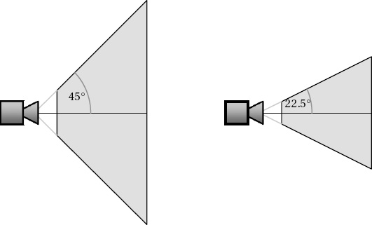
Figure 7.4. Two viewing frustums, one with a 45-degree viewing angle (left) and one with a 22.5-degree angle (right)
Consider how objects that fall into these two frustums will be projected. On the left, objects can deviate further from the center of the frustum and still be seen by the camera. Objects that are farther away will become rapidly smaller as their size relative to the extent of the frustum becomes less and less. On the right, objects farther from the center will leave the frustum more quickly and so will disappear off the edge of the screen. Distant objects will appear larger than with the first frustum as they occupy a greater proportion of the frustum's area.
Exactly what you should specify for the viewing angle will potentially vary from one game to the next. An angle of 45 degrees is usually a safe value. Setting the angle too low can make it appear that everything is closer to the player than it really is, which can result in the game feeling uncomfortable to play.
Tip
Some interesting effects can be achieved by varying the viewing angle at strategic times within the game. For example, you could provide a transition between two scenes by rapidly decreasing the viewing angle down to zero, switching the scene, and then increasing the angle back to its original value. This process will cause everything in the center of the screen to appear to zoom toward the player and then zoom back again after the scene change. "Slow-motion" effects can often be accentuated by slightly reducing the viewing angle while they are active.
The second piece of information that the viewing frustum requires is the aspect ratio, which is calculated by dividing the display width by its height. The aspect ratio allows the viewing angle on the x axis to be calculated by XNA in response to the explicit angle that we provided for the y axis. The aspect ratio, together with the viewing angle and the distance of the clip planes, provides everything that is needed to fully describe the frustum.
XNA actually performs the perspective transformation with the use of another matrix. You might recall that in the Initialize function of the example classes from Chapter 6, the code shown in Listing 7-1 is present to set up the default projection matrix.
Example 7.1. Creating the viewing frustum matrix
// Calculate the screen aspect ratio
float aspectRatio =
        (float)GraphicsDevice.Viewport.Width / GraphicsDevice.Viewport.Height;
// Create a projection matrix
Matrix projection = Matrix.CreatePerspectiveFieldOfView(MathHelper.ToRadians(45),
                                                        aspectRatio, 0.1f, 1000.0f);
You should be able to spot all the information that we have discussed as being required for the viewing frustum. The work of generating the projection matrix is performed by the static Matrix.CreatePerspectiveFieldOfView function. The parameters that it expects to be passed are as follows, in the following order:
fieldOfView: the viewing angle for the projectionaspectRatio: the aspect ratio of the display width/heightnearPlaneDistance: the near clipping plane distancefarPlaneDistance: the far clipping plane distance
In Listing 7-1, a viewing angle of 45 degrees is specified, along with the aspect ratio calculated from the game's ViewPort, and near and far clipping planes of 0.1 and 1000, respectively.
When rendering, XNA first calculates the positions of all the object vertices in 3D space and then uses the projection matrix to transform them into 2D coordinates to display on the screen.
If you want to change the viewing angle (or any of the other properties of the frustum), you can simply set a new projection matrix into the effect's Projection property before rendering your objects.
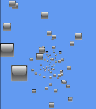
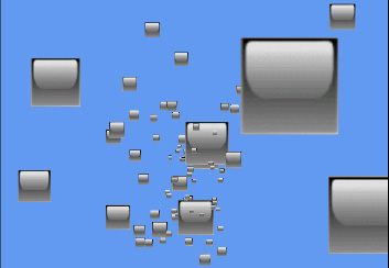
The Perspective example project in this chapter's accompanying download shows how objects move when a perspective projection is applied. The code is very simple; it creates a number of objects with random x, y, and z coordinates. Each time the objects update, they add to their PositionZ value, moving them closer to the screen. When they get to a value of 0, they add 100 to move them back into the distance. A screenshot from the demo can be seen in Figure 7-5.
Moving objects around our 3D game world is great, but we need to be able to create 3D objects too; so far, we've worked just with flat rectangles. This section discusses how solid objects can be created.
The objects that we have been drawing up to this point have defined four vertices, all with a z value of zero, and used a triangle strip to combine them into the rendered shape. When we move into three-dimensional objects, we probably can't use triangle strips. Every triangle of a triangle strip shares an edge with the previous triangle, and with 3D objects we will very quickly find that we can't draw objects in this way. Instead, we will use a list of individual triangles, which gives us the flexibility to draw whatever triangle we need wherever we need it.
To start with we will define our 3D object by manually providing all its vertex coordinates. This is fairly straightforward for simple shapes, but does quickly become impractical once we want to move on to more complicated objects. We'll use a simple cube for the time being, however, and will look at how complicated geometry can be constructed in the "Importing Geometry" section in the next chapter.
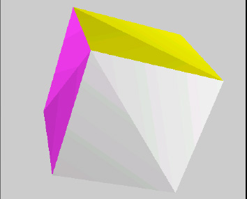
A cube consists of six square faces and eight vertices. As each square needs to be rendered as two triangles, we end up with a total of 12 triangles to draw, as shown in Figure 7-6.

Because we will draw individual triangles rather than use a triangle strip, we need to specify each triangle coordinate individually. This means that when two triangles share a single coordinate, we actually need to specify the coordinate twice, once for each of the triangles. As a result, we have to provide a total of 36 vertices, three for each triangle. Because there are only eight distinct vertices forming the cube, this respecification of vertices is quite wasteful and requires XNA to perform the same calculations over and over again. We will look at a more efficient rendering method in the "Vertex and Index Buffers" section coming up shortly.
To build the vertices of the cube, we simply declare an array of vertices and add to it sets of three values, representing the vertices of each of the triangles. The coordinates for the front face of a unit-size cube can be seen in Listing 7-2. Note that the z coordinate in each coordinate is 0.5, meaning that it extends half a unit toward the viewpoint.
Example 7.2. Defining the front face of a cube
// Create and initialize the vertices
        _vertices = new VertexPositionColor[6];

        // Set the vertex positions for a unit size cube.
        int i = 0;
        // Front face...
        _vertices[i++].Position = new Vector3(-0.5f, −0.5f, 0.5f);
        _vertices[i++].Position = new Vector3(-0.5f, 0.5f, 0.5f);
        _vertices[i++].Position = new Vector3(0.5f, −0.5f, 0.5f);
        _vertices[i++].Position = new Vector3(0.5f, −0.5f, 0.5f);
        _vertices[i++].Position = new Vector3(-0.5f, 0.5f, 0.5f);
        _vertices[i++].Position = new Vector3(0.5f, 0.5f, 0.5f);
Plotting out these coordinates shows that we have indeed formed a square that will form the front face of the cube, as shown in Figure 7-7.
The array is extended to cover all the faces of the cube, extending into the 3D space by using positive and negative values for the z positions. The full array is not included here because it is fairly large and not particularly interesting, but it can be seen in full inside the CubeObject.BuildVertices function in the ColoredCubes example project. The code in this function also sets the vertices for each face to be a different color to make the cube look nicer.
Tip
The CubeObject class declares its array of vertices as static, so only a single instance of the array exists and is shared by all instances of the CubeObject class. Because the contents of this array are identical for every class instance, declaring the array in this way means that .NET allocates memory for the vertices only once for the whole application instead of once per cube object, saving some precious memory.
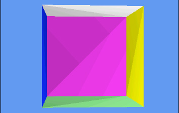
With all the vertices defined, the object can be rendered using exactly the same code used for flat objects. The result is shown in Figure 7-8.
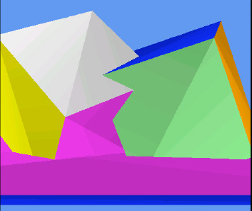
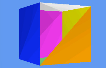
Fundamentally, that is all there is to it! If you run the ColoredCubes example project, you will see how this basic object can be easily reused within the game engine to create a much more visually exciting scene, as shown in Figure 7-9. This example creates 100 cubes, gives each a random angle and position, and then rotates them around the y axis, resulting in a swirling tornado of colored blocks.

Something you might have observed in both the Perspective and ColoredCubes examples is that the objects nearer the camera all appear in front of the objects farther away. When we displayed our graphics using sprites, we had to put in some effort to provide a LayerDepth value for each sprite in order to facilitate depth sorting like this. There is no equivalent functionality in these 3D projects, though, and yet the objects still all appear in the right places. Why does this happen?
The answer is that XNA has a built-in mechanism for ensuring that objects in the front of the scene automatically hide any objects that fall behind them. This happens regardless of the order in which objects are drawn: objects drawn behind existing objects can still be partially (or totally) obscured even though they might be rendered after the object in front.
XNA achieves this effect by using a feature known as the depth buffer. It can be enabled or disabled, and is enabled by default. When rendering simple 2D graphics, the depth buffer might be unnecessary, but in 3D scenes it is almost certain to be required.
Just as the color of each rendered pixel is written into a graphical buffer for display on the screen, so the distance into the screen of each rendered pixel is written into a corresponding depth buffer when the buffer is enabled. For each individual pixel that it is about to render, XNA checks the depth of the pixel against the depth already stored in the buffer. If it finds that the new pixel is farther away than the pixel already in the buffer, the new pixel is not rendered to the screen; otherwise, the pixel is rendered and the depth buffer updated to remember the new depth of the pixel.
This per-pixel depth checking can be clearly seen in the DepthBuffer example project, shown in Figure 7-10. This figure displays two rotating cubes, positioned so that they intersect one another; and below them a third cube, squashed to form a "floor." Observe the behavior when the cubes intersect one another: at every single pixel position, the frontmost cube surface is always displayed.
The way that intersecting objects are handled can be very useful. For example, if you want to draw a landscape scene with water such as lakes or an ocean, the ground can be drawn in its entirety (the parts that are above the water level and also those that are below) and then a single semitransparent flat plane can be drawn at the water level across the entire scene. Only those parts of the scene that are below the water level will be affected by the water plane, providing a reasonably convincing approximation of water with very little complexity or processor cost.
Most of the time when you are rendering objects in your game, you will want the depth buffer to be available and active. Without it, distant objects will appear in front of nearer objects, destroying the illusion of the 3D world that you are trying to render.
On some occasions, however, you might want to render without updating the depth buffer. Examples include rendering background scenery that should never obscure any of the other graphics rendered and objects that are rendered in front of a scene to provide overlay content such as status bars or health displays.
The depth buffer can be temporarily disabled by setting the GraphicsDevice.DepthStencilState property to DepthStencilState.None. After this property has been set, graphics that are rendered will entirely ignore the depth buffer, neither observing values that are stored in it nor updating the values when new objects are rendered. To restore the normal behavior of the depth buffer, set the property back to its default value: DepthStencilState.Default.
You can see the effect of disabling the depth buffer by inserting the code from Listing 7-3 at the end of the LoadContent function in the Perspective example project.
Example 7.3. Disabling the depth buffer
// Disable the depth buffer
        GraphicsDevice.DepthStencilState = DepthStencilState.None;
Once the depth buffer has been disabled, you will find that the objects appear in the order that they are rendered rather than being sorted by their depth. This can be seen in Figure 7-11, in which some of the smaller, more distant shapes are clearly being displayed in front of the larger closer objects.
Note
If you want to entirely disable the depth buffer, you can set the _graphics.PreferredDepthStencilFormat property to DepthFormat.None in your game class constructor. This setting will initialize the graphics device without creating a depth buffer, which can save you some memory and processing overhead if you have no need for it.
There is another mode that can be set for the depth buffer: read-only mode. In this mode, XNA will observe the values in the depth buffer when rendering objects and will use it to prevent objects from being drawn if they are behind existing objects, but the depth buffer will not be updated in response to rendered objects.
This mode might seem like an unlikely feature to need, but it has various uses. One such use is for drawing particles in a 3D scene. We'll discuss particles in more detail in the next chapter, but they can be used for creating effects such as sparks, fire, and smoke. Although it is important that these correctly appear behind objects in the scene, we need to ensure that they don't obscure one another or else they won't display correctly.
XNA can be set to use a read-only depth buffer by setting the GraphicsDevice.DepthStencilState property to DepthStencilState.DepthRead. Don't forget to set it back to DepthStencilState.Default once you are finished with this mode.
In some situations you might want to clear the values stored in the depth buffer. This might be the case if you are drawing two scenes, one in front of the other, and want to prevent each one from interfering with the other. The first scene can be drawn (with the depth buffer active and working), the depth buffer then cleared, and the second scene then drawn. The depth data from the first scene will not interfere with the second scene at all.
To clear the depth buffer, we can call the GraphicsDevice.Clear method, just as we do at the start of the game's Draw function, but instead of simply passing a color we pass some additional parameters that tell it to clear only the depth buffer, not the graphics that have been rendered. The code for clearing the depth buffer can be seen in Listing 7-4.
Example 7.4. Clearing the depth buffer
GraphicsDevice.Clear(ClearOptions.DepthBuffer, Color.White, 1, 0);
Because the Clear method's first parameter is set to ClearOptions.DepthBuffer, only the depth buffer will be affected. We still have to pass a color (which will be ignored) and a stencil value (which we are not using), but the value 1 passed for the depth buffer tells XNA to set the buffer so that the depths are all considered as being at the very back of the viewing frustum. Subsequently drawn objects will therefore appear in front of this far depth and will not be obscured by previously drawn objects.
The depth buffer might not work exactly as you expect when it comes to drawing semitransparent objects. Although XNA's alpha blending feature can merge together objects that are being drawn with those already on the screen, the depth buffer can store only a single depth for each pixel. This means that, if you draw a semitransparent object and then draw an object behind it, the object behind will be completely eliminated by the depth buffer, even though the first object was transparent.
There are several approaches that can be employed to handle this. The first is to draw all your transparent objects so that those in the back of your scene are rendered first. This will ensure that objects in the front do not obscure those behind.
The second approach is to draw all your opaque objects first and then switch the depth buffer into DepthRead mode before drawing the transparent objects. This way the transparent objects will not obscure anything subsequently drawn behind them.
The final option is to use the AlphaTest effect (instead of the BasicEffect that we have been using so far), which can update the depth buffer only for pixels that match certain conditions in terms of their calculated alpha values. We will examine this effect in more detail in the next chapter.
Exactly which of these approaches is best will depend on what your game is drawing. Bear this limitation in mind when creating transparent objects in 3D space.
Hidden Surface Culling
When we draw solid opaque objects such as cubes, the inside of the cube is completely obscured from view. XNA is unaware of this, however, and would potentially continue drawing the inside faces of the cube. This is a waste of processing power because it would unnecessarily compare and update the inside faces with the depth buffer, and if the faces at the back are processed before those at the front it would also actually render them, only to subsequently draw over them completely with the outer faces of the cube.
You probably won't be surprised to hear that XNA has a solution for this problem—and it's nice and easy to use, too.
XNA can work out whether each triangle is facing toward us (as the front face of the cube is) or away from us (as the back face of the cube is). It does this based on how the triangle is actually rendered, not just how its vertices were defined, so that, as a triangle rotates, the direction in which it is facing will change. Those triangles that are found to be facing away from us are culled and are not considered for inclusion in the depth or color buffers, saving all the work that would otherwise have been involved in checking and updating them.
In order for XNA to be able to determine the direction in which the triangles are facing, we need to give our triangle vertices to it in a particular way. When we define the triangles, we ensure that, when the front of the triangle is facing toward us, the vertices are provided such that they appear in a clockwise direction. Figure 7-12 shows two triangles, one whose vertices are defined in clockwise order (on the left) and the other in counterclockwise order.
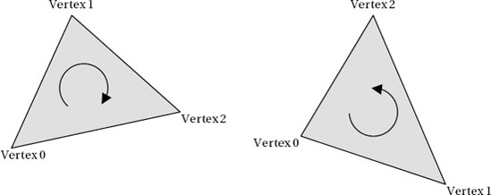
Given these two triangles to render, XNA will by default display the one on the left, not the one on the right. If we rotate them around so that their backs are toward us, the triangle on the left would not display, and the triangle on the right would appear.
Note
Remember that the vertices must appear in clockwise order when the triangle is facing you. When we define a cube, the rear face is initially facing away from us, so the triangles would appear to be in counterclockwise order instead. If the cube were rotated around so that the back face was oriented toward us, the vertices would then appear to be clockwise, as we need them to be.
If you look back at the vertices defined for the front face of the cube in Figure 7-7, you will see that both of the triangles have their vertices defined in clockwise order. This is by design, of course. With our triangles specified correctly, XNA will automatically ignore those triangles that face away from us.
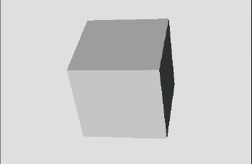
The HiddenSurfaceCulling project draws yet another cube, but this time it omits the final triangle from the cube (it tells DrawUserPrimitives to draw 11 triangles instead of 12), resulting in a triangular hole. We can look through this hole to the interior of the cube to see exactly what XNA is drawing for the reverse sides of the cube triangles.
If you run this project, you will see that the orange side of the cube that contains the missing triangle shows nothing behind it whatsoever (see Figure 7-13). Clearly, XNA shows the triangles only when they are actually facing toward us.

Sometimes it is useful to draw the rear surfaces of triangles, too. If you have objects that are completely flat and need to be viewed from in front or behind, or if you have objects that are hollow and whose interior can be seen, we can configure XNA to render both surfaces of each triangle.
To instruct XNA to render in this way, we need to disable surface culling. Culling is controlled by the GraphicsDevice.RasterizerState.CullMode property, which accepts one of these values: CullCounterClockwiseFace (the default), CullClockwiseFace (the reverse; culls faces that are defined in clockwise order), or None (the value we need here; none of the faces is culled).
Just as with the BlendState and SamplerState objects we saw in the last chapter, the RasterizerState object's properties all become read-only once the object has been set into the GraphicsDevice. We therefore can't update the properties of the existing object. Instead, we create a new object, configure it as required, and then set the whole object into the GraphicsDevice, as shown in Listing 7-5.
Example 7.5. Disabling hidden surface culling
// Create and activate a new RasterizerState with a different cull mode.
        RasterizerState rs = new RasterizerState();
        rs.CullMode = CullMode.None;
        GraphicsDevice.RasterizerState = rs;
You will find this code present but commented out within the HiddenSurfaceCulling project's Initialize function. Uncomment it so that it becomes active and then run the project again. Now you will find when the orange face is toward you that you can see through the missing triangle into the fully rendered interior of the cube, as shown in Figure 7-14.
The important thing to remember with hidden surface culling disabled is that the interior faces are being calculated and compared against the depth buffer even when they are completely hidden from view. When hidden surface culling was enabled, the interior faces were discarded immediately as XNA knew that they faced away and therefore didn't need to be checked against the depth buffer at all.
The final culling mode, culling clockwise faces, can be useful if you are importing model files (as we will learn to do in the next chapter) that have been defined with their faces counterclockwise instead of clockwise. Some modeling applications will define triangles in this way, and this is in fact the default culling mechanism used by OpenGL. The easiest way to deal with such objects is to swap the culling mode.
When the culling mode doesn't match the order with which the vertices have been defined, XNA will render just the inside of the object, hiding all the triangles that face toward you. This can result in potentially useful effects, though they can be visually disorientating. Try modifying the example project code so that it culls clockwise faces and running it again. You will now see the inside of the cube, as shown in Figure 7-15.
We're making good progress in our journey into 3D rendering, but there are some inefficiencies in the approach that we have used so far that it would be wise to address before we go any further. These can be addressed by using two new constructs: vertex buffers and index buffers. Let's take a look and see what they can do for us and how they are used.
All the techniques discussed in this section can be seen in the VertexAndIndexBuffers example project. This project adds three cubes to the scene, one of each of the techniques that we are about to explore.
In all the examples we have used so far, we have called the DrawUserPrimitives function to render our objects, passing it an array of vertices containing the object geometry. This works just fine, but is not the most efficient way of rendering. In order for the graphics hardware to use the vertex data, all the vertices must be transferred into the graphics memory. Just as we saw with repeated texture copying in earlier chapters, this data transfer can have a negative impact on performance.
We can address this performance issue by using a vertex buffer, which allows the vertex data to reside permanently within the graphics hardware. The advantage of this approach is that we can switch between vertex buffers with much less overhead than copying vertex data arrays.
A cube defined using a vertex buffer can be found in the VertexBufferCubeObject class. There are only a couple of differences between this class and the cube classes that we have looked at previously. First of all, a new static class-level variable has been defined of type VertexBuffer and with the name _vertexBuffer. When the class finds that the vertices have not been initialized, it creates them as before, but then also uses them to initialize the vertex buffer, as shown in Listing 7-6.
Example 7.6. Creating and initializing a VertexBuffer object
// Have we already built the cube vertex array in a previous instance?
        if (_vertices == null)
        {
            // No, so build them now
            BuildVertices();
            // Create a vertex buffer
_vertexBuffer = new VertexBuffer(game.GraphicsDevice,
typeof(VertexPositionColor), _vertices.Length, BufferUsage.WriteOnly);
_vertexBuffer.SetData(_vertices);
}The parameters passed to the VertexBuffer constructor are as follows, in this order:
graphicsDevice: the graphics device to which this vertex buffer will be renderedvertexType: the type of vertex being added to the buffervertexCount: the number of vertices to be added to the bufferusage: special usage flags
Most of these parameters should be self-explanatory. We know the vertex count because we've already built an array of vertices, so we can simply read the array size for the vertexCount parameter. The usage parameter needs a little additional explanation, however. It can be passed as either None or WriteOnly. The first of these options allows the vertex data to be retrieved at a later time (using the VertexBuffer.GetData function), but results in less efficient usage of the buffer in the graphics hardware. The WriteOnly option optimizes the buffer memory usage, but makes it impossible to read the vertex data back. It is unusual to need to read the data back (in this example, we have it in a separate array, anyway), so unless you need to read the data from the buffer, you should always specify WriteOnly.
This object creation results in an initialized but empty vertex buffer. The vertex data is copied into it by calling the SetData function, passing the vertex array as a parameter.
The buffer is now ready for use, and to render it we need to make some small changes to the object's Draw function. Prior to drawing we must tell the graphics device which vertex buffer it should render. Only a single vertex buffer can be set at any time, so it must be specified before the drawing instruction is executed. The buffer is set into the device, as shown in Listing 7-7.
Example 7.7. Setting a vertex buffer into the graphics device
// Set the active vertex buffer
        effect.GraphicsDevice.SetVertexBuffer(_vertexBuffer);
To render with the active vertex buffer, we use a different drawing method. Previously we had been calling DrawUserPrimitives and passing in the vertex array as a parameter. To render using a vertex buffer, we instead call DrawPrimitives. No vertex data needs to be passed because the vertex buffer from the graphics device will be used. We just need to tell XNA the primitive type, the start vertex, and the primitive count, just as we did before. The code to render the vertex buffer is shown in Listing 7-8.
Example 7.8. Drawing the active vertex buffer
// Draw the object
        foreach (EffectPass pass in effect.CurrentTechnique.Passes)
        {
            // Apply the pass
            pass.Apply();
            // Draw the object using the active vertex buffer
            effect.GraphicsDevice.DrawPrimitives(PrimitiveType.TriangleList, 0, 12);
        }
Other than these changes, the code and approach is identical to the examples we have already used.
In order to draw the cube shown in the previous examples, we have had to provide the same vertex coordinates to XNA multiple times. As we discussed earlier, a cube has 8 vertices, and yet in our examples we are creating our vertex array with 36 vertices in it, 6 for each face (consisting of 3 vertices for each of the 2 triangles used to draw the face).
This configuration of vertices is, of course, quite wasteful in terms of processing resources because we are calculating the exact same vertex position many times.
XNA provides an alternative mechanism for providing the list of vertices that allows the number of repeated identical coordinates to be reduced. Instead of creating each vertex independently of the others, we can instead provide a list of just the unique vertices and then separately tell XNA how to join them together to make the triangles that it is to render. The list of vertex numbers that specifies how to join the vertices is simply stored as an array of numbers.
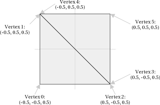
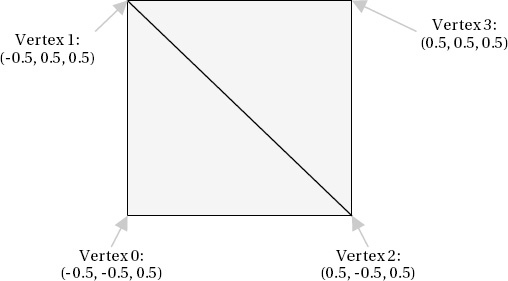
Consider again the front face of the cube that we saw in Figure 7-7. If we were to specify just the unique vertices, the vertex count would be reduced from the previous six to four. The four vertices are shown in Figure 7-16.
Although this new set of coordinates allows the vertices to be defined, we no longer have the information required to join them together to form the rendered triangles. At this point, the index array makes an entrance. To draw the front face, we need two triangles, and the vertex indices for each are as follows:
First triangle: 0, 1, 2
Second triangle: 2, 1, 3
Just as before, the triangle is formed by specifying its vertices in clockwise order so that hidden surface culling can hide the triangles when they are facing away from the viewer.
The only additional complexity with this approach is that vertices do not only store a position; they also store colors, texture coordinates, and other information (as we will see in the next chapter). Just because two vertices share the same location, it doesn't necessarily mean that they are identical.
Each vertex position in our cube will be part of three different faces (because each corner of the cube has three squares attached to it), and each face in our example is a different color. We will therefore need to repeat the vertices for each face, even though they are in the same position, because they have different colors.
This still allows us to reduce the vertex count from the original 36 (6 vertices per face x 6 faces) to a much more efficient 24 (4 vertices per face x 6 faces). The two redundant vertices within each square face are eliminated, reducing the vertex count by one-third.
As a result, the code required to build the vertex array now needs only to specify the unique indexes. The beginning of the code to generate these vertices, from the IndexedCubeObject class, can be seen in Listing 7-9. Compare this code to the code in Listing 7-2, and you will see that the repeated vertices are no longer present.
Example 7.9. Specifying vertex data for indexed rendering
// Set the vertex positions for a unit size cube.
        i = 0;
        // Front face...
        _vertices[i++].Position = new Vector3(-0.5f, −0.5f, 0.5f);
        _vertices[i++].Position = new Vector3(-0.5f, 0.5f, 0.5f);
        _vertices[i++].Position = new Vector3(0.5f, −0.5f, 0.5f);
        _vertices[i++].Position = new Vector3(0.5f, 0.5f, 0.5f);
In order to join the vertices together, we need to build the array of indices. XNA allows them to be stored either as an array of short values (permitting a maximum of 32767 vertices), or as an array of int values (with a maximum vertex count exceeding 2 billion), but on Windows Phone only short values are supported. This vertex limit still allows for very complex objects and is unlikely to present any practical limitation; it also saves memory by requiring two bytes per index instead of four.
For rendering a triangle list as we are, the array needs to be given sets of three indices in order to identify the three vertices for each triangle. The BuildIndices function sets them all up, and a small section can be seen in Listing 7-10. The resulting data is stored in the static class-level _indices array.
Example 7.10. The start of the index array creation
private void BuildIndices()
        {
            int i;

            // Create and initialize the indices
            _indices = new short[36];

            // Set the indices for the cube
            i = 0;
            // Front face...
            _indices[i++] = 0;
            _indices[i++] = 1;
            _indices[i++] = 2;
            _indices[i++] = 2;
            _indices[i++] = 1;
            _indices[i++] = 3;
            // Back face...
            _indices[i++] = 4;
            _indices[i++] = 5;
            _indices[i++] = 6;
            _indices[i++] = 5;
            _indices[i++] = 7;
            _indices[i++] = 6;
Note that we store 36 elements in the array: 6 faces x 2 triangles x 3 vertices = 36 elements in total. The first triangle is formed from the vertices at positions 0, 1, and 2; and the second triangle from the vertices at positions 2, 1, and 3—exactly as described in Figure 7-16. The array then continues to form another triangle from vertices 4, 5, 6; and another from vertices 5, 7, 6, and so on for all the triangles in the cube.
This is clearly quite a lot more work to set up than simply providing the stand-alone list of vertices, and in many cases the benefit of this approach will be negligible. In more complex objects, it can provide a noticeable performance boost, however. This indexed rendering approach can be taken advantage of without having to enter pages and pages of index numbers when geometry is read from external model files (as we will see in the next chapter) and also if you should write code that programmatically generates vertex coordinates and indices.
To render the cube using the index data, we call the DrawUserIndexedPrimitives function in the Draw function rather than DrawUserPrimitives. In addition to the DrawUserPrimitives parameters, this call also expects the index array to be provided and an offset through the index array from which it should start processing (which we will pass as 0 to specify that it should be processed from the beginning). The code for this call is shown in Listing 7-11.
Example 7.11. Rendering the cube using the index array
// Draw the object
        foreach (EffectPass pass in effect.CurrentTechnique.Passes)
        {
            // Apply the pass
            pass.Apply();
            // Draw the object using the active vertex buffer
            effect.GraphicsDevice.DrawUserIndexedPrimitives(PrimitiveType.TriangleList,
                                           _vertices, 0, _vertices.Length, _indices, 0, 12);
        }
This approach results in unnecessary processing of identical vertices to be eliminated in the rendered object.
Vertex buffers and indexing provide optimizations to the way in which our objects are calculated, and to get the best of both worlds we can use them both at the same time. When we render an indexed vertex buffer, the vertex buffer itself is created exactly as we have already seen, but the indexes are specified in a slightly different way. Instead of storing them just as an array, we instead place the array data into an IndexBuffer object.
This combined approach can be seen in the VertexAndIndexBufferCubeObject class. The vertex and index data is created exactly as it was for indexed rendering, with the reduced number of vertices (24 instead of 36) and the index array joining them together into the finished object. In the class constructor, both of these arrays are set into buffer objects, as shown in Listing 7-12.
Example 7.12. Creating a vertex buffer and an index buffer
// Have we already built the cube vertex array in a previous instance?
       if (_vertices == null)
       {
           // No, so build them now
           BuildVertices();
           // Create a vertex buffer
           _vertexBuffer = new VertexBuffer(game.GraphicsDevice,
typeof(VertexPositionColor), _vertices.Length, BufferUsage.WriteOnly);
_vertexBuffer.SetData(_vertices);
// Create the index array
BuildIndices();
// Create an index buffer
_indexBuffer = new IndexBuffer(game.GraphicsDevice, typeof(short),
_indices.Length, BufferUsage.WriteOnly);
_indexBuffer.SetData(_indices);
}The parameters required when creating the index buffer are as follows:
graphicsDevice: the graphics device to which this index buffer will be renderedtype: the type used for each index array element (shortorint)indexCount: the number of indices to be added to the bufferusage: special usage flags—NoneorWriteOnly, just as with the vertex buffer
This object creation sets up everything that is required to render the indexed vertex buffer. To actually draw it, we need to tweak the Draw function again.
Just as with the vertex buffer example, we need to provide the vertex buffer to the graphics device using the SetVertexBuffer function. Additionally, we now need to provide the index buffer into the graphics device's Indices property.
With these objects set in place, we render this time by calling the DrawIndexedPrimitive function. No vertex or index data needs to be passed because the function reads both of these from the objects set into the graphics device. Listing 7-13 shows the complete code to draw the cube using this approach.
Example 7.13. Drawing indexed vertices from a vertex buffer
public override void Draw(Microsoft.Xna.Framework.GameTime gameTime, Effect effect)
    {
        // Prepare the effect for drawing
        PrepareEffect(effect);

        // Set the active vertex and index buffer
        effect.GraphicsDevice.SetVertexBuffer(_vertexBuffer);
        effect.GraphicsDevice.Indices = _indexBuffer;

        // Draw the object
        foreach (EffectPass pass in effect.CurrentTechnique.Passes)
        {
            // Apply the pass
            pass.Apply();
            // Draw the object using the active vertex buffer
            effect.GraphicsDevice.DrawIndexedPrimitives(PrimitiveType.TriangleList, 0, 0,
                                                                _vertices.Length, 0, 12);
        }
    }
This approach provides the greatest efficiency for rendering in XNA because it reduces the calculation of redundant vertices and prevents unnecessary copying of vertex data within the device memory.
Up to this point, all the colors used in our examples have been directly specified within our program code. This gives us a high level of control over the appearance of the graphics, but leads to a flat and cartoony look to the graphics. To add a further degree of realism to the objects that we render, we can use XNA's lighting features.
This section examines the lighting capabilities and explores how they can be used within our games.
XNA offers the facility to place up to three different lights into the game world and use these to illuminate the objects that are rendered. When lighting is switched on, the way in which objects are colored is altered from the behavior we have seen so far. XNA applies lighting to our objects by calculating the amount and color of light that falls onto each vertex and actually adjusts the vertex colors based on the result of this.
The outcome is that we can generate highly dynamic and realistic-looking shading on our objects. The minor downside is that because XNA implements lighting by taking control of coloring the object vertices, we can't specify vertex colors ourselves. We can still apply textures to our objects just as before, but vertex colors cannot be used.
Although we are no longer able to directly color vertices, we can still use different colors within a texture to provide coloring to different sections of our objects, so this is not necessarily as big a problem as it might at first sound.
Additionally, the DiffuseColor property can still be used to change the overall color of the objects being rendered. This is also known as the material color as it defines the color of the object. This works alongside the colors of lights that we place within the scene, allowing colors of lights and objects to be set independently. This provides a fair degree of flexibility with regard to how our objects are lit.
The following sections will discuss how lights and materials can be used within our game worlds.
A number of different types of illumination are available to shine onto our objects. Any or all of the illumination types can be applied to XNA's lighting model, and the color of each type of illumination can be specified independently.
Let's take a look at each of the illumination types that a light can use.
The simplest type of light is ambient light, which is light that comes from all directions at once and falls equally on to all parts of each object rendered. It is completely flat in intensity, leaving no bright or dark areas on the objects that it illuminates.
In the real world, the closest analogy to ambient light is the light that is reflected from all the objects in the environment. If you are in a room with a single light source, those areas of the room that are not in direct line of sight from the bulb still receive some light from their surroundings. This is the illumination that ambient light seeks to simulate.
When an ambient light is present, all vertices will be equally lit by the appropriate ambient light level.
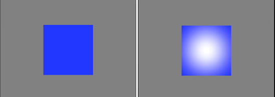
An example object illuminated with ambient light can be seen in Figure 7-17. The figure shows a 3D cylinder with a medium-intensity ambient light applied and no other lighting. Note how the object appears just as a silhouette: no variation of light intensity can be seen anywhere within the object.

XNA's default ambient light is black, meaning that no ambient light appears within the rendered scene at all.
Diffuse light is reflected by an object based on how the object is angled toward the light source. If an object is rotated so that its faces are directly toward the light source, the faces will radiate the light with a high intensity. As they rotate away from the light, the intensity fades away.
The light is radiated equally in all directions, so the viewpoint from which the object is seen has no effect on the intensity of the lit surfaces. This is how an object with a matte surface would behave in the real world, as opposed to a reflective surface that would reflect more or less light depending upon the observation viewpoint.
An example object illuminated with diffuse light can be seen in Figure 7-18. The figure shows the same cylinder with a bright diffuse light situated directly to its right. Note that the object illumination increases as the object surface becomes more directly angled toward the light source.

Specular light is also reflected by an object based upon its angle with regard to the light source, but this type of illumination radiates light more like a mirror: light is reflected from the surface based on the angle of the surface relative to the viewer and light source.
If the light source is in the same location as the viewpoint, and a surface also faces directly toward the viewpoint, the specular light will radiate intensely. As soon as the surface rotates away from the viewpoint, the specular light will rapidly fall away. If the viewpoint and light source are in different locations, those faces that are angled directly between the two will radiate light most brightly, just as a mirror would.
This behavior allows objects to be given a "shine" or "highlight" that can make for very realistic looking objects.
An example object illuminated with specular light can be seen in Figure 7-19. The image shows the same cylinder with a bright specular light situated directly to its right. Note that the object illumination increases as the angle of the cylinder reflects our viewpoint toward the light, where the surface of the cylinder is at about a 45-degree angle from the viewpoint. As the surface deviates from this angle, the light intensity rapidly drops away.

Just as lights emit different types and intensities of light, so can objects reflect different types of light in different colors. For example, a red object in the real world is red because it reflects any red light that falls upon it, and absorbs the green and blue light.
In XNA we can set the color and intensity of light reflected from each individual object by setting the object material. Just as each light can have different colors for ambient, diffuse, and specular light, so we can define the intensity and color that objects reflect for each different type of light.
Let's take a look at the different material properties and then we will examine exactly how lights and materials interact with each other.
As the material's ambient property controls the amount of ambient light reflected, so its diffuse property controls the amount of diffuse light reflected. This can be set to white to reflect all the light that reaches the object, or it can be changed in order to absorb and reflect different elements of the color instead.
We have already discussed the diffuse material in the "Tinting Objects" section in the last chapter.
The material's specular color controls the amount of specular light that is reflected from the object. Setting the material's specular color to white will reflect all specular light that arrives at the object, whereas setting it to black will absorb and therefore completely disable the specular element of the light, preventing any shine effects from displaying on the object.
In addition to controlling how much of the specular light is reflected, XNA also offers control over the focus of the specular highlight. Low specular power values (values up to around 4 or 5) will result in a very soft specular component, reflecting lots of light back. As the value increases, the specular light becomes more and more focused, requiring faces to be angled more directly toward the light source before any reflection is made. There is no specific upper limit for the specular power value, but as it begins to reach into the hundreds, its effect becomes so slight that the specular light effects begin to disappear.
The final material property allows us to set an emissive color. This property is used to specify a color that is then simulated as originating from the object, allowing it to have its own illumination independently of that of the lights around it.
Normally if an object has no light shining on it, it will appear completely black, but emissive colors allow the basic object color to be set even when it is not illuminated by any light at all.
It should be noted, however, that rendering an object with an emissive color set does not make the object into a light source itself. It will not add any light to the rest of the scene or cause any other objects to be illuminated in any way.
Now that you understand the role of light in a 3D scene and how it affects game objects, how do these lights and materials actually interact together?
A fairly simple calculation is used to determine the level of light for each vertex that is rendered. The engine first calculates the amount of diffuse light to apply to the object by multiplying each of the red, green, and blue diffuse values for the light (which range from 0 to 1) by the corresponding red, green, and blue diffuse values for the material (also ranging from 0 to 1). The resulting values are used to form the final diffuse color level for the object.
Let's look at an example. If we have a midlevel gray diffuse light with (red, green, blue) values of (0.5, 0.5, 0.5) and an object that has a blue diffuse material with color (0.7, 0.2, 0.2), the color components are multiplied as follows:
Red: 0.5 × 0.7 = 0.35
Green: 0.5 × 0.2 = 0.1
Blue: 0.5 × 0.2 = 0.1
The resulting diffuse color for the object is therefore (0.35, 0.1, 0.1).
Consider another example in which we have a pure red diffuse light with color (1, 0, 0) and a pure green diffuse material with color (0, 1, 0). The calculation for this would be the following:
Red: 1 × 0 = 0
Green: 0 × 1 = 0
Blue: 0 × 0 = 0
The resulting color is therefore (0, 0, 0): black. Shining a green light onto a red object results in all the green light being absorbed, so the object is not illuminated at all.
Once the final diffuse light has been calculated as shown, the same calculation is repeated for the specular light. The ambient light is then multiplied by the diffuse material to create a third calculated color, and a fourth and final color is derived from the emissive material color.
The red, green, and blue components of these four colors are then simply added together to produce the final color of light that will be applied to the object. If any of the color components exceed their upper limit of 1, they are clamped at this value and treated as being equal to 1.
We are not limited to having a single light active within our rendered scene. Up to a maximum of three available lights can be switched on when an object is rendered to provide light of different color and in different directions.
If an object is rendered with more than one light active, the final color for the object is calculated as explained a moment ago in the "Light and Material Interaction" section for each individual light. The color components for the individual lights are then all added together to provide a final color for the object being rendered.
This behavior means that it is possible for colors to become oversaturated if lots of different lights are present at once. Some thought and attention might be required to ensure that light sources don't cause objects to be flooded with so much light that they are overwhelmed by it.
An important feature to remember when using lights is that they are observed only at the moment at which an object is rendered. After an object render has been called, the lights that were active can be reconfigured, moved, enabled, or disabled in whatever way you want for the next object, and these changes will have no effect at all on those objects already rendered.
Lights do not need to affect all objects in the game world as lights in the real world would; they can be configured to apply only to specific game objects if needed.
Tip
Also remember that you can switch the entire lighting feature on and off partway through rendering if you want. It is quite acceptable to draw a series of objects with lighting enabled, disable lighting, and draw further objects without any lighting effects at all so that vertex colors can be used.
Most 3D graphics APIs support multiple different types of light; they normally include directional lights, point lights, and spotlights. Each of these changes the way that the reflection of the light is calculated on each object that it illuminates.
XNA can also support these different types of light, but due to the limitations of the lighting model in the Windows Phone 7 implementation of XNA, only one light type is actually supported: the directional light.
Directional lights shine light in a single direction equally across an entire scene. They do not have a position, but rather are treated as being infinitely far away from the scene. The rays of light are parallel to each other.
The closest analogy in the real world is sunlight. Although the sun clearly does actually have a position, it is so far away that the light it emits is to all intents and purposes coming from the entire sky rather than from a single point.
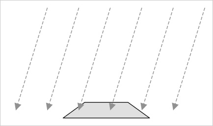
Figure 7-20 shows the way in which a directional light shines on objects rendered within a 3D scene. Note that the light has direction but does not have a position: the rays shown are all parallel and do not converge on any specific location.
The explanations we have looked at for each light revolve to a significant degree around determining whether each triangle in a rendered object is facing toward or away from a light. Triangles that are at the appropriate angle relative to the light will be illuminated brightly, whereas triangles facing away from the light will become darker or not be illuminated at all.
How does XNA tell whether a triangle is facing toward a light or not? There's nothing magical about this; in fact, the answer is rather basic: we have to tell XNA the direction in which each triangle is facing.
We do this just once when we create our object. When the object is rotating or moving in the game world, XNA will use this information and apply all the object transformations to the direction in which the triangle is facing, just as it does to the position of the vertices. The object lighting will therefore be automatically and dynamically calculated as each object or light moves within the scene.
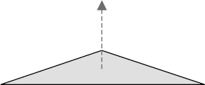
To tell XNA the direction in which each triangle is facing, we provide a Vector3 value known as a normal. A normal describes a line that is pointing in a direction perpendicular to the front of the triangle. Figure 7-21 shows a single triangle with its normal. The triangle itself is completely flat with its surface pointing directly upward. The normal, which is represented by a dashed arrow, therefore points upward, too.
In Figure 7-22, a solid shape is shown with its normals. Each side of the cube faces in a different direction, and once again dashed arrows are used to indicate the direction of the normal from each side.

To describe each normal, we use a different type of vertex object: VertexPositionNormalTexture. In addition to the Position and TextureCoordinate vectors that we explored already, this object contains an additional vector called Normal. This vector allows the three different values (for the x, y, and z axes) to describe the distance along each axis that would need to be travelled to move along the line of the normal.
For the triangles on top of the cube whose faces point directly upward, the normal vector would be (0, 1, 0). This vector shows that to travel along the line of the normal, we would move zero units along the x and z axes, and 1 unit along the positive y axis; in other words, we would move directly upward. The opposite face that points downward would have a normal vector of (0, - 1, 0). Moving in the direction of this vector would move us along the negative y axis.
Similarly, the triangles on the right edge of the cube have a normal vector of (1, 0, 0), and the triangles at the back of the cube (facing away from us) have a normal vector of (0, 0, - 1).
We need to provide these normal vectors to XNA for it to use when our object is being rendered. We only need to provide the vectors for when the object is in its default untransformed position. As the object is rotated within the scene, XNA will recalculate its resulting normal vectors automatically.
Notice that the normals we have discussed all have a length of 1 unit. This is important because XNA takes the normal length into account when performing its lighting calculations, and normal vectors that are longer or shorter than this might cause the reflected light to become brighter or darker. Vectors with a length of 1 unit are known as normalized vectors, whereas those with longer or shorter lengths are unnormalized vectors.
Once XNA knows the direction each triangle is facing, it can work out whether they face toward or away from the scene's lights and so determine how much light to provide for the triangle.
Although working out normal vectors is easy when they are aligned directly along the x, y, or z axis, they can be much more difficult to work out in your head when the triangle faces in a direction away from these axes. Calculating the normals manually for these triangles would be both tedious and prone to errors.
Fortunately, we are using a computer (albeit one that fits in your pocket), so we can get it to calculate the normals for us automatically.
There are all sorts of mathematical operations that can be calculated on vectors (and there are lots of books and online references that will cover this subject in immense detail if you want to investigate it further) and we can use one of these called a cross product to calculate the normal for us.
We will now briefly look at the calculation performed by the cross product, to understand what it does. Don't worry if you find the arithmetic complex or off-putting, however, for as you will see in a moment, XNA has support for doing all this built in to its Vector3 structure, so we don't have to calculate any of this manually. The explanation here simply describes what is going on under the covers.
To perform a cross product calculation, we need to find two vectors that lay along the surface of our triangle. They are easy to calculate because we can simply find the difference in position between the vertices of the triangle. For the purposes of this example, we will call these vectors a and b.
Consider the triangle shown in Figure 7-23. It is oriented so that its surface points directly upward (to keep the example simple!) and has vertex coordinates as shown.

Note that the triangle vertices are, as always, defined in clockwise order. This is important to our calculation; if they were defined in counterclockwise order, the normal we calculate would be facing in the opposite direction (downward in this case).
To calculate the two vectors that we need, we subtract the coordinates of vertex 1 from vertex 2 for the first vector, and subtract the coordinates of vertex 0 from vertex 1 for the second vector, as follows:
As you can see, these do indeed represent the distances from each vertex to the next. To move from vertex 1 to vertex 2, we would need to move 1 unit along the x axis, 0 units on the y axis, and 2 units on the z axis. To move from vertex 0 to vertex 1, we would need to move 1 unit on the x axis, 0 units on the y axis and −2 units along the z axis.
To perform the cross product operation, we need to perform the following calculations on vectors a and b. These will produce the normal vector n:
n.x = (a.y × b.z) – (a.z × b.y)
n.y = (a.z × b.x) – (a.x × b.z)
n.z = (a.x × b.y) – (a.y × b.x)
Let's substitute in the values for our vectors and see the results:
n.x = (0 × −2) – (2 × 0) = 0 – 0 = 0
n.y = (2 × 1) – (1 × −2) = 2 – −2 = 4
n.z = (1 × 0) – (0 × 1) = 0 – 0 = 0
The resulting vector n is therefore calculated as (0, 4, 0). This does indeed describe a line in the positive y axis, directly upward, exactly as we had hoped. The same calculation can be performed for any triangle regardless of its vertex locations.
So having seen what the cross product calculation actually does, let's make things a little simpler and take a look at how XNA can do this work for us. We still need to calculate the vectors a and b, but XNA will allow us to simply subtract one vertex position from another to calculate these. With the a and b vectors prepared, we can pass them to the static Vector3.Cross function, and it will return the normal. The code required to perform all of this is shown in Listing 7-14, which uses the same triangle as we used for our manual calculations.
Example 7.14. Calculating the normal for a triangle
// Create three vertices for our triangle
        Vector3 vertex0 = new Vector3(-1, 0, 1);
        Vector3 vertex1 = new Vector3(0, 0, −1);
        Vector3 vertex2 = new Vector3(1, 0, 1);

        // Calculate the a and b vectors by subtracting the vertices from one another
        Vector3 vectora = vertex2 - vertex1;
        Vector3 vectorb = vertex1 - vertex0;

        // Calculate the normal as the cross product of the two vectors
        Vector3 normal = Vector3.Cross(vectora, vectorb);

        // Display the normal to the debug window
        System.Diagnostics.Debug.WriteLine(normal.ToString());
Hopefully that should be a bit easier to understand! The output that is displayed by the code is the vector (0, 4, 0), exactly as with our manual calculations.
The normal vector we have calculated is not normalized, however; its length is 4 rather than 1. XNA's Vector3 structure has a Normalize method that we can call to easily normalize the value however, so we can just let XNA do it for us. The code shown in Listing 7-15 can be added after the call to Vector3.Cross from Listing 7-14 to normalize the vector.
The resulting normalized vector is (0, 1, 0)—a unit-length vector pointing directly upward. Perfect.
We will look at implementing all this in our program code in the section entitled "Programmatic Calculation of Normals," coming up shortly.
We have so far considered normals as applying to each face in our 3D object. In actual fact, it is not the faces that we apply normals to but the individual vertices that form the face. It is the vertices for which XNA calculates the color based on its lighting equations, and it then applies this to the whole triangle by interpolating the colors between the vertices just as we have manually interpolated colors ourselves by providing vertex colors.
This gives us an opportunity to perform a very useful lighting trick. We can provide different normals for the vertices of a single triangle. XNA will then consider each vertex of the triangle to be facing in a different direction and will interpolate the light directions across the surface of the triangle.
Consider the triangles in Figure 7-24. They are shown as thick lines, representing the triangles viewed edge-on. The long dashed arrows show the normals that have been applied for each of the vertices within the triangles. Note that for each triangle, the normals are pointing in different directions (they point slightly away from one another).
The shorter dashed arrows show the effective normals within the interior of the triangles due to interpolation. They smoothly transition from one normal to the next, giving the impression that the surface of the object when viewed face on is perfectly smooth, whereas in fact it is created from just five flat faces.

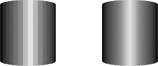
An example of normal interpolation in practice can be seen in Figure 7-25. The two images shown are both of the same cylinder, rendered using a number of flat surfaces. The individual surfaces can be clearly seen in the image on the left, which uses the same normals for all vertices within each face. On the right, the vertex normals are modified so that they differ from one side of the face to the other (exactly as we did in Figure 12-20). Note that the appearance of this cylinder is entirely smooth, even though it is formed from the exact same faces as the image on the left.
So that's the theory; now let's take a look at how we implement lighting in our game code. All the code in this section can be found in the Lighting example project that accompanies this chapter. A screenshot from the project is shown in Figure 7-26.

The first thing that is needed is to tell the BasicEffect object that we want to use lighting. Without this, all light features will be disabled and ignored, as has been the case in our example projects up until now.
Lighting is enabled by simply setting the LightingEnabled property to true when initializing the effect, as shown in Listing 7-16.
Lighting can, of course, be disabled by setting this back to false. This property can be updated anywhere within your game; it isn't restricted just to the Initialize function.
Once the lighting system has been switched on, the next step is to configure the lights. We have three directional lights at our disposal, exposed via the DirectionalLight0, DirectionalLight1, and DirectionalLight2 properties of the BasicEffect object. Each of these lights has the following properties that can be used to configure its behavior:
DiffuseColor: the diffuse color of the light. Defaults to white.Direction: aVector3structure indicating the direction in which the light is pointing. Defaults to (0, −1, 0), straight downward.Enabled: a bool indicating whether this light is switched on or off.SpecularColor: the specular color of the light. Defaults to black to disable specular lighting.
Note
All the light colors are represented as Vector3 structures. Remember that you can convert a Color to a Vector3 by calling its ToVector3 method.
The default configuration of the lights is for light 0 to be enabled and the other two lights to be disabled. As the lights point downward by default, this configuration creates an effect similar to the sun shining from directly overhead.
Updating the light settings is very easy because the parameters can be freely updated. To change a light's direction or its colors, or to switch it on and off, simply set the properties as required before rendering your objects.
The code in Listing 7-17 configures light 0 so that it is directed along the negative z axis. As the user's viewpoint is also looking along the negative z axis in our examples so far, this configuration results in the light illuminating the objects from the camera position.
Example 7.17. Configuring a white light to shine along the negative z axis
_effect.DirectionalLight0.Enabled = true;
        _effect.DirectionalLight0.Direction = new Vector3(0, 0, −1);
        _effect.DirectionalLight0.DiffuseColor = Color.White.ToVector3();
For the light itself, this code is all that is required to light up the objects within our scene. However, we haven't done anything to set the normals for our objects yet. Continuing to use the cube from our previous examples, we first modify the class to use the VertexPositionNormalTexture structure for its vertices. After setting the vertex positions as we always have, we now need to set the normal for each vertex. For a cube, the normals all point directly along the x, y, or z axis and so it is easy to set these up manually. Listing 7-18 shows the beginning of the code to perform this task, taken from the Lighting project's CubeObject class.
Example 7.18. Setting the cube's vertex normals
// Set the vertex normals
        i = 0;
        // Front face...
        _vertices[i++].Normal = new Vector3(0, 0, 1);
        _vertices[i++].Normal = new Vector3(0, 0, 1);
        _vertices[i++].Normal = new Vector3(0, 0, 1);
        _vertices[i++].Normal = new Vector3(0, 0, 1);
        _vertices[i++].Normal = new Vector3(0, 0, 1);
        _vertices[i++].Normal = new Vector3(0, 0, 1);
        // Back face...
        _vertices[i++].Normal = new Vector3(0, 0, −1);
        _vertices[i++].Normal = new Vector3(0, 0, −1);
        _vertices[i++].Normal = new Vector3(0, 0, −1);
        _vertices[i++].Normal = new Vector3(0, 0, −1);
        _vertices[i++].Normal = new Vector3(0, 0, −1);
        _vertices[i++].Normal = new Vector3(0, 0, −1);
        // ... and so on for the remaining faces ...
The cube's class is otherwise unchanged. Running the project displays a cube as shown in Figure 7-27. You can see that each face of the cube has its own color, determined by the light calculation that we have already explored.
Try experimenting with the light and material colors to see how they interact. The light color is set in the project's Initialize function (refer to Listing 7-17), whereas the object material is set against each individual object in its ObjectColor property. Thecube in the example project is added by the ResetGame function, and its color can be modified here.
As additional lights are enabled, XNA has additional work to do to calculate the light for each vertex within the rendered objects. For this reason it is important to disable lights when they are not required. Lighting is a relatively inexpensive calculation, so feel free to get your lights set up exactly how you need them for your game.
To use an ambient light, simply set the BasicEffect.AmbientLight property to the required color. All the objects rendered will take the ambient light into account.
Specular lighting is calculated both from the specular color of the active lights and from the specular material color. As the material colors are specific to each object, we will create new properties in the game framework's MatrixObjectBase class to support specular color for each individual object.
The new properties, SpecularColor (of type Color) and SpecularPower (of type float), mirror the properties within the BasicEffect that control the specular material. These can then be set within each object to control its specular lighting settings.
To apply the specular lighting, the MatrixObjectBase.PrepareEffect is modified to pass the object's values into the BasicEffect object's SpecularColor and SpecularPower properties.
Specular light generally looks at its best when it is white. By all means, experiment with colored specular light, but the effects might not always be natural-looking.
Figure 7-28 shows another cube with a white specular light and a specular power of 10. You can enable this in the example project by uncommenting the lines in ResetGame that set the two new specular lighting properties. Notice how shiny the cube looks compared with the one without specular lighting. One of the reasons for this shininess is that specular light affects each vertex differently, even if all the vertices of a face point in exactly the same direction. This effect results in a much more dynamic appearance on the rendered objects.

Try experimenting with the specular power and see the results. As the power value increases into the tens and hundreds, the cube starts to reflect specular light only when its faces get closer and closer toward the light source as the specular effect becomes more and more tightly focused.
There is one additional BasicEffect property that has an effect on specular lighting: PreferPerPixelLighting. This property defaults to false, which results in the specular component of the lighting model being calculated for each vertex, as we have already discussed. On objects that have large triangles (and therefore have areas of the object where there are no vertices nearby), this can result in some visual artifacts that can detract from the otherwise very attractive looking specular lighting.
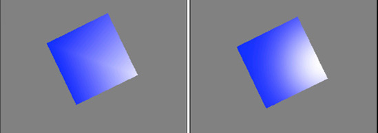
The first of these problems can be seen in the left image of Figure 7-29. The image shows a cube that is facing nearly directly toward the camera and the light source, but is slightly rotated so that the rightmost corner is the only one that is reflecting the specular light. As you can see, the light has a very angular look caused by the fact that only four vertices are being used to display the entire face of the cube. The interpolation is inaccurate due to this small number of color points.
The image on the right is of the exact same object and lighting configuration, except that PreferPerPixelLighting has been switched on. This property instructs XNA to calculate the specular lighting for each individual pixel that it renders, rather than just for the vertices. As will be clearly seen, the reflection looks much better: the angular lines have all disappeared, leaving a perfect round highlight in its place.
The second problem with specular lighting also occurs on objects with large triangles, but primarily affects specular light that is very tightly focused. Figure 7-30 shows two images of a cube that is directly facing toward the camera and the light source. The specular power has been set to 1000 for a very focused effect. Because the effect is so small, it doesn't reach any of the vertices at all. As a result, the specular light has no impact on the face. On the right is the same scene with per pixel lighting enabled. As each pixel then has its specular light individually calculated, the specular light effect clearly appears within the face.
Of course, as you might expect, there is a downside to per pixel lighting. Because the specular component needs to be calculated for each individual pixel as opposed to each vertex, it has a much higher processing requirement. Consider the cubes in Figure 7-30: the visible face consists of more than 30,000 pixels, as compared with only 6 vertices.
Per pixel lighting should therefore be used sparingly. If you have an object that is not using specular light, has no large faces, has a low specular power, or doesn't exhibit either of the problems discussed here, you will probably find a performance benefit from leaving it disabled. Experiment and find which setting provides the best balance between appearance and performance for your game.
The emissive light for rendered objects is also most usefully set for each individual object, so we will add a new property for this to the MatrixObjectBase class just as we did for the specular material color.
The EmissiveColor property (of type Color) can then be set within each object to control its emissive lighting settings and is applied in the MatrixObjectBase.PrepareEffect, which passes its value into the BasicEffect object's EmissiveColor property.
The lighting properties of the BasicEffect object give you a great deal of freedom to set up your lighting system in whatever way you want, but XNA has one additional feature that you might find useful in your games: the standard lighting rig.
I will allow Shawn Hargreaves, one of the Microsoft's XNA Framework developers, to explain with the following text from his blog (which, incidentally, is a fantastically useful resource for XNA programming and can be found at http://blogs.msdn.com/b/shawnhar/):
Many years ago photographers discovered that a single light was not enough to make their subjects look good. Instead, they use three.
The key light is the brightest, and provides the main illumination and shadows. This will typically be positioned to match a real light source such as an overhead lamp, a window, or the sun for an outdoor scene.
The fill light is dimmer, and usually angled at 90 degrees to the key. This is used to soften the shadows, adding shading and definition to areas that would otherwise be solid black.
Finally, the back light is positioned behind the character, facing toward the camera. This illuminates only the silhouette edges, helping the character stand out against the background.
Because this is potentially a very useful light configuration, it can be applied to your 3D game world by simply calling the BasicEffect.EnableDefaultLighting function. In practice, it might provide a useful set of lights, it might provide a useful basis but require a little subsequent modification, or it might not be suitable for your game at all. Give it a try and see what kind of results it provides; you might just like it.
Earlier in this section, we explored the calculations required to automatically calculate the normals for a triangle within a 3D object. As a final lighting-related addition to the game framework, let's add a function that will calculate the normals automatically.
This will be relatively basic, and will operate within the following restrictions:
It will only generate normals that are the same for all vertices of a triangle, so no smoothing using normal interpolation will be supported.
It will assume that each vertex will be either used only once or that all of its uses will have the same vertex normal. The code could potentially be enhanced to average out multiple uses of the same vertex, but this enhancement is left as an exercise for the reader. When we begin importing geometry in the next chapter, you will see that this might not be as valuable an enhancement as it currently appears.
It will support only triangle lists.
As we have two different ways of rendering triangles (a simple list of triangles or using vertex indices), we will create two corresponding functions that process data in these two formats. To reduce the amount of code, we will set the two functions up so that one simply calls into the other, allowing all the calculation to be put into just a single function.
The easiest way to implement this efficient code approach is to get the version that takes a simple list of triangles (without vertex indices) to build a corresponding index array. Once this is done, the vertices and the fabricated indices can be passed into the other function to calculate on its behalf.
Generating indices for an unindexed triangle list is very simple: each triangle is formed from the next three vertices in the list, so the indices are just a sequence of incremental numbers. The first triangle is formed from indices 0, 1, and 2; the second triangle from indices 3, 4, and 5; the third from indices 6, 7, and 8; and so on.
The code for the function that handles unindexed vertices, named CalculateVertexNormals and added to the MatrixObjectBase class, can be seen in Listing 7-19. It creates an array for the indices whose length is equal to the number of vertices. The array is then filled with sequential numbers starting from 0, and the vertices and constructed indices array are passed into a second overload of the same function to actually generate the normals, which we will examine in a moment.
Example 7.19. Generating indices for an unindexed triangle list
public void CalculateVertexNormals(VertexPositionNormalTexture[] vertices)
    {
        short[] indices;
        short i;

        // Build an array that allows us to treat the vertices as if they were indexed.
        // As the triangles are drawn sequentially, the indexes are actually just
        // an increasing sequence of numbers: the first triangle is formed from
        // vertices 0, 1 and 2, the second triangle from vertices 3, 4 and 5, etc.

        // First create the array with an element for each vertex
        indices = new short[vertices.Length];

        // Then set the elements within the array so that each contains
        // the next sequential vertex index
        for (i = 0; i < indices.Length; i++)
        {
            indices[i] = i;
        }

        // Finally delegate to the other overload to do the work
        CalculateVertexNormals(vertices, indices);
    }
The second overload of the function accepts two parameters: the vertex array and the index array. This version of the function would be used directly if you are working with indexed vertices, or will otherwise be called from the code in Listing 7-19 if the vertices are unindexed.
The second overload works through the vertices in the array, using the indices to determine which vertices are used to form each triangle within the object. Once the vertices of each triangle have been determined, their vectors are calculated and stored in the va and vb variables. Their cross product is then calculated in order to determine the triangle's normal, and the resulting vector is normalized. The normal vector is then written into all three of the vertices that formed the triangle. This is all exactly as per the processes we discussed in the "Calculating Normals" section earlier in this chapter.
Note that as we are updating the vertex array that was passed in as a parameter; there is no need to return anything from this function. The normals will be written "in place" into the existing vertices.
The code to calculate the normals is shown in Listing 7-20.
Example 7.20. Calculating the normals for an indexed triangle list
public void CalculateVertexNormals(VertexPositionNormalTexture[] vertices,
                                                                        short[] indices)
    {
        // Vectors to describe the relationships between the vertices of the triangle
        // being processed
        Vector3 vectora;
        Vector3 vectorb;
        // The resulting normal vector
        Vector3 normal;

        // Loop for each triangle (each triangle uses three indices)
        for (int index = 0; index < indices.Length; index += 3)
        {
            // Create the a and b vectors from the vertex positions
            // First the a vector from vertices 2 and 1
            vectora = vertices[index + 2].Position - vertices[index + 1].Position;
            // Next the b vector from vertices 1 and 0
            vectorb = vertices[index + 1].Position - vertices[index + 0].Position;

            // Calculate the normal as the cross product of the two vectors
            normal = Vector3.Cross(vectora, vectorb);

            // Normalize the normal
            normal.Normalize();

            // Write the normal back into all three of the triangle vertices
            vertices[index].Normal = normal;
            vertices[index+1].Normal = normal;
            vertices[index+2].Normal = normal;
        }
    }
This function can simply be called after the vertex positions for an object have been calculated. If you look at the CubeObject class in the Lighting example project, you will find that this can be used in place of the code that manually provides the normals. Try commenting out all the BuildVertices code that sets the vertex normals (from the "Set the vertex normals" comment on to the end of the function) and instead enable the call to CalculateVertexNormals. The end result is identical, but with a lot less code and a lot less effort.
Right at the start of this chapter we looked at the perspective projection matrix, and we have used this for all the subsequent exploration of 3D graphics. XNA offers another projection matrix that can be useful in certain game environments, however, called an orthographic projection.
Whereas the perspective projection causes objects farther away from the camera to become smaller, an orthographic projection does not: distant objects appear at exactly the same size as near objects. This is clearly an unrealistic representation of the real world and unsuitable for any game that tries to present a lifelike approximation of a 3D environment, but it does have two specific uses.
The first of these uses is for isometric 3D games. They are generally tile-based games viewed such that the camera is rotated around and elevated from its default position. Isometric viewpoints were common in pseudo-3D games before hardware acceleration become popular. Some famous games that have used this style of 3D graphics include Q*bert, Zaxxon, Knight Lore, Marble Madness, Populous, and (more recently) Civilization III and Diablo II. Isometric games are less common these days, but do still make occasional appearances, particularly as role playing and strategy games.
The second thing that orthographic projections are useful for is creating a pixel-aligned coordinate system. Clearly with perspective projections, moving an object one unit along the x or y axis might cause it to move a different number of physical pixels along that axis, depending on how near or far the object is from the camera. Because distance makes no difference in orthographic projections, a coordinate system can be set up that exactly matches the pixels on the screen, making precise pixel-based movement much easier.
Despite their different appearance, all other aspects of 3D rendering that we have explored still hold true with orthographic projection: hidden surfaces will still be removed, objects will still be lit, and transformations and rotations will still operate exactly as with perspective projection (though rotations can look a little strange without perspective: the brain thinks they are distorting and stretching because no equivalent transformation exists in the real world).
The shape of an orthographic viewing frustum is simply a cuboid area, such as the one shown in Figure 7-31.
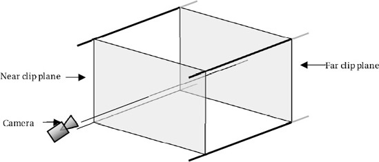
Just as with a perspective projection, we still have a near and far clip plane, and objects that are rendered will still be checked to ensure that they fall within this region. Despite objects not growing or shrinking as their depth changes within a scene, the depth buffer is still used and will ensure that objects with a higher z value will appear in front objects with a lower z value.
The reason why depth has no effect on the object size is that objects at the far clip plane occupy exactly the same proportion of the plane as objects on the near clip plane. If you look back at Figure 7-2, you will see two objects, one near and one far, contained within a perspective viewing frustum, and then in Figure 7-3 the projected outcome on the screen of those two shapes. Let's repeat these with an orthographic viewing frustum. Figure 7-32 shows the objects within the frustum, one at the near clip plane and one at the far clip plane just as before.
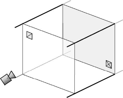
When these objects are transformed by the orthographic projection, they continue to appear at the same size, as can be seen in Figure 7-33. The proportion of the clip plane filled by the shapes is the same in both cases, and so they are not enlarged or shrunk at all.
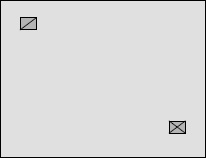
When we set up an orthographic projection, we simply tell it how many units we want it to use across the x and y axis. It will automatically stretch the rendered objects to fit within this defined set of coordinates. If the ratio of the axes does not match that of the screen, we can end up with objects becoming distorted as they are rendered. For example, if we used a range of −1 to +1 for both the x and y axes and displayed it on a 480 × 800 pixel screen, a 1-unit-square object would appear with a width of 240 pixels and a height of 400 pixels. It is clearly not square! For this reason, we generally still use the aspect ratio in our own calculations when setting the orthographic scale.
There is no need for a viewing angle to be specified for this projection because the angle is always parallel.
Just as XNA provided a useful function for creating projection matrices, so it provides another for orthographic projections—two, in fact, as you will see.
The first of these functions is the static Matrix.CreateOrthographic function. This expects the following four parameters:
width: the number of units to display across the projection. The center point will always be 0, so providing a width of 4 will result in a frustum that extends from −2 to +2 across the x axis.height: the number of units to display vertically for the projection. Just as with thewidth, the center point will always be 0.zNearPlane: the near clipping plane distance.zFarPlane: the far clipping plane distance.
Tip
Because distance has no effect on the sizing of objects, it is quite acceptable to set a near clipping plane with a negative distance, allowing objects that are effectively behind the camera to still be rendered. This configuration allows a coordinate system to be created where the value 0 is the center of all the 3D axes, which can simplify the object positional calculations.
Listing 7-21 shows an example orthographic projection matrix being created. Its vertical size is set at 16 units, and the horizontal size is calculated from the aspect ratio to display the appropriate amount to keep the coordinate system square.
Example 7.21. Calculating the normals for an indexed triangle list
// Calculate the screen aspect ratio
        float aspectRatio =
                     (float)GraphicsDevice.Viewport.Width / GraphicsDevice.Viewport.Height;
        // Create a projection matrix
        Matrix projection = Matrix.CreateOrthographic(16 * aspectRatio, 16, 0, 100.0f);
Let's take a look at a couple of applications of orthographic projection.
To obtain an isometric projection, we simply need to set the orthographic projection up as described and then rotate the camera so that it looks upon the scene from an angle, instead of straight on.
The effects of this camera rotation can be seen in Figure 7-34. The two images both display a unit-size cube with an orthographic projection. On the left, the camera is looking directly along the negative z axis, so only the front face of the cube can be seen. On the right, the camera has been moved so that it looks from the point (1, 1, 1) toward the origin point (0, 0, 0). As a result, the cube is now seen with its corner facing toward the camera. Note that the cube's front face (lit in medium gray) is now appearing at the bottom left of the cube; this should help you to visualize how the camera position has moved.

The code required to set the camera into this position is shown in Listing 7-22. This replaces the previous calculation of the view matrix in the game's Initialize function.
Example 7.22. Setting the camera position for an isometric projection
// Calculate a view matrix (where we are looking from and to) for isometric projection
      Matrix view = Matrix.CreateLookAt(new Vector3(1, 1, 1), Vector3.Zero, Vector3.Up);
With the camera so positioned, the world axes are shifted so that they are no longer aligned with the screen axis. Moving an object along the positive x axis will now cause it to move to the right and down on the screen. Moving an object along the positive z axis will cause it to move left and down on the screen, and the positive y axis will move up on the screen.
These positional effects can be seen in Figure 7-35. The cube labeled A is at position (0, 0, 0), the cube labeled B is at position (0, 1, 0), the cube labeled C is at position (0, 0, 1), and the cube labeled D is at position (2, 0, 0).

An example of using an isometric projection can be seen in the Isometric project accompanying this chapter. It sets up a grid of unit-size cubes along the x and z planes, and then scales them along the y axis to make them increase and decrease in height. An image from the project can be seen in Figure 7-36.
Using an isometric view of an orthographic projection will be useful in only a minority of games, but for those that do need it, XNA's rich 3D features create a powerful environment for displaying such graphical environments.
We can also use orthographic projections to align the coordinate system exactly to the pixels on the screen. This is generally useful only for 2D rendering, and in many cases will be more easily achieved by simply using XNA's sprite technology instead. As you have seen by now, however, there are features that the 3D rendering environment offers that sprites cannot achieve, such as powerful matrix-based positioning and flexible lighting.
To set up a pixel-aligned projection, we simply need to provide the actual viewport width and height when creating the matrix, as shown in Listing 7-23. Given a width of 480 and a height of 800, this configuration will create a coordinate system ranging from position (−240, −400) in the screen's bottom-left corner to position (240, 400) in its top-right corner.
Example 7.23. Creating a pixel-aligned orthographic projection matrix
// Create a pixel-aligned orthographic projection
        Matrix projection = Matrix.CreateOrthographic(GraphicsDevice.Viewport.Width,
                                                GraphicsDevice.Viewport.Height, 0, 100);
This works fine, but has put the origin (0, 0) coordinate in the center of the screen. Normally when working with 2D coordinate systems (such as the one used by XNA's sprites), the origin is in the top-left corner, and the positive y axis points toward the bottom of the screen. We can replicate this same system by using a different projection matrix creation function: CreateOrthographicOffCenter.
This function expects six parameters to be passed, as follows and in this order:
left: the coordinate to use to represent the left edge of the screenright: the coordinate for the right edge of the screenbottom: the coordinate for the bottom edge of the screentop: the coordinate for the top edge of the screenzNearPlane: the near clipping plane distancezFarPlane: the far clipping plane distance
Any values can be passed for the left, right, bottom, and top coordinates, so we can set the left and top values to be zero, and the right and bottom to be the viewport width and height, respectively. Listing 7-24 shows an example of setting the projection up in this way.
Example 7.24. Creating an off-center pixel-aligned orthographic projection matrix
// Create a pixel-aligned orthographic projection with its origin in the top-left
        // of the screen.
        Matrix projection = Matrix.CreateOrthographicOffCenter
                                                (0, GraphicsDevice.Viewport.Width,
                                                 GraphicsDevice.Viewport.Height, 0,
                                                 −100, 100);
If you wanted to put the origin (0, 0) coordinate to the bottom left instead, simply swap the bottom and top parameters and the whole display will flip vertically to achieve this.
Moving out of the realm of flat 2D graphics and into the depths of 3D is undeniably a big step. All sorts of additional challenges appear both in terms of code complexity and graphical modeling. XNA does provide a sound and flexible technology base to build on, and the rewards of 3D game programming can be great for players and developers alike.
Once you are happy and comfortable with the concepts and the code that we have discussed in this chapter, the next chapter will introduce you to a number of additional techniques that you can use in XNA to help bring your games to life.