5. Introducing 123D Design for iPad
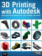
123D Design for iPad is a free application available on the Apple App Store (see Figure 5.1). It’s a great way to dive into design using the iPad’s great touch interface.

When you first start 123D Design, you might be presented with a brief overview of the menus. If you swipe to the left through the overview, then you’ll presented with a menu of choices along the left side, as shown in Figure 5.2.
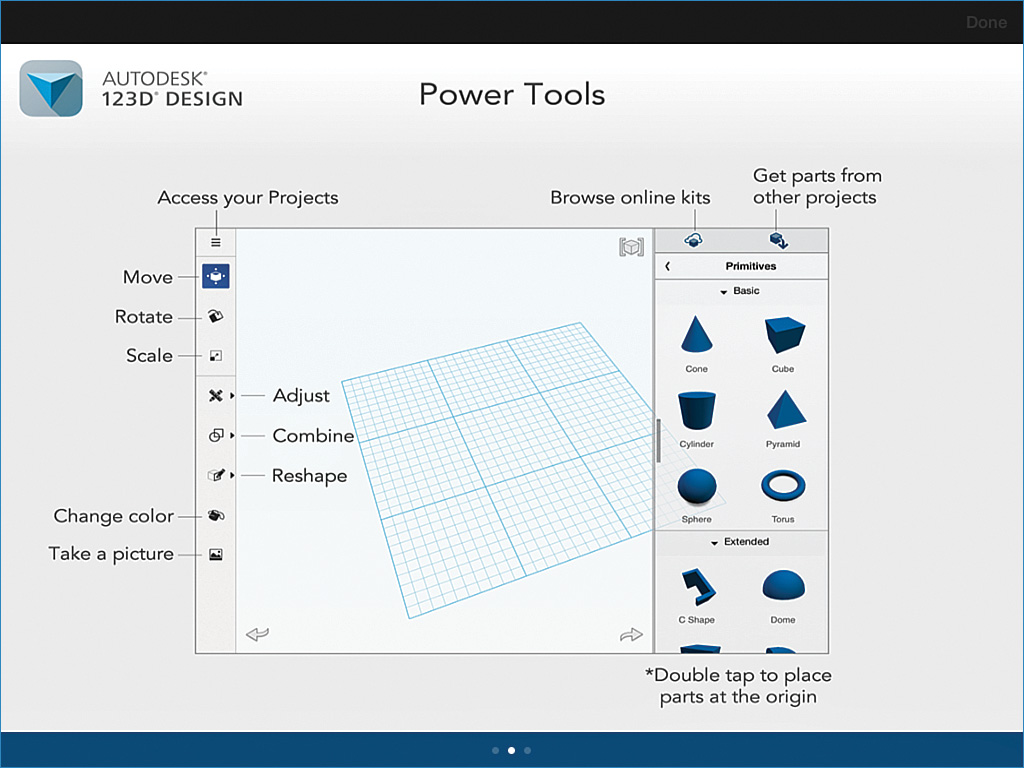
The application comes bundled with a large array of sample designs and many parts you can incorporate into your own designs—everything from robots to battleships and parts of everything in between. You can find these designs in the Examples tab (see Figure 5.3) and various parts and objects in the Parts Library.
Note
Like other Autodesk applications, 123D Design for iPad works better if you have an Autodesk account (it’s free to create one) so you can store and/or share your designs online. The account also makes it easier to move your designs from the iPad to the desktop application version of 123D Design because your designs will be available via the My Projects tab within both applications.
![]() A free online Autodesk account can be created at http://www.123dapp.com/. It takes only a minute, and you can sign in with any of the common social media logins or with just your email address.
A free online Autodesk account can be created at http://www.123dapp.com/. It takes only a minute, and you can sign in with any of the common social media logins or with just your email address.
123D Design Interface
Let’s take a tour of the interface to get familiar with it.
![]() In Chapter 6, “123D Design Exercises for iPad,” we go through some design exercises.
In Chapter 6, “123D Design Exercises for iPad,” we go through some design exercises.
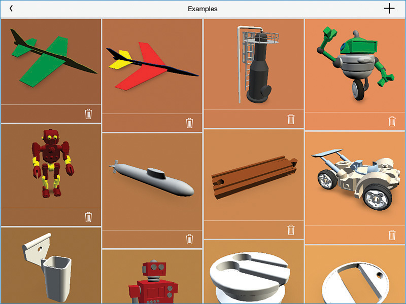
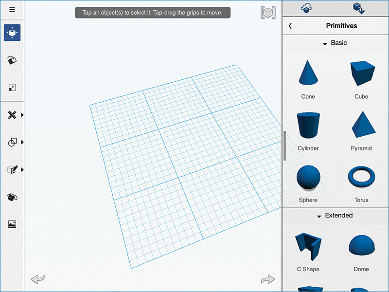
Selecting the New option from the upper-left menu takes you to the empty workspace, ready to begin your design work, as shown in Figure 5.4.
On the right side is a menu of parts you can use in your design. These parts make starting with a basic shape or part and then resizing or reshaping it to your liking much easier. It also makes adding other parts to it easy.
Primitives Parts
The first category of parts is called Primitives (see Figure 5.5). It is organized into a number of subcategories. Basic primitives consist of the basic building blocks you can use to build almost anything. These include spheres, cones, cubes, and cylinders. The Extended subcategory holds more complex versions or compilations of the basic primitives.
You can swipe right-to-left on the border of the Primitives library panel to drag it out for full-screen viewing of the parts library (see Figure 5.6).
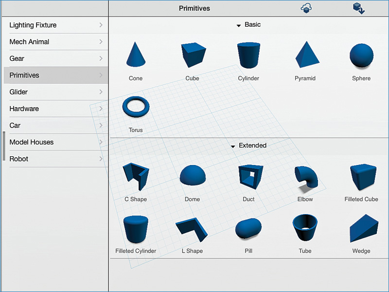
The two icons at the upper right of the Library pane access the Parts Kit Library (via the Internet) and insert one of your existing project designs into the current one. Tap the icons a second time to return to the Primitives menu.
Parts Kit Library
The Parts Kit Library contains hundreds of additional parts and designs you can access with an Autodesk account (see Figure 5.7). You simply browse through the selection and tap on the part you want to add, and it begins to download. You then can position it on the workspace.

Tip
Some objects might require a Premium membership to download them. Unfortunately, there is no indication on the model of whether it is free or part of the premium membership.
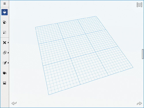
The left menu contains three primary object controls:
![]() Move
Move
![]() Rotate
Rotate
![]() Scale
Scale
These controls enable you to adjust your object with the arrows (called grips) that appear after the object has been selected by tapping on it (see Figure 5.8). You need to tap on an arrow and (without lifting) drag your finger in the chosen direction to move, scale, or rotate. Tap and then drag in the desired direction.

Tip
The grip arrows might not always be showing both ways depending on the orientation of your object, but they work in both directions.
If you tap and drag your finger on a space not touching your object, you’ll rotate the view or camera angle of the workspace. This is useful because you’ll want to inspect your object from all angles. If you pinch and zoom your fingers, you move the virtual camera closer or farther away from your object and the workspace.
Rotate Tool
The rotate tool shown in Figure 5.9 enables you to rotate the object within the workspace. This is useful for positioning multiple parts together at the correct angle(s).

If you get zoomed or rotated into a view that doesn’t help you or is confusing, you can always tap the Home View icon on the upper right of the workspace (it might be just to the left of the Parts Library window if it’s open). This effectively resets the camera’s view and centers your object in the workspace.
Scale Tool
The Scale tool shown in Figure 5.10 enables you to resize your object larger or smaller by tapping on it and then dragging the grips in the desired direction.

Below the three primary controls are three additional controls that have submenus that enable you to adjust, combine, and reshape your objects.
Adjust
The Adjust submenu contains the Snap, Align, and Information tools. The icon for this menu changes depending on which submenu tool is selected.
The Snap tool lets you tap on one object and have it snap (move) into place on another object depending on where you tapped. This can help with the assembly of separate parts and make it easy to move objects around by simply tapping on the faces you want to position together (see Figure 5.11).

You can use the Align tool shown in Figure 5.12 to assist in making multiple objects align along the same plane. When it’s selected, the Align tool adds handles around your objects, and you can tap on the top, middle, or bottom handle for each plane of alignment. Doing so moves each object to line up with the others along the selected plane.
The Information button, which is the final Adjust menu option (see Figure 5.13), is useful to display a visible ruler showing you the dimensions of the selected object.

Note
Displaying the ruler and part dimensions is important if you’re designing models that need to be used with existing parts where their size will matter when matching the parts together.
Combine Tools
Next we have the Combine tools. The icon for this menu changes depending on which submenu tool is selected. These controls enable you to combine two or more objects into one as well as subtract one or more objects from each other. These are what’s referred to as Boolean operations and are discussed in later chapters.
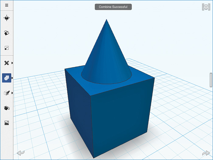
If you position two objects together, you can combine them using the Combine button (see Figure 5.14). This merges the two objects into a unified, single object.
Subtract Tool
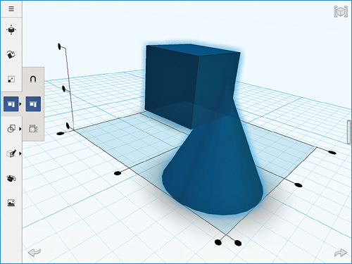
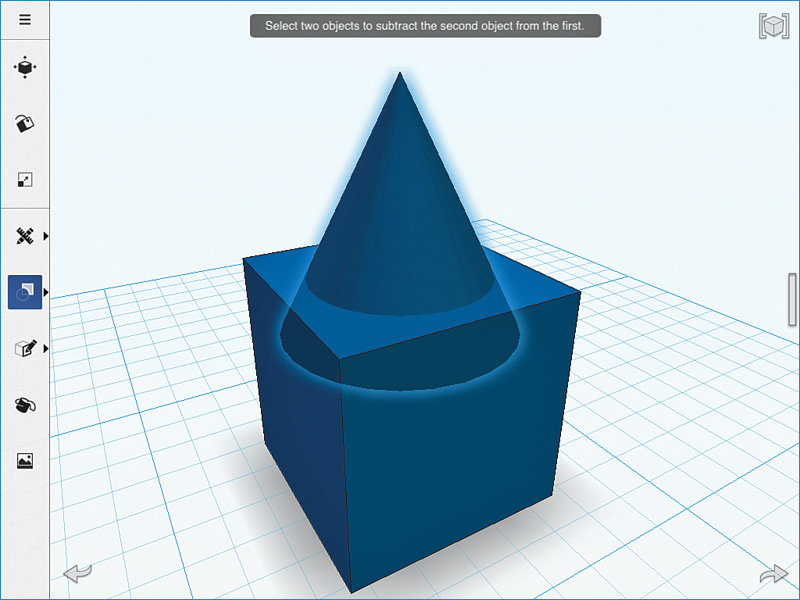
Like the Combine tool, the Subtract tool requires two objects that are intersecting each other. By using the Subtract tool, it prompts you to select the first object; then the second object you choose is subtracted from the first.
In Figure 5.15, a cube has a cone positioned near the top of the cube but is below the surface of the cube.
After subtracting, you can see the hole left behind where the cone was overlapping the cube (see Figure 5.16).

Reshape Tools
The Reshape tools are next. The icon for this menu changes depending on which submenu tool is selected. These controls enable you to modify the objects you’ve placed in a number of ways.
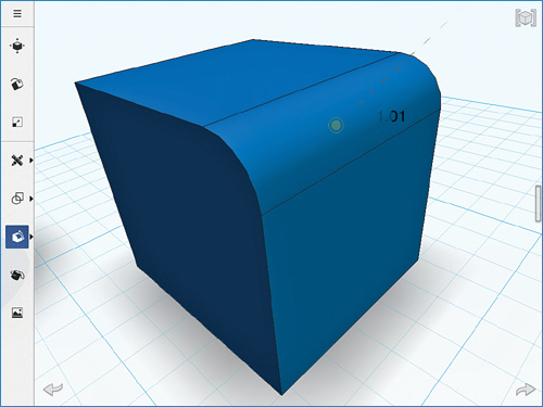
Chamfer (bevels edges) and Fillet (rounds corners) work similarly in that you select an edge of your object and can choose to apply a rounded fillet (see Figure 5.17) or a hard-edge chamfer (see Figure 5.18) to your object.

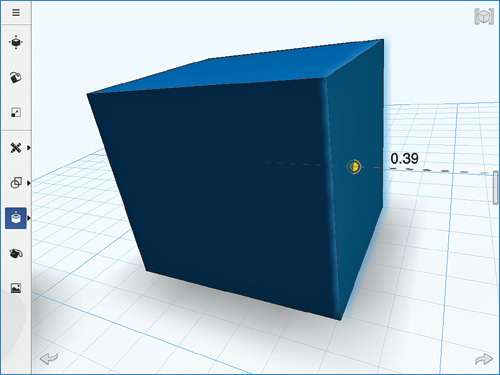
The Push In/Out tool allows you to select a face on an object and pull it out or push it in. This makes for easy resizing of a particular face. but only on an object. In Figure 5.19, a face of the cube has been selected and you are able to tap/drag the face away from the cube to lengthen or shorten that face.
Similarly, the hollow or shell tool allows you to select a face but instead of changing its length, it lets you create a hollow space with a varying thickness depending on your drag motion (see Figure 5.20).

FIGURE 5.20 Hollow an object by dragging the toggle to adjust the size of the void created by varying the thickness of the shell.
The color change tool is useful to make more complex shapes more visable, especially if there are multiple parts because you can make each object a different color (see Figure 5.21).

The last two options on the left menu are the Change Color and Take a Picture controls.
Take a Picture Option
The Take a Picture option enables you to remove your model from the workspace and lets you take a screenshot without the controls and other application elements in the shot. It’s a good way to show off your object when you’re done and to give others an idea of what the final object is supposed to look like when physically 3D printed.
Object Editing Tools
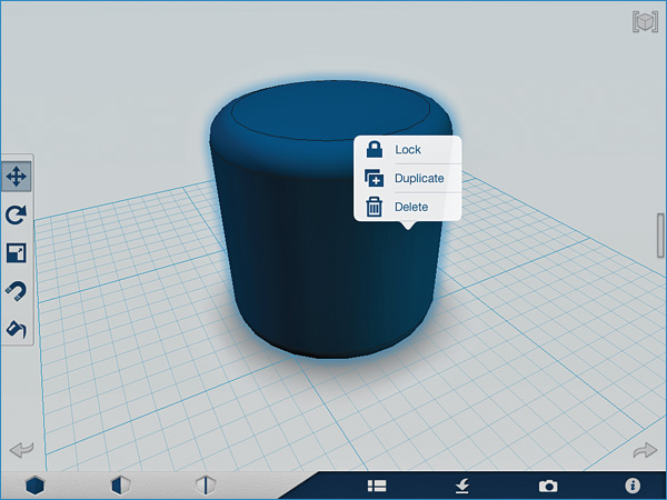
Tapping on an object and holding the tap for a second pops open the long hold menu (see Figure 5.22). This lets you lock the position and duplicate or delete the object you’ve tapped on.
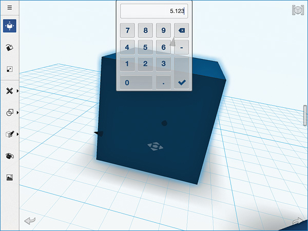
If you tap on the white arrow grip, you are presented with a pop-up numerical input (similar to a calculator) that enables you to enter a number for the amount you want to move or adjust your object without having to try to eyeball it using the touch interface. This allows you to properly position objects close to one another when knowing exactly how much your adjusting the object is important, as shown in Figure 5.23.
Project/File Menu Options
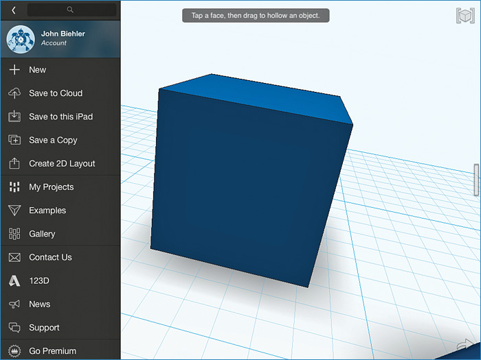
The Project/File menu shown in Figure 5.24 gives you a number of options to save your work and start a new project. The buttons for these options include the following:
![]() New—Start a new project. If you already have something on the go, it prompts you to save or discard your design before taking to you a blank workspace again.
New—Start a new project. If you already have something on the go, it prompts you to save or discard your design before taking to you a blank workspace again.
![]() Save to Cloud—Saves your project in the cloud.
Save to Cloud—Saves your project in the cloud.
![]() Save to this iPad—Saves your project locally on the iPad.
Save to this iPad—Saves your project locally on the iPad.
![]() Save a copy—Saves a copy of your project locally on the iPad.
Save a copy—Saves a copy of your project locally on the iPad.
![]() Create a 2D layout—Premium feature that creates a 2D layout for use with other Autodesk tools, which won’t be covered here.
Create a 2D layout—Premium feature that creates a 2D layout for use with other Autodesk tools, which won’t be covered here.
Projects and Galleries
The Projects and Galleries section of the menu (refer to Figure 5.24) give you access to the following options:
![]() My Projects—Displays all your currently saved projects on the iPad and in the cloud
My Projects—Displays all your currently saved projects on the iPad and in the cloud
![]() Examples—Displays all the models that Autodesk provides as examples, which can be great starting points to your projects
Examples—Displays all the models that Autodesk provides as examples, which can be great starting points to your projects
![]() Gallery—Displays all the publically shared projects in three different layouts (popular, featured, and recent)
Gallery—Displays all the publically shared projects in three different layouts (popular, featured, and recent)
Additional Support
The next section of this menu provides access to a variety of miscellaneous help and support options, including the following:
![]() Contact Us—Feedback email address for Autodesk
Contact Us—Feedback email address for Autodesk
![]() 123D—Displays other Autodesk products in the 123D suite
123D—Displays other Autodesk products in the 123D suite
![]() News—Provides the latest news from Autodesk 123D
News—Provides the latest news from Autodesk 123D
![]() Support—Takes you to a community support forum via your iPad’s web browser
Support—Takes you to a community support forum via your iPad’s web browser
![]() Go Premium—Displays your current account information and details about upgrading to Premium if you haven’t already
Go Premium—Displays your current account information and details about upgrading to Premium if you haven’t already
![]() Help—Displays simple onscreen help within 123D Design
Help—Displays simple onscreen help within 123D Design
![]() About—Displays legal and copyright information about the software and allows you to opt out of the collection of anonymous usage information for the application
About—Displays legal and copyright information about the software and allows you to opt out of the collection of anonymous usage information for the application
Tip
The About section can be used to turn off Autodesk’s ability to collect information about your usage of the software.
Saving to the Cloud
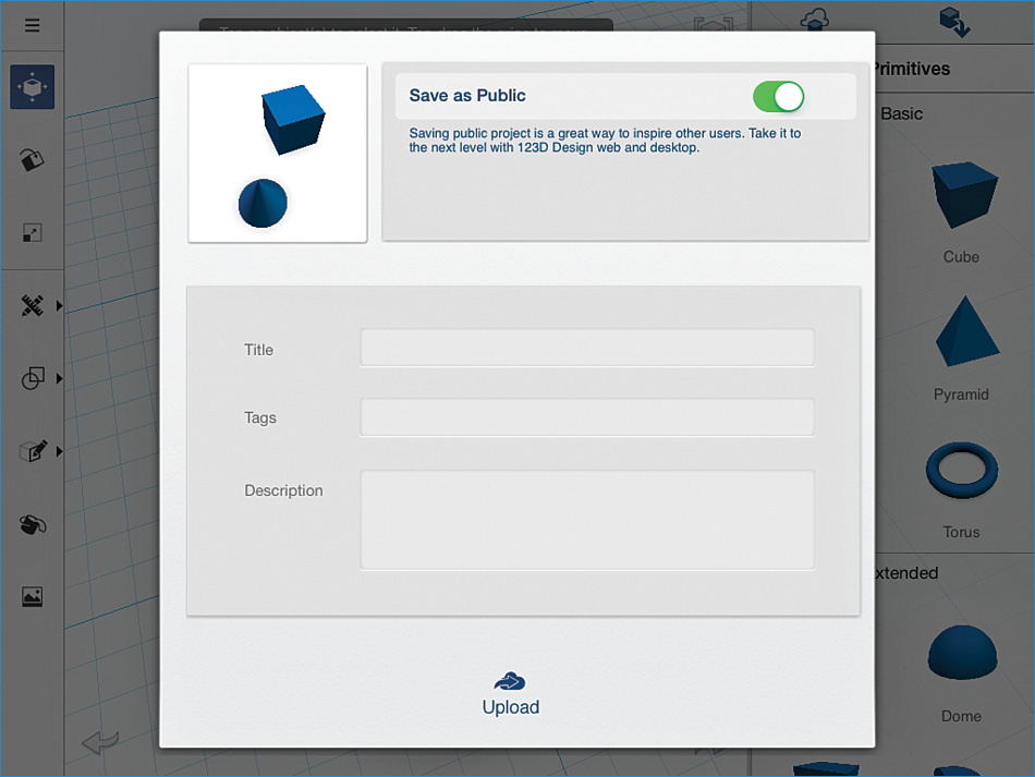
If you choose to save your object to the cloud (Figure 5.25), you’ll be given options to share it publically, as well as to give it a title, a description, and some tags that describe it to others when searching the public galleries. If you choose to not make it public, the tags and description become optional fields. Press the Upload button to save it to the cloud.
Camera View
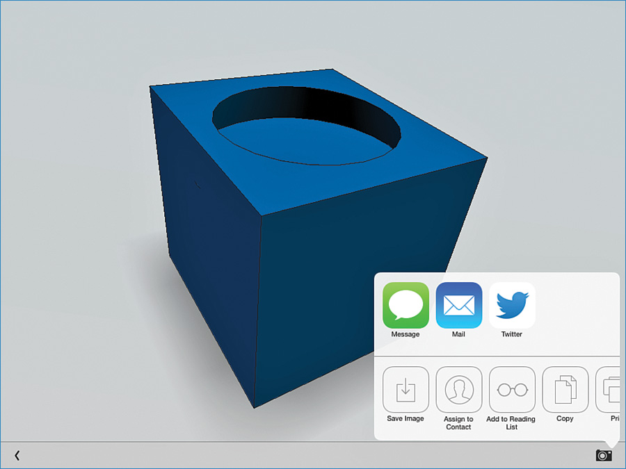
The Camera icon enables you to position your object onscreen without the workspace grid behind it so that you can share a screenshot via the iPad’s sharing menu (see Figure 5.26). This allows you to easily email, message, or tweet an image of your project from right inside 123D Design.
Summary
That wraps up our tour of 123D Design for iPad. In this chapter we’ve shown you most of the interface and control options you can use to create a model from basic primitive shapes. The Parts Library was also shown for starting with premade components that can be used as a starting point for your project.
In the next chapter, we walk through the steps to make a few different projects using what you’ve learned from this chapter.