11. Why and How to Use 3D Printing
There are three main uses for 3D printing in the design world. The first is to verify that designs are correct and will work. The second is for form and feel, while a third is for low-volume production.
Let’s start with design verification. You may well be asking yourself “Why do I need to 3D print prototypes? I thought modern software can analyze 3D models and can verify that things will work.” Hopefully you asked yourself quietly if other people are within listening range.
Note
A prototype is an early sample or model of an object or a concept that is created to use for testing. When testing of the prototype is successful, other forms are copied or developed from the prototype.
Yes, CAD software can analyze and simulate quite a bit, but as the title of the lead editorial in the Sept. 13, 2007 issue of Machine Design (http://machinedesign.com/archive/simulations-are-doomed-succeed) stated, “Simulations are doomed to succeed.”
The problem is that we tend to stop analyzing and simulating when we get what we think is a suitable answer, but simulations can be a classic example of garbage in, garbage out (GIGO). If we make the wrong assumptions when setting up the simulation and/or if we feed it incorrect values, then the simulation can give us what appears to be an acceptable result—but it won’t match the real world. There is also a strong tendency to think “It came out of a computer, therefore it is correct.”
What Can Possibly Go Wrong, Go Wrong, Go Wrong...
Let’s start with a couple of quick examples of humans trusting in the results from computer software.
The first example involves an Excel spreadsheet. The student assignment was to create macros within the spreadsheet so it would graph the deflection of a cantilever beam. For most of the students, it was their first encounter with programming, and many were struggling. When their spreadsheets finally stopped complaining about syntax errors, they handed them in. The problem was a common error—omitting one pair of parentheses. The macro would run, but you’d be surprised (and scared) by how many students thought a 4"×8" cantilever beam 12 feet long loaded with 1,000 pounds would deflect 34 million miles. This was a case of incorrect setup.
The next case comes from an exercise in professionally developed course material for a finite element analysis (FEA) session. Following step-by-step instructions, the students set up a vertical steel plate in the CAD software and “welded” an angle bracket to it, as shown in gray in Figure 11.1. They then constrained the bracket to the plate, applied a load to the end of the bracket, performed a stress analysis, and came to the conclusion that the bracket was strong enough.

The problem was that the instructions said to apply a load constraint between the plate and the entire flat face of one leg of the angle as though the bracket was glued in place, as shown in red in Figure 11.2.

In fact, however, it was attached by two fillet welds, one down each vertical edge of the bracket. Figure 11.3 shows how these welds had only a small fraction of the load-carrying area (shown by the two red strips) compared to the full-face–contact assumption. Therefore, in the real world the bracket would have failed at less than 5% of the specified load. This was a case of incorrect assumptions about how the constraints should be applied.

Admittedly, these two examples would not have been discovered by using a 3D printed model, but they do point out the hazards of relying too heavily on computer analyses.
Using 3D Prototypes to Verify Designs
Now let’s look at two cases where 3D-printed prototypes probably would have helped discover problems.
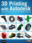
The first of these two cases involves a very complex 3D CAD model of a Harley chopper custom motorcycle. The model contained every nut, bolt, washer, and even all the balls in each ball bearing. The presenter was very proud of the model and the analyses. Figure 11.4 shows a simplified schematic of the geometry of the rear suspension.
You don’t need to look too hard to see that the geometry of the rear suspension was such that the rear spring was lifting the wheel up instead of pressing it down onto the road. When the first analysis failed, the presenter had simply reversed the sign of the applied force to get the simulation to succeed. This was a case of incorrect values being used. The bike was already under construction when I pointed out that it wouldn’t work, to which the presenter replied “Oh, poop,” or words to that effect. A 3D-printed model would have turned up the problem pretty quickly.
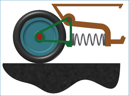
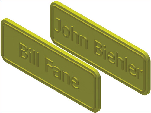
The second example is a more generic case that can point out the benefits of 3D-printed models. The problem is that the real world can be different from 3D CAD models in several significant ways. For example, Figure 11.5 shows a CAD model with the hole in the center of the wheel constrained to be concentric with the hole in the center of the bearing.

This looks good onscreen, but Figure 11.6 shows that in the real world if we don’t put a shaft between the wheel and the bearing, the wheel will fall off.
Even when we add the shaft to our CAD model, it will still be different from reality. In our CAD model the holes and the shaft remain perfectly concentric, but in the real world everything shifts off-center a bit by the clearances that are required for assembly and running. The red areas in Figure 11.7 indicate this.

A 3D-printed prototype can help determine whether these anomalies are likely to cause problems. Bob Newhart did a great comedy routine about a supermarket manager ordering new grocery carts. He wanted 7 that pulled to the left, 5 that pulled right, and 12 that went “thunka-thunka-thunka”.
When relatively simple examples such as these can get messed up, it sort of makes you wonder about the validity of extremely complex analyses such as weather and financial forecasting, doesn’t it? Ah, yes, but the answer came out of a computer....
Note
3D printing can greatly reduce the cost of prototypes. A few years back the padlock on my boat trailer hitch cost more than $5,000 and took two weeks to produce because it was the first handmade prototype of a product that eventually went into production and sold for about $5.00. Today, a 3D-printed prototype would cost a few dollars and take a few hours to be produced. Granted, it probably would not be strong enough to serve in the real world, but it would help to verify fit and function.
Manufacturing Small Quantities with 3D Printing
3D printing is also known as additive manufacturing, and as this terminology implies, it can be used for producing more than just prototypes. It can also be used for manufacturing low-volume quantities, where low volume might be 100 parts or less.
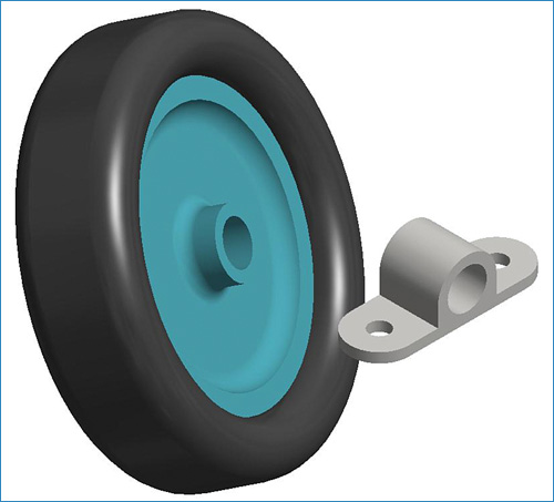
The most common forms of 3D printing use thermoplastics such as ABS and PVC, and so might be appropriate for producing small production quantities of plastic parts such as specialized and even personalized novelty items. For example, Autodesk Inventor can create a 3D feature starting from a regular text object, and by changing the content of the text, you can update the model. How about personalized name plates, as shown in Figure 11.8?
Creating Metal Parts with 3D Printing
Okay, 3D printing can produce sample parts from plastic or other soft materials, but what if you need metal parts? You might want only one or two for prototype testing before committing a huge pile of money into molds for zinc or aluminum die castings, or perhaps you need only a few dozen production parts for a low-volume product.
No problem. The 3D-printed part can be used as the pattern for sand-cast metal parts. Figure 11.9 shows the basic cope and drag made using the 3D-printed part as the pattern. Now, all the foundry needs to do is to add the sprues, gates, runners, and vents as appropriate, although these could even be added to a derived variant of the basic part so they would already be 3D printed as part of the pattern.

FIGURE 11.9 A plastic 3D print of the rocker arm is used as a pattern to produce the cope and drag for a sand casting in metal.
3D-printed parts can also be used as the pattern for investment casting. Simply dip the part in plaster and then melt or dissolve the pattern as per the standard investment casting process.
Allowing for Shrinkage
One significant point to remember is that almost all materials shrink as they solidify during the casting process, so the part you 3D print to be a casting pattern will have to be larger than the final part by the shrinkage ratio. This can easily be accomplished by using Autodesk Inventor’s derived part functionality whereby a new part is created by deriving it from an existing part file.
Tip
Of particular interest in this process is the fact that a scale factor can be set. Aluminum, for example, typically shrinks about 10% depending on the particular alloy and the temperature, so a derived part would use a scale factor of 1.1 to produce a casting pattern that will produce a finished cast part of the correct size.
Using 3D Printing for Large Parts
Speaking of size, 3D printers—especially lower-priced units—typically do not print large parts. There are two workarounds for this problem.
First, a scale model might suffice. I have seen a model of a two-story house scaled down by 1:48 (1/4" = 1' 0", commonly called quarter-inch scale). It was a great demonstration model to show prospective buyers before the house was built, and it could help the architect find any anomalies in the design.
Second, larger parts can be printed in smaller sections and then glued together. I have seen a full-size model of a chopper motorcycle (no, not the one referred to earlier; this one was correct) and one of an aircraft jet engine made this way.
Summary
No matter how powerful computer analysis is these days, it’s still a very good idea to make a physical sample as a final check. 3D printing can be a fast, economical method for producing such prototypes. It can also be used for producing very small runs of production parts.