
A valuable tool for selecting, linking, and organizing scene objects is the Schematic View window. This window offers a 1,000-foot view of the objects in your scene. From this whole scene perspective, you can find the exact item you seek.
The Schematic View window shows all objects as simple nodes and uses arrows to show relationships between objects. This structure makes the Schematic View window the easiest place to establish links and to wire parameters. You can also use this view to quickly see all the instances of an object.
A great way to organize and select objects is by using the Schematic View window. Every object in the Schematic View is displayed as a labeled rectangular box. These boxes, or nodes, are connected to show the relationships among them. You can rearrange them and save the customized views for later access.
The Schematic View menu options enable you to manage several different views. The Graph Editors
Every time the Graph Editors
Tip
You can open any saved Schematic View window (or a new Schematic View window) within a viewport by right-clicking the viewport title, choosing Views
The Schematic View window includes several common interface elements including menus, toolbar buttons, and a right-click quadmenu. Just like the main interface, you can access the commands in many ways.
The Schematic View window includes menus at the top of its interface, including Edit, Select, List Views, Layout, Options, Display, and View.
The Edit menu includes commands to Connect (C) and Unlink Selected object nodes. It also includes a Delete command, which deletes an object from the viewports as well as from the object node. The Edit menu includes commands to Assign Controllers, Wire Parameters, and a command to open the Object Properties dialog box.
Note
Many of the keyboard shortcuts for the Schematic View window are the same as those in the main interface. If you enable the Keyboard Shortcut Override Toggle, then you can use the Schematic View keyboard shortcuts.
The Select menu includes commands for accessing the Select tool (S or Q); selecting All (Ctrl+A), None (Ctrl+D), and Invert (Ctrl+I); selecting (Ctrl+C) and deselecting children; and commands to synch the selected nodes in the Schematic View with the scene (Select From Scene) and vice versa (Select to Scene).
The List Views menu determines what is shown in the Schematic View. Options include All Relationships, Selected Relationships, All Instances, Selected Instances, Show Occurrences, and All Animated Controllers. Many of these options are also available in the Display Floater.
The Layout menu includes various options for controlling how the nodes are arranged. The Align submenu lets you align selected nodes to the Left, Right, Top, Bottom, Center Horizontal, or Center Vertical. You can also Arrange Children, or Arrange Selected. The Free Selected (Alt+S) and Free All (Alt+F) commands remove nodes from being auto arranged. With the Layout menu, you can also Shrink Selected, Unshrink Selected, Unshrink All, and Toggle Shrink (Ctrl+S).
The Options menu lets you select the Always Arrange option and view mode (either Hierarchy and Reference modes). You can also select the Move Children (Alt+C) option and open the Schematic View Preferences (P) dialog box.
The Display menu provides access to the Display Floater. The Display Floater (D) command opens the Display floater, which can be used to select the types of nodes to display. You also can hide and unhide nodes and expand or collapse the selected node.
The View menu includes commands for selecting the Pan (Ctrl+P), Zoom (Alt+Z), and Zoom Region (Ctrl+W)tools. You also can access the Zoom Extents (Alt+Ctrl+Z), Zoom Extents Selected (Z), and Pan to Selected commands. The View menu also includes options to Show/Hide Grid (G), Show/Hide Background, and Refresh View (Ctrl+U).
You can also select most of these commands from the toolbar. Many of the toolbar buttons are toggle switches that enable and disable certain viewing modes. The background of these toggle buttons is highlighted yellow when selected. You'll also find some buttons along the bottom of the window. All Schematic View icon buttons are shown in Table 24.1 and are described in the following sections.
Note
The Schematic View toolbar buttons are permanently docked to the interface and cannot be removed.
Table 24.1. Schematic View Toolbar Buttons
Toolbar Button | Name | Description |
|---|---|---|
Display Floater | Opens the Display Floater, where you can toggle which items are displayed or hidden. | |
Select (S) | Toggles selection mode on, where nodes can be selected by clicking. | |
Connect (C) | Enables you to create links between objects in the Schematic View window; also used to copy modifiers and materials between objects. | |
Unlink Selected | Destroys the link between the selected object and its parent. | |
Delete Objects | Deletes the selected object in both the Schematic View and in the viewports. | |
Hierarchy Mode | Displays all child objects indented under their parents. | |
References Mode | Displays all object references and instances. This mode displays all materials and modifiers associated with the objects. | |
Always Arrange | Causes all nodes to be automatically arranged in a hierarchy or in references mode, and disables moving of individual nodes. | |
Arrange Children | Automatically rearranges the children of the selected object nodes. | |
Arrange Selected | Automatically rearranges the selected object nodes. | |
Free All | Allows all objects to be freely moved without being automatically arranged. | |
Free Selected | Allows selected objects to be freely moved without being automatically arranged. | |
Move Children | Causes children to move along with their parent node. | |
Expand Selected | Reveals all nodes below the selected node. | |
Collapse Selected | Rolls up all nodes below the selected node. | |
Preferences | Opens the Schematic View Preferences dialog box. | |
View Name field | Allows you to name the current display. Named displays show up underneath the Graph Editors | |
Bookmark Name | Marks a selection of nodes to which you can return later. | |
Go to Bookmark | Zooms and pans to the selected bookmarked objects. | |
Delete Bookmark | Removes the bookmark from the Bookmark selection list. |
As you navigate the Schematic View window, you can save specific views as bookmarks by typing an identifying name in the Bookmark drop-down list. To recall these views later, select them from the drop-down list and click the Go to Bookmark icon in the Schematic View toolbar. Bookmarks can be deleted with the Delete Bookmark button.
Note
Most of the menu commands and toolbar buttons are available in a pop-up menu that you can access by right-clicking in the Schematic View window.
As the number of nodes increases, it can become tricky to locate and see the correct node to work with. Along the bottom edge of the Schematic View window are several navigation buttons that work similarly to the Viewport Navigation Control buttons. Using these buttons, you can pan, zoom, and zoom to the extents of all nodes. These buttons are described in Table 24.2.
The Schematic View navigation buttons can also be accessed from within the View menu. These menu commands include Pan Tool (Ctrl+P), Zoom Tool (Alt+Z), Zoom Region Tool (Ctrl+W), Zoom Extents (Alt+Ctrl+Z), Zoom Extents Selected (Z), and Pan to Selected.
Tip
You can also navigate the Schematic View window using the mouse and its scroll wheel. Scrubbing the mouse wheel zooms in and out of the window in steps. Holding down the Ctrl key and dragging with the scroll wheel button zooms smoothly in and out of the window. Dragging the scroll wheel pans within the window.
Table 24.2. Schematic View Navigation Buttons
Toolbar Button | Name | Description |
|---|---|---|
Zoom Selected Viewport Object | Zooms in on the nodes that correspond to the selected viewport objects. | |
Search Name field | Locates an object node when you type its name. | |
Pan | Moves the node view when you drag in the window. | |
Zoom | Zooms when you drag the mouse in the window. | |
Region Zoom | Zooms to an area selected when you drag an outline. | |
Zoom Extents | Increases the window view until all nodes are visible. | |
Zoom Extents Selected | Increases the window view until all selected nodes are visible. | |
Pan to Selected | Moves the node view at the current zoom level to the selected objects. |
Every object displayed in the scene has a node—a simple rectangular box that represents the object or attribute. Each node contains a label, and the color of the node depends on the node type.
Nodes have a color scheme to help identify them. The colors of various nodes are listed in Table 24.3.
Table 24.3. Schematic View Node Colors
Color | Name |
|---|---|
White | Selected node |
Blue | Geometry Object node |
Cyan | Shape Object node |
Yellow | Light Object node |
Dark Blue | Camera Object node |
Green | Helper Object node |
Purple | Space Warp Object node |
Goldenrod | Modifier node |
Dark Yellow | Base Object node |
Brown | Material node |
Dark Green | Map node |
Salmon | Controller node |
Magenta | Parameter Wires |
Note
If you don't like any of these colors, you can set the colors used in the Schematic View using the Colors panel of the Customize
When you click the Select (S) button, you enter select mode, which lets you select nodes within the Schematic View window by clicking the object node. You can select multiple objects by dragging an outline over them. Holding down the Ctrl key while clicking an object node selects or deselects it. Selected nodes are shown in white.
The Select menu includes several selection commands that enable you to quickly select (or deselect) many nodes, including Select All (Ctrl+A), Select None (Ctrl+D), Select Invert (Ctlr+I), Select Children (Ctrl+C), and Deselect Children.
If the Select
Tip
All animated objects have their node border drawn in red.
The Schematic View includes several options for arranging nodes. In the Options menu, you can toggle between Hierarchy and Reference modes. Hierarchy mode displays the nodes vertically with child objects indented under their parent. Reference mode displays the nodes horizontally allowing for plenty of room to display all the various reference nodes under each parent node. Figure 24.2 shows these modes side by side.
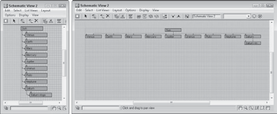
Figure 24.2. The Schematic View window can automatically arrange nodes in two different modes: Hierarchy and Reference.
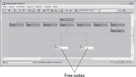
You can move nodes and rearrange them in any order. To move a node, simply click and drag it to a new location. When a node is dragged, all selected nodes move together, and any links follow the node movement. If a child node is moved, all remaining child nodes collapse together to maintain the specified arrangement mode. The moved node then becomes free, which is designated by an open rectangle on the left edge of the node. Figure 24.3 shows two nodes that were moved and thereby became free. The other children automatically moved closer together to close the gaps made by the moving nodes.
Using the Layout
If the Options
If your Schematic View window starts to get cluttered, you can always hide nodes to simplify the view. To hide a node, select the nodes to hide and use the Display
Note
If you hide a parent object, its children nodes are also hidden.
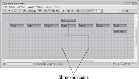
Another useful way to reduce clutter in the Schematic View window is with the Layout
Note
The Shrink commands work only when Layout
To delete a node, select the node and click the Delete Objects button on the Schematic View toolbar or press the Delete key. If several nodes are selected, they are all deleted. This deletes the object in the viewports also.
In the Schematic View window, you can rename objects quickly and conveniently. To rename an object, click a selected node and click again to highlight the text. When the text is highlighted, you can type the new name for the object. This works only for nodes that have a name, which includes materials.
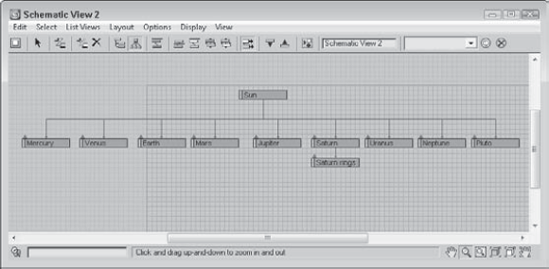
To practice moving nodes around, you'll order the solar system model. When Max places nodes in the Schematic View, it really doesn't follow any specific order, but you can move them as needed by hand.
To rearrange the solar system nodes, follow these steps.
Open the Ordered solar system.max file from the Chap 24 directory on the DVD.
This file includes several named spheres representing the solar system.
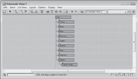
Select Graph Editors

All planets are displayed as blue nodes under the Sun object.
Select Options
Make sure that the Options
Select the Options
With the Move Children option enabled, the Saturn rings node moves with its parent.
Drag and drop the Pluto node beyond the Neptune node.
Select all the planet nodes, and choose Layout
Note
Although astronomers no longer classify Pluto as a planet, I doubt that this book is required reading for astronomers. I think we can get away with calling Pluto a planet.
Figure 24.5 shows the rearranged hierarchy with all the planets lined up in order.
Another key benefit of the Schematic View is to see the relationships between different objects. With the Schematic View open, you can quickly tell which objects are children and which are parents. You can also see which objects have modifiers and which have materials applied. You can get a wealth of knowledge from the Schematic View.
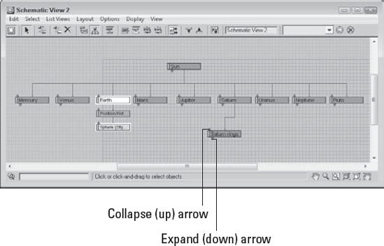
With all relationships enabled, the Schematic View becomes a mess. Luckily, you can control which Relationships and which Entities are displayed using the Display floater, shown in Figure 24.6.
The top section of the Display floater shows or hides relationships between nodes, which are displayed as lines. The relationships that you can control include Constraints, Controllers, Param Wires, Light Inclusion, and Modifiers. If you hold the mouse over these relationship lines, the details of the relationship are shown in the tooltip that appears.
Tip
For some relationships, you can double-click on the relationship line to open a dialog box where you can edit the relationship. For example, double-clicking on a Parameter Wire relationship line opens the Parameter Wiring dialog box.
The lower section of the Display Floater lets you show or hide entities that are displayed as nodes, including Base Objects, Modifier Stack, Materials, and Controllers. The P, R, and S buttons let you turn on Positional, Rotational, and Scale controllers. When a node has a relationship with another node, the right end of the node displays an arrow. Clicking this arrow toggles the relationship lines on and off.
The Expand button shows the actual nodes when enabled, but only an arrow that can be clicked on to access the nodes if disabled. The Focus button shows all related objects as colored nodes, and all other nodes are unshaded.
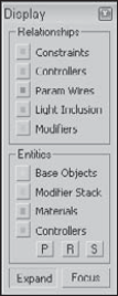
Figure 24.7 shows a Schematic View with the Base Objects and Controllers Entities selected in the Display floater. The Expand button is also disabled. This makes up and down arrows appear above each node. Clicking the up arrow collapses the node, rolling it up into its parent. Clicking the down arrow expands the node and displays the Base Object and Controller nodes for the node that you clicked on, such as the Earth node in Figure 24.7. You can also expand and collapse nodes with the Display
Hierarchical relationships are shown as lines that connect the nodes. Even if the nodes are moved, the lines follow as needed to show the relationship between the nodes.
To create a hierarchy, use the Edit
For linking nodes, the Connect button works the same way here as it does on the main toolbar—selecting the child node and dragging a line from the child node to its parent. You can even select multiple nodes and link them all at once.
The Edit
Before you can copy materials or modifiers between nodes, you need to make sure that they are visible. Material nodes and modifier nodes show up only if they are enabled in the Display floater. You can access this floater by clicking the Display floater button (or by pressing the D key).
To copy a material or modifier, select the material node for one object, click the Connect (C) button, and drag the material to another object node.
Note
In the Schematic View, materials can be copied only between objects—you cannot apply new materials from the Material Editor to Schematic View nodes.
When modifiers are copied between nodes, a dialog box appears, giving you the chance to Copy, Move, or Instance the modifier. You can also use the Schematic View window to reorder the Modifier Stack. Using the Connect tool, just drag the modifier node to the modifier node that you want to be beneath and the stack is reordered.
Note
You can learn more about applying modifiers and the Modifier Stack in Chapter 11, "Introducing Modifiers and Using the Modifier Stack."
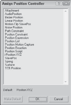
If controller nodes are visible, you can copy them to another node using the same technique used for materials and modifiers using the Connect (C) button. You can also assign a controller to an object node that doesn't have a controller using the Edit
Nodes can be wired using the Schematic View window. To wire parameters, just select the node that you want to wire and select Edit
Note
You can learn more about parameter wiring in Chapter 20, "Understanding Animation and Keyframe Basics."
Perhaps one of the greatest benefits of the Schematic View is its ability to link objects. This can be tricky in the viewports because some objects are small and hidden behind other items. The Schematic View with its nodes that are all the same size makes it easy, but only if the objects are named correctly.
To link a character model using the Schematic View, follow these steps:
Open the Futuristic man.max file from the Chap 24 directory on the DVD.
This file includes a simplified version of a futuristic man created by Viewpoint Datalabs with no links between the various parts.
Select Graph Editors
For this model, you want the pelvis to be the parent node.
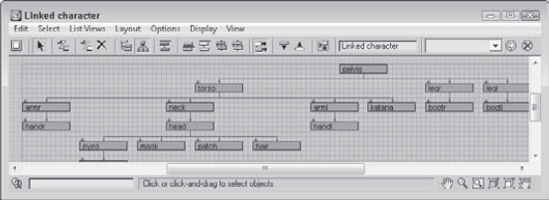
Click the Connect button on the toolbar (or press the C key), and drag from the handr node to the armr node to link the two nodes. Continue linking by connecting the following nodes: handl to arml, head to neck, pupil to eyes, bootr to legr, bootl to legl, and torso to pelvis.
Select the eyes, mask, patch, and hair nodes, and drag them all to the head node.
Finally, grab the armr, arml, neck, and katana nodes, and drag them to the torso node and the legr and legl nodes to the pelvis node.
This completes the hierarchy.
Note
Typically, when rigging characters, you want the pelvis to be the parent object because it is the center of most of the character movement.
Figure 24.9 shows the final geometry object nodes of the linked character. If you move the pelvis part in the viewports, all the parts move together.
The Preferences button opens the Schematic View Preferences dialog box, shown in Figure 24.10, where you can set which items are displayed or hidden, set up grids and background images, and specify how the Schematic View window looks.
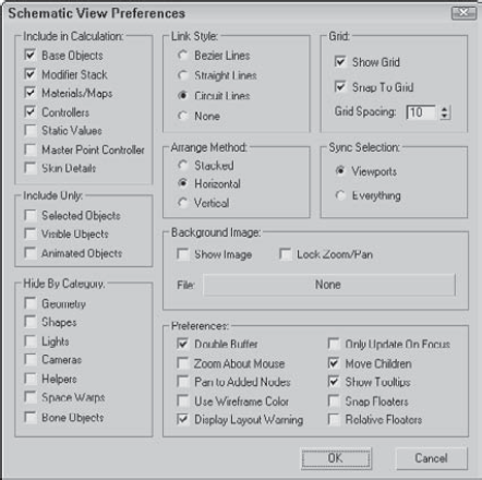
Figure 24.10. The Schematic View Preferences dialog box lets you customize many aspects of the Schematic View window.
When the Schematic View window is opened, Max traverses the entire hierarchy looking for objects and features that can be presented as nodes. If you have a complex scene and don't intend on using the Schematic View to see materials or modifiers, you can disable them in the Include in Calculation section of the Schematic View Preferences dialog box. This provides a way to simplify the data presented. With less data, locating and manipulating what you are looking for becomes easier.
The Include in Calculation section includes options for limiting the following:
Base Objects: The geometry type that makes up a node. The node is the named object, such as Earth; the Base Object is its primitive, such as Sphere (Object).
Modifier Stack: Identifies all nodes with modifiers applied.
Materials/Maps: Identifies all nodes with materials and maps applied.
Controllers: Identifies all nodes that have controllers applied.
Static Values: Displays unanimated parameter values.
Master Point Controller: Displays nodes for any subobject selections that include controllers.
Skin Details: Displays nodes for the modifiers and controllers that are used when the Skin modifier is applied to a bones system.
You can also limit the number of nodes by using the Include Only options. The Selected Objects option shows only the objects selected in the viewports. The nodes change as new objects are selected in the viewports. The Visible Objects option displays only the nodes for those objects that are not hidden in the viewports, and the Animated Objects option displays only the nodes of the objects that are animated.
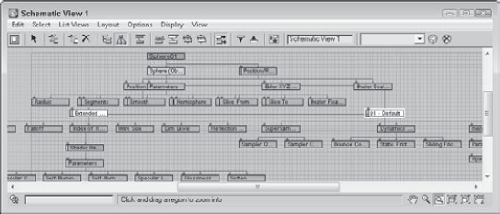
Object categories that can be hidden include Geometry, Shapes, Lights, Cameras, Helpers, Space Warps, and Bone Objects. Figure 24.11 shows a single sphere object in the Schematic View window with all the Include in Calculation options selected.
The Schematic View Preferences dialog box includes settings to Show Grid, Snap to Grid, and set Grid Spacing. The keyboard shortcut for toggling the grid on and off is G. Enabling the Snap to Grid option makes the nodes snap to the closest grid intersection. This helps keep the nodes aligned and looking neat.
The Background Image section of the Schematic View Preferences dialog box includes a File button that opens a file dialog box when clicked. Selecting an image file opens and displays the image as a background image. This is helpful as you arrange nodes. You need to select the Show Image option to see the background image, and the Lock Zoom/Pan option locks the nodes to the background image so zooming in on a set of nodes also zooms in on the background image.
Tip
One of the easiest ways to get a background image of a model to use in the Schematic View is to render a single frame and save it from the Rendered Frame Window to a location where you can reopen it as the Schematic View background. If you want to print the hierarchy, you can do a screen capture of the Schematic View window, but it would be nice to have a print feature added to the window.
In the Schematic View Preferences dialog box, you can select the style to use for relationship lines. The options include Bezier, Straight, Circuit, and None. When the Always Arrange, Arrange Children, or Arrange Selected options are used, you can select to have the nodes arranged Stacked, Horizontal, or Vertical. The Sync Selection options enable you to synch the selection between the Schematic View and the Viewports or between Everything. If the Everything option is selected, then not only are geometry objects in the viewports selected, but if a material is selected in the Schematic View, then the material is selected in the Material Editor also. Sync Selection Everything also affects the Modifier Stack, the Controller pane in the Display panel, and the Wiring Parameters dialog box.
The Schematic View Preferences dialog box also includes a Preferences section. These preference settings include Double Buffer, which enables a double-buffer display and helps improve the viewport update performance. The Zoom About Mouse Pointer preference enables zooming by using the scroll wheel on your mouse or by pressing the middle mouse button while holding down the Ctrl key. The Move Children option causes children nodes to move along with their parent. The Pan to Added Nodes preference automatically resizes and moves the nodes to enable you to view any additional nodes that have been added.
The Use Wireframe Color option changes the node colors to be the same as the viewport object color. The Display Layout Warning lets you disable the warning that appears every time you use the Always Arrange feature. The Only Update on Focus option causes the Schematic View to update only when the window is selected. Until then, any changes are not propagated to the window. This can be a timesaver when complex scenes require redraws.
The Show Tooltips option allows you to disable tooltips if you desire. Tooltips show in the Schematic View window when you hover the cursor over the top of a node. Tooltips can be handy if you've zoomed out so far that you can't read the node labels; just move the cursor over a node, and its label appears. The Snap Floater option enables the Display and List floaters to be snapped to the edge of the window for easy access, and the Relative Floaters option moves and resizes the floaters along with the Schematic View window.
You can position nodes anywhere within the Schematic View window. For example, you can position the nodes to look something like the shape of the model that you're linking. When positioning the different objects, having a background image is really handy.
To add a background image for the Schematic View, follow these steps:
Open the Futuristic man with background.max file in the Chap 24 directory on the DVD.
This file uses the same futuristic man model used in the preceding example.
With the Perspective viewport maximized, select Tools
The viewport image opens the Rendered Frame Window.
Click the Save Bitmap button in the upper-left corner. Save the image as Futuristic man–front view. Then close the Rendered Frame Window.
Select Graph Editors
Locate the saved image, and open it. Select the Show Image option in the Schematic View Preferences dialog box and click OK.
You can perform this step using the image file saved in the Chap 24 directory on the DVD, if you so choose.
Select the View
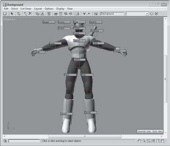
Before moving any of the nodes, enable the Lock Zoom/Pan option in the Schematic View Preferences dialog box so the image resizes with the nodes. Then, select each of the nodes, and drag them so that they are roughly positioned on top of the part that they represent. Start by moving the parent objects first, and then work to their children.
Figure 24.12 shows all the nodes aligned over their respective parts. From this arrangement, you can clearly see how the links are organized.
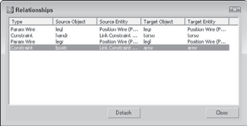
One of the last uses of the Schematic View is to list all nodes that have things in common. Using the List Views menu, you can select to see All Relationships, Selected Relationships, All Instances, Selected Instances, Show Occurrences, and All Animated Controllers.
The List Views
Tip
You can click each column head to sort the entries.
The List Views
Note
Another way to identify instances is to look for bold text in the node. All label text for all instanced nodes is displayed in bold.
If a node is selected and you want to see all other nodes that share the same type of relationship or that share a property, the List Views
Some tasks in the viewport, such as linking objects into a hierarchy, can be difficult. The Schematic View represents all data as simple rectangular nodes. These nodes make easy work of accomplishing a variety of tasks.
In this chapter, you've done the following:
Viewed all objects as nodes using the Schematic View window
Learned the Schematic View interface
Used the Schematic View window to select, delete, and copy objects, materials, and modifiers
Used the Schematic View to assign controllers and wire parameters
Set preferences for the Schematic View window
Listed views of nodes with common properties
In the next chapter, you learn more about features that enable deforming meshes, including the Paint Deformation tool and various modifiers that may be applied to mesh objects.