
Lights play an important part in the visual process. Have you ever looked at a blank page and been told it was a picture of a polar bear in a blizzard or looked at a completely black image and been told it was a rendering of a black spider crawling down a chimney covered in soot? The point of these two examples is that with too much or too little light, you really can't see anything.
Light in the 3D world figures into every rendering calculation, and 3D artists often struggle with the same problem of too much or too little light. This chapter covers creating and controlling lights in your scene.
Lighting plays a critical part of any Max scene. Understanding the basics of lighting can make a big difference in the overall feeling and mood of your rendered scenes. Most Max scenes typically use one of two types of lighting: natural light or artificial light. Natural light is used for outside scenes and uses the sun and moon for its light source. Artificial light is usually reserved for indoor scenes where light bulbs provide the light. However, when working with lights, you'll sometimes use natural light indoors, such as sunlight streaming through a window, or artificial light outdoors, such as a streetlight.
Natural light is best created using lights that have parallel light rays coming from a single direction: You can create this type of light using a Direct Light. The intensity of natural light is also dependent on the time, date, and location of the sun: You can control this intensity precisely using Max's Sunlight or Daylight systems.
The weather can also make a difference in the light color. In clear weather, the color of sunlight is pale yellow; in clouds, sunlight has a blue tint; and in dark, stormy weather, sunlight is dark gray. The colors of light at sunrise and sunset are more orange and red. Moonlight is typically white.
Artificial light is typically produced with multiple lights of lower intensity. The Omni light is usually a good choice for indoor lighting because it casts light rays in all directions from a single source. Standard white fluorescent lights usually have a light green or light blue tint.
When lighting a scene, not relying on a single light is best. A good lighting method includes one key light and several secondary lights.
A spotlight is good to use for the main key light. It should be positioned in front of and slightly above the subject, and it should usually be set to cast shadows, because it will be the main shadow-casting light in the scene.
The secondary lights fill in the lighting gaps and holes. You can position these at floor level on either side of the subject, with the intensity set at considerably less than the key light and set to cast no shadows. You can place one additional light behind the scene to backlight the subjects. This light should be very dim and also cast no shadows. From the user's perspective, all the objects in the scene will be illuminated, but the casual user will identify only the main spotlight as the light source, because it casts shadows.
Figure 19.1 shows the position of the lights on an elk model that are included in the standard lighting model using a key light, two secondary lights, and a backlight. This model works for most standard scenes, but if you want to highlight a specific object, additional lights are needed.
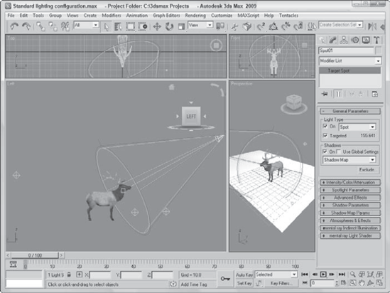
Figure 19.2 shows an elk model that was rendered using different levels of the standard lighting model. The upper-left image uses the default lighting with no lights. The upper-right image uses only the key light. This makes a shadow visible, but the details around the head are hard to define. The lower-left image includes the secondary lights, making the head details more easily visible and adding some highlights to the antlers. The bottom-right image includes the backlight, which highlights the back end of the model and casts a halo around the edges if viewed from the front.
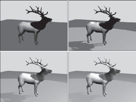
Figure 19.2. An elk model rendered using default lighting, a single key light, two secondary lights, and a backlight
The final type of light to keep in mind is ambient light. Ambient light is not from a direct source but is created by light that is deflected off walls and objects. It provides overall lighting to the entire scene and keeps shadows from becoming completely black. Global Lighting (including Ambient light) is set in the Environment panel.
Shadows are the areas behind an object where the light is obscured. Max supports several types of shadows, including Area Shadows, Shadow Maps, and Raytraced Shadows.
Area Shadows create shadows based on an area that casts a light. It doesn't require lots of memory and results in a soft shadow that is created from multiple light rays that blur the shadows. Shadow maps are actual bitmaps that the renderer produces and combines with the finished scene to produce an image. These maps can have different resolutions, but higher resolutions require more memory. Shadow maps typically create fairly realistic, softer shadows, but they don't support transparency.
Max calculates raytraced shadows by following the path of every light ray striking a scene. This process takes a significant amount of processing cycles but can produce very accurate, hard-edged shadows. Raytracing enables you to create shadows for objects that shadow maps can't, such as transparent glass. The Shadows drop-down list also includes an option called Advanced Raytraced Shadows, which uses memory more efficiently than the standard Raytraced Shadows. Another option is the mental ray Shadow Map.
Note
You can learn more about raytracing and mental ray in Chapter 46, "Raytracing and mental ray."
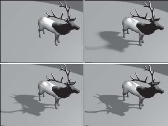
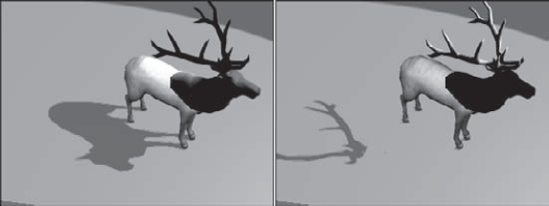
Figure 19.3 shows several images rendered with the different shadow types. The image in the upper left includes no shadows. The upper-right image uses Area Shadows. The lower-left image uses a Shadow Map, and the lower-right image uses Advanced Raytraced Shadows. The last two images took considerably longer to create. Viewpoint Datalabs created the elk model shown in this figure.
Max includes several different types of lights. The main difference in these types is how the light rays are cast into the scene. Light can come from the default lights that are present when no other user-created lights have been added to the scene. Light can also come from ambient light, which is light that bounces off other objects. Max includes several standard light objects that can be added where needed to a scene, including Omni, Direct, Spot, and skylights, each having its own characteristics. Max also includes a category of Photometric lights, which are based on real-world lights. Understanding these sources of light will help you know where to look to control the lighting.
So you get Max installed, and you eagerly start the application, throw some objects in a scene, and render it ...and you'll be disappointed in the output, because you forgot to put lights in the scene. Right? Wrong! Max is smart enough to place default lighting in the scene that does not have any light.
The default lighting disappears as soon as a light is created in a scene (even if the light is turned off). When all the lights in a scene are deleted, default lighting magically reappears. So you can always be sure that your objects are rendered using some sort of lighting. Default lighting actually consists of two lights: The first light is positioned above and to the left, and the bottom light is positioned below and to the right.
The Viewport Configuration dialog box has an option to enable default lighting for any viewport or set the default lighting to use only one light. You can open this dialog box by choosing Views
If you want to access the default lights in your scene, you can use the Create
Warning
The Create
Ambient light is general lighting that uniformly illuminates the entire scene. It is caused by light that bounces off other objects. Using the Environment dialog box, you can set the ambient light color. You can also set the default ambient light color in the Rendering panel of the Preference Settings dialog box. This is the darkest color that can appear in the scene, generally in the shadows.
In addition to these global ambient settings, each material can have an ambient color selected in the Material Editor.
Warning
Don't rely on ambient light to fill in unlit sections of your scene. If you use a heavy dose of ambient light instead of placing secondary lights, your scene objects appear flat, and you won't get the needed contrast to make your objects stand out.
Within the Create panel, the available lights are split into two subcategories: Standard and Photometric. Each subcategory has its own unique set of properties. The Standard light types include Omni, Spot (Target and Free) and Direct (Target and Free), Skylight, and two area lights (Spot and Omni) that work with mental ray.
The Omni light is like a light bulb: It casts light rays in all directions. The two default lights are Omni lights.
Spotlights are directional: They can be pointed and sized. The two spotlights available in Max are a Target Spot and a Free Spot. A Target Spot light consists of a light object and a target marker at which the spotlight points. A Free Spot light has no target, which enables it to be rotated in any direction using the Select and Rotate transform button. Spotlights always are displayed in the viewport as a cone with the light positioned at the cone apex.
Note
Both Target Spot and Target Direct lights are very similar in functionality to the Target Camera object, which you learn about in Chapter 18, "Configuring and Aiming Cameras."
Direct lights cast parallel light rays in a single direction, like the sun. Just like spotlights, direct lights come in two types: a Target Direct light and a Free Direct light. The position of the Target Direct light always points toward the target, which you can move within the scene using the Select and Move button. A Free Direct light can be rotated to determine where it points. Direct lights are always displayed in the viewport as cylinders.
The Skylight is like a controllable ambient light. You can move it about the scene just like the other lights, and you can select to use the Scene Environment settings or select a Sky Color.
The Area lights project light from a defined area instead of from a single point. This has the effect of casting light along a wider area with more cumulative intensity that a point light source. Area lights are supported only by the mental ray renderer. If you use the Scanline renderer, these lights behave like simple point lights.
The Area Omni light lets you set its shape as a Sphere or a Cylinder in the Area Light Parameters rollout. Area Spot lights can be set to be either Rectangular or Disc-shaped. Be aware that area lights can take significantly longer to render than point lights.
Note
For more details on the mental ray renderer, see Chapter 46, "Raytracing and mental ray."
The standard Max lights rely on parameters like Multiplier, Decay, and Attenuation, but the last time I was in the hardware store looking for a light bulb with a 2.5 Multiplier value, I was disappointed. Lights in the real world have their own set of measurements that define the type of light that is produced. Photometric lights are lights that are based on real-world light measurement values such as Intensity in Lumens and temperatures in degrees Kelvin.
If you select the Lights menu or the Lights category in the Create panel, you'll notice another subcategory called Photometric. Photometric lights are based on photometric values, which are the values of light energy. The lights found in this subcategory include Free and Target lights.
Note
The photometric lights in 3ds Max 2009 have been redesigned to consistent of only two different types: Free and Target. For each of these lights, you can select from a number of different light distribution models and shapes.
Note
The Photometric category also includes a mr Sky Portal option that is used to focus lights coming in from an external source. This feature is covered in Chapter 45, "Raytracing and mental ray."
To make choosing the right light easier, Max includes a Templates rollout for photometric lights that lets you set the configuration for a number of different common real-world lights, including 40, 60, 75, and 100W light bulbs, a number of Halogen spotlights, recessed lights, fluorescent lights, and even street and stadium lights.
Note
Whenever a photometric light is created, a warning dialog box appears informing you that it is recommended that the Logarithmic Exposure Control be enabled. It also offers you can option to enable this setting. You can learn more about this feature in Chapter 45, "Using Atmospheric and Render Effects."
Max, in its default setup, can create many different types of light. Each has different properties and features. To create a light, just select Create
Lights can be transformed just like other geometric objects. To transform a light, click one of the transformation buttons and then select and drag the light.
Target lights can have the light and the target transformed independently, or you can select both the light and target by clicking the line that connects them. Target lights can be rotated around the X and Y axes only if the light and target are selected together. A target light can spin about its local Z-axis even if the target isn't selected. Scaling a target light increases its cone or cylinder. Scaling a Target Direct light with only the light selected increases the diameter of the light's beam, but if the light and target are selected, then the diameter and distance are scaled.
An easy way to select or deselect the target is to right-click the light and choose Select Target from the pop-up menu. All transformations work on free lights.
Lights and shadows can be displayed in the viewports if you are using the Direct3D display driver. You can check to see if your video card supports interactive lights and shadows using the Help
If your graphics card supports viewport shading, you can enable viewport shading using the Viewport Lighting and Shadows
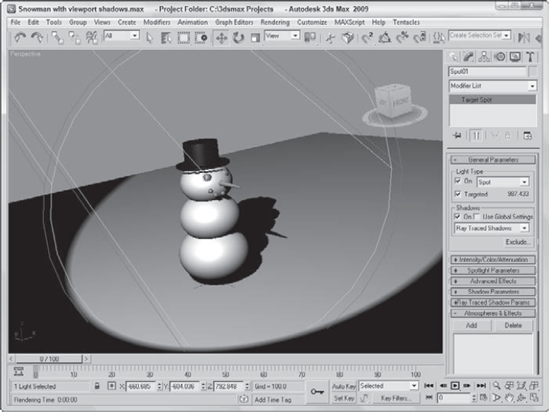
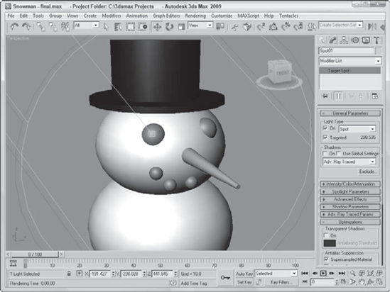
The Viewport Lighting and Shadows quadmenu also includes options to lock and unlock the selected light, commands to enable and disable shadows for the selected light, a command to select all lights displaying shadows and all lights displaying lighting, and options to auto display the selected lights and to display only the selected lights. Figure 19.4 shows a snowman with shadows enabled in the viewport.
The Tools
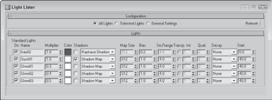
Figure 19.5. The Light Lister dialog box includes a comprehensive list of light settings in one place.
If the General Settings option is selected, then a separate rollout opens with all the typical settings, including Multiplier, Color, Shadows, Map Size, and so on. You can apply these changes to the Selected Lights or to All Lights. The Light Lister provides an easy way to change the parameters of many lights at once.
If either the All Lights option or the Selected Lights option is selected, then the parameters are listed in the Lights rollout. Using this rollout, you can change the settings for any of the listed lights that affect all lights. The Refresh button updates the Light Lister dialog box if a new light has been added to the scene or if any parameters have been altered in the Modify panel.
Note
If several lights are instanced, then only one of the instanced lights appears in the Light Lister dialog box, but each of the instanced lights can be selected from a drop-down list.
The Place Highlight feature enables you to control the position and orientation of a light in order to achieve a highlight in a precise location. To use this feature, you must select a light object in the scene and then choose Tools
Tip
If you click and drag on the object surface, then a small blue vector points from the surface of the object. The light is positioned inline with this vector when the mouse button is released. This is helpful when trying to precisely place a light.
You can use the Place Highlight feature to position a light for our snowman. To place a highlight, follow these steps:
Open the Snowman.max file from the Chap 19 directory on the DVD.
This file contains a simple snowman created using primitive objects.
Select the Create

To place the highlight so it shows the Snowman's face, select the spot light and then choose Tools
Figure 19.6 shows the results.
You can configure viewports to display the view from any light, with the exception of an Omni light. To do so, right-click the viewport title and then select Views and the light name at the top of the pop-up menu.
Note
The keyboard shortcut for making the active viewport a Light view is the $ (the dollar sign that appears above the 4) key. If more than one light exists, then the Select Light dialog box appears and lets you select which light to use. This can be used only on spot and direct lights.
When a viewport is changed to show a light view, the Viewport Navigation buttons in the lower-right corner of the screen change into Light Navigation controls. Table 19.1 describes these controls.
Note
Many of these controls are identical for viewports displaying lights or cameras.
If you hold down the Ctrl key while using the Light Hotspot or Falloff buttons, Max maintains the distance between the hotspot and falloff cones. Holding down the Alt key causes the size to change at a much slower rate. The Hotspot cone cannot grow any larger than the Falloff cone, but if you hold down the Shift key, then trying to make the size of the hotspot larger than the falloff causes both to increase, and vice versa.
Table 19.1. Light Navigation Control Buttons
Toolbar Button | Name | Description |
|---|---|---|
Dolly, Target, Both | Moves the light, its target, or both the light and its target closer to or farther away from the scene in the direction it is pointing. | |
Light Hotspot | Adjusts the angle of the light's hotspot, which is displayed as a blue cone. | |
Roll Light | Spins the light about its local Z-axis. | |
Zoom Extents All, Zoom Extents All Selected | Zooms in on all objects or the selected objects until they fill the viewport. | |
Light Falloff | Changes the angle of the light's falloff cone. | |
Truck Light | Moves the light perpendicular to the line of sight. | |
Orbit, Pan Light | The Orbit button rotates the light around the target, whereas the Pan Light button rotates the target around the light. | |
Min/Max Toggle | Makes the current viewport fill the screen. Clicking this button a second time returns the display to several viewports. |
You can constrain any light movements to a single axis by holding down the Shift key. The Ctrl key causes the movements to increase rapidly.
For Free lights, an invisible target is determined by the distance computed from the other light properties. You can use the Shift key to constrain rotations to be vertical or horizontal.
Note
You can undo changes in the normal viewports using the Views
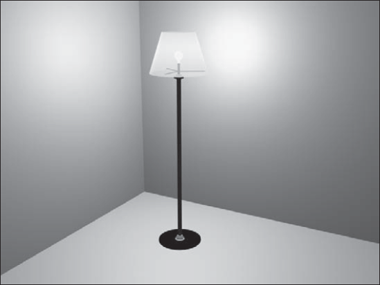
To practice using lights, you'll try to get a lamp model to work as it should.
To add a light to a lamp model, follow these steps:
Open the Lamp.max file from the Chap 19 directory on the DVD.
This file includes a lamp mesh surrounded by some plane objects used to create the walls and floor. The lamp model was created by Zygote Media. It looks like a standard living room lamp that you could buy in any department store.
Select the Create
Use the Select and Move transform button (W) to position the light object inside the lamp's light bulb.
The resulting image is shown in Figure 19.7. Notice that the light intensity is greater at places closer to the light.
Lights affect every object in a scene and can really make or break a rendered image, so it shouldn't be surprising that each light comes with many controls and parameters. Several different rollouts work with lights.
If you're looking for a light switch to turn lights on and off, look no further than the Modify panel. When a light is selected, several different rollouts appear. The options contained in these rollouts enable you to turn the lights on and off, select a light color and intensity, and determine how a light affects object surfaces.
The Light Type drop-down list in the General Parameters rollout lets you change the type of light instantly, so that you can switch from Omni light to Spotlight with little effort. You can also switch between targeted and untargeted lights. To the right of the Targeted option is the distance in scene units between the light and the target. This feature provides an easy way to look at the results of using a different type of light. When you change the type of light, you lose the settings for the previous light.
The General Parameters rollout also includes some settings for shadows. Shadows can be easily turned on or off. In this rollout, you can defer to the global settings by selecting the Use Global Settings option. This option helps to maintain consistent settings across several lights. It applies the same settings to all lights, so that changing the value for one light changes that same value for all lights that have this option selected.
You can also select from a drop-down list whether the shadows are created using Area Shadows, a Shadow Map, regular or advanced raytraced shadows, or a mental ray shadow map. A new rollout appears, depending on the selection that you make.
The Exclude button opens the Exclude/Include dialog box, where you can select objects to be included or excluded from illumination and/or shadows. The pane on the left includes a list of all the current objects in the scene. To exclude objects from being lit, select the Exclude option, select the objects to be excluded from the pane on the left, and click the double-arrow icon pointing to the right to move the objects to the pane on the right.
Figure 19.8 shows the Exclude/Include dialog box. This dialog box also recognizes any Selection Sets that you've previously defined. You select them from the Selection Sets drop-down list.
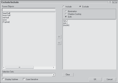
Figure 19.8. The Exclude/Include dialog box lets you set which objects are excluded or included from being illuminated.
As an example of the Exclude/Include feature, Figure 19.9 shows the elk model with the antlers (left) and its body (right) excluded from the shadows pass.
In the Intensity/Color/Attenuation rollout, the Multiplier value controls the light intensity. A light with a Multiplier set to 2 is twice as bright as a light with its Multiplier set to 1. Higher Multiplier values make a light appear white regardless of the light color. The Multiplier value can also be negative. A negative value can be used to pull light from a scene but should be used with caution.
Tip
Adding and positioning another light typically is better than increasing the multiplier.
To the right of the Multiplier value is a color swatch. Clicking the color swatch opens a color selector where you can choose a new light color.
Attenuation is a property that determines how light fades over distance. An example of this is a candle set in a room. The farther you get from the candle, the less the light shines.
You use three basic parameters to simulate realistic attenuation. Near Attenuation sets the distance at which the light begins to fade, and Far Attenuation sets the distance at which the light falls to 0. Both these properties are ranges that include Start and End values. The third parameter sets the Decay value, which simulates attenuation using a mathematical formula to compute the drop in light intensity over time.
Selecting the Use option enables the Near and Far Attenuation values; both have Start and End values that set the range for these attenuation types. The Show option makes the attenuation distances and decay values visible in the viewports. The three types of decay from which you can choose are None, Inverse, and Inverse Square. The Inverse type decays linearly with the distance away from the light. The Inverse Square type decays exponentially with distance.
Note
The Inverse Square type approximates real lights the best, but it is often too dim for computer graphic images. You can compensate for this by increasing the Multiplier value.
The Spotlight Parameters rollout includes values to set the angular distance of both the Hot Spot and Falloff cones. The Show Cone option makes the Hotspot and Falloff cones visible in the viewport when the light is not selected. The Overshoot option makes the light shine in all directions like an Omni light, but projections and shadows occur only within the Falloff cone. You can also set the light shape to be circular or rectangular. For a rectangular-shaped spotlight, you can control the aspect ratio. You can use the Bitmap Fit button to make the aspect ratio match a particular bitmap.
The Directional Light Parameters rollout, which appears for Direct light types, is identical to the Spotlight Parameters rollout and also includes settings for the Hot Spot and Falloff values.
Options in the Affect Surface section of the Advanced Effects rollout control how light interacts with an object's surface. The Contrast value alters the contrast between the diffuse and the ambient surface areas. The Soften Diffuse Edge value blurs the edges between the diffuse and ambient areas of a surface. The Diffuse and Specular options let you disable these properties of an object's surface. When the Ambient Only option is turned on, the light affects only the ambient properties of the surface.
Note
Find more detail on the Diffuse, Specular, and Ambient properties in Chapter 14, "Exploring the Material Editor."
You can use any light as a projector; you find this option in the Advanced Effects rollouts. Selecting the Map option enables you to use the light as a projector. You can select a map to project by clicking the button to the right of the map option. You can drag a material map directly from the Material/Map Browser onto the Projector Map button.
All light types have a Shadow Parameters rollout that you can use to select a shadow color by clicking the color swatch. The default color is black. The Dens setting stands for "Density" and controls how dark the shadow appears. Lower values produce light shadows, and higher values produce dark shadows. This value can also be negative.
The Map option, like the Projection Map, can be used to project a map along with the shadow color. The Light Affects Shadow Color option alters the Shadow Color by blending it with the light color if selected.
In the Atmosphere Shadows section, the On button lets you determine whether atmospheric effects, such as fog, can cast shadows. You can also control the Opacity and the degree to which atmospheric colors blend with the Shadow Color.
When you select a light and open the Modify panel, one additional rollout is available: the Atmospheres and Effects rollout. This rollout is a shortcut to the Environment dialog box, where you can specify atmospheric effects such as fog and volume lights.
Note
The only effects that can be used with lights are Volume Light and Lens Effects.
Note
Chapter 45, "Using Atmospheric and Render Effects," covers atmospheric effects.
If the Area Shadows option is selected in the General Parameters rollout, then the Area Shadows rollout appears, which includes several settings for controlling this shadow type. In the drop-down list at the top of the rollout, you can select from several Basic Options, including Simple, Rectangle Light, Disc Light, Box Light, and Sphere Light. You can select dimensions depending on which option is selected. You can also set the Integrity, Quality, Spread, Bias, and Jitter amounts.
For the Shadow Map option, the Shadow Map Params rollout includes values for the Bias, Size, and Sample Range. The Sample Range value softens the shadow edges. You can also select to use an Absolute Map Bias and 2 Sided Shadows.
If the Ray Traced Shadows option is selected in the Shadow Parameters rollout, the Ray Traced Shadows Parameters rollout appears below it. This simple rollout includes only two values: Bias and Max Quadtree Depth. The Bias settings cause the shadow to move toward or away from the object that casts the shadow. The Max Quadtree Depth determines the accuracy of the shadows by controlling how long the ray paths are followed. There is also an option to enable 2 Sided Shadows, which enables both sides of a face to cast shadows, including backfacing objects.
For the Advanced Raytraced Shadows options, the rollout includes many more options, including Simple, 1-Pass, or 2-Pass Anti-aliasing. This rollout also includes the same quality values found in the Area Shadows rollout.
Note
Depending on the number of objects in your scene, shadows can take a long time to render. Enabling raytraced shadows for a complex scene can greatly increase the render time.
If you select either the Area Shadows type or the Advanced Raytracing Shadows type, then a separate Optimizations rollout appears. This rollout includes settings that help speed up the shadow rendering process. Using this rollout, you can enable Transparent Shadows. You can also specify a color that is used at the Anti-aliasing Threshold. You can also turn off anti-aliasing for materials that have SuperSampling or Reflection/Refraction enabled. Or you can have the shadow renderer skip coplanar faces with a given threshold.
When the Select and Manipulate mode is enabled on the main toolbar, the end of the Hotspot and Falloff cones appear green for a selected spotlight. When you move the mouse over these lines, the lines turn red, allowing you to drag the lines and make the Hotspot and/or Falloff angle values greater. These manipulators provide visual feedback as you resize the spotlight cone.
Several of the light rollouts for photometric lights are the same as those for the standard lights, but several key parameters are unique for photometric lights, such as the ability to choose a light distribution model and a shape type.
The Distribution options are listed in a drop-down list in the General rollout. Both Free and Target photometric lights can be set to one of four distribution types. Each of these types appears as a different icon in the viewports:
Uniform Spherical: This distribution type emanates light equally in all directions from a central point, like the standard Omni light.
Uniform Diffuse: This distribution type spreads light equally in all directions for only one hemisphere, such as when a light is positioned against a wall.
Spotlight: This distribution type spreads the light in a cone shape, like a flashlight or a car's headlight.
Photometric Web: This distribution type can be any arbitrary 3D representation and is defined in a separate file that can be obtained from the light manufacturer and loaded into the light object. Once loaded, the distribution graph is visible in the Distribution rollout.
The Uniform Spherical option distributes light equally in all directions. The Uniform Diffuse option has its greatest distribution at right angles to the surface it is emitted from and gradually decreases in intensity at increasing angles from the normal. For both options, the light gradually becomes weaker as the distance from the light increases.
The Spotlight option concentrates the light energy into a cone that emits from the light. This cone of light energy is directional and can be controlled with the Hotspot and Falloff values.
The Photometric Web option is a custom option that lets you open a separate file describing the light's emission pattern. These files have the .ies, .cibse, or .ltli extensions. Light manufacturers have this data for the various real-world lights that they sell. You load these files using the Choose Photometric File button found in the Distribution (Photometric Web) rollout. You can also specify the X-, Y-, and Z-axis rotation values.
The Color section of the Intensity/Color/Attenuation rollout, shown in Figure 19.10, includes two ways to specify a light's color. The first is a drop-down list of options. The options found in the list include standard real-world light types such as Cool White, Mercury, and Halogen. Table 19.2 lists each of these types and its approximate color.
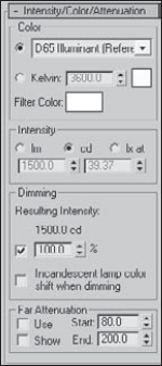
Figure 19.10. The Intensity/Color/Attenuation rollout for photometric lights uses real-world intensity values.
Table 19.2. Photometric Light Colors
Light Type | Color |
|---|---|
Cool White | Yellow-white |
Custom | Any color |
D65White | White |
Daylight Fluorescent | Mostly white with a slight gray tint |
Fluorescent | Yellow-white |
Halogen | Beige-white |
High-Pressure Sodium | Tan |
Incandescent | Beige-white |
Low Pressure Sodium | Light orange |
Mercury | Green-white |
Metal Halide | Yellow-white |
Phosphor Mercury | Light green |
Quartz | Yellow-white |
White Fluorescent | Yellow-white |
Xenon | White |
In addition to a list of available light types, you can specify a color based on temperature expressed in degrees Kelvin. Temperature-based colors run from a cool 1,000 degrees, which is a mauve-pink color, through light yellow and white (at 6,000 degrees Kelvin) to a hot light blue at 20,000 degrees Kelvin. Typical indoor lighting is fairly low on the Kelvin scale at around 3300 degrees K. Direct sunlight is around 5500 degrees K. Thunderbolts, arc welders, and electric bolts run much hotter, from 10,000 to 20,000 degrees Kelvin.
You also can set a Filter Color using the color swatch found in this section. The Filter Color simulates the color caused by colored cellophane placed in front of the light.
The Intensity options can be specified in Lumens, Candelas, or Lux at a given distance. Light manufacturers have this information available. You also can specify a Multiplier value, which determines how effective the light is. There is also a setting for specifying the intensity due to a dimming effect, and the Incandescent lamp color shift when dimming option causes the light from an incandescent light to turn more yellow as it is dimmed. This effect is common as you get further from a light bulb.
Note
The Incandescent lamp color shift when dimming option is new to 3ds Max 2009.
All real-world lights have attenuation, and Far attenuation values can be also be set for photometric lights. This helps to speed up rendering times for scenes with lots of lights by limiting the extent of the cast light rays.
Note
The Far Attenuation value is also new to 3ds Max 2009.
In addition to the distribution type, you can also select the light shape, which has an impact on how shadows are cast in the scene. Selecting a different-shaped light causes the light to be spread over a wider area, so in most cases, the Point light results in the brightest intensity with sharper shadows and lights covering a larger area are less intense and have softer shadows. The available photometric light shapes include the following:
Point: This shape emits light from a single point like light bulb.
Line: This shape emits light from a straight line like a fluorescent tube.
Rectangle: This shape emits light from an area like a bank of fluorescent lights.
Disc: This shape emits light from a circular area like the light out of the top of a shaded lamp.
Sphere: This shape emits light from a spherical shape like a Chinese lantern.
Cylinder: This shape emits light from a cylindrical shape like some kinds of track lighting.
Note
The Disc, Sphere, and Cylinder light shapes are new to 3ds Max 2009.
For each shape you can set the shape's dimensions in the Shape/Area Shadows rollout. The rollout also lets you switch between the different shapes. If you need to see the actual light shape, then you can enable the Light Shape Visible in Rendering option in the Shape/Area Shadows rollout.
The Sunlight and Daylight systems, accessed through the Systems category of the Create panel, create a light that simulates the sun for a specific geographic location, date, time, and compass direction.
Note
The Daylight system can be created using the Create
To create either of these systems, open the Create panel and click the Systems category button. Then click the Sunlight (or Daylight) button, and drag the mouse in a viewport. A Compass helper object appears. Click again to create a Direct light (or Skylight) representing the sun. Figure 19.11 shows the Compass helper created as part of the Sunlight system. The main difference between these two systems is that the Sunlight system uses a Directional light and the Daylight system uses the IES Sun and Sky lights.
Note
The Compass helper object's orientation aligns with the ViewCube's directions.
Tip
The best results for the Daylight system are realized when you use the mr Sun and mr Sky options. Using the Daylight system with these options also enables the mr Physical Sky environment settings. More on this system is covered in Chapter 46, "Raytracing and mental ray."
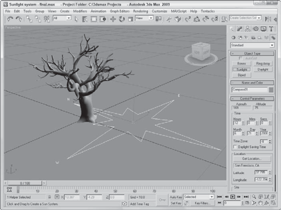
Figure 19.11. The Compass helper provides an orientation for positioning the sun in a Sunlight system.
The Compass helper is useful when working with a Sunlight system. It can be used to define the map directions of North, East, South, and West. The Sunlight system uses these directions to orient the system light. This helper is not renderable and is created automatically when you define a sunlight object. The Compass helper object is found in the Create
After you create a Sunlight system, you can alter the point that the sun is pointing at by transforming the Compass helper. Doing so causes the direct light object to move appropriately. The light's position in the sky is controlled by the Time, Date, and Location parameters, but if you want to move the light independent of these parameters, you can select the Manual option and move the light using the transform tools.
Note
You can change the settings for the light that is the sun by selecting the light from the Select by Name dialog box and opening the Modify panel. The sunlight object uses raytraced shadows by default.
Once created, the light parameters for the Daylight system, including light intensity and shadows, are located in the Modify panel, but the Date, Time, and Location parameters are in the Motion panel when the light object is selected. You can access the Motion panel parameters by clicking the Setup button in the Daylight Parameters rollout.
Azimuth and Altitude are two values that help define the location of the sun in the sky. Both are measured in degrees. Azimuth refers to the compass direction and can range from 0 to 360, with 0 degrees being North, 90 degrees being East, 180 degrees being South, and 270 degrees being West. Altitude is the angle in degrees between the sun and the horizon. This value ranges typically between 0 and 90, with 0 degrees being either sunrise or sunset and 90 degrees when the sun is directly overhead.
The Time section of the Control Parameters rollout lets you define a time and date. The Time Zone value is the number of offset hours for your current time zone. You can also set the time to be converted for Daylight Saving Time.
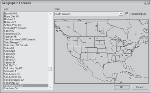
Clicking the Get Location button in the Control Parameters rollout opens the Geographic Location dialog box, shown in Figure 19.12, which displays a map or a list of cities. Selecting a location using this dialog box automatically updates the Latitude and Longitude values. In addition to the Get Location button, you can enter Latitude and Longitude values directly in the Control Parameters rollout.
The Daylight system also includes an option to set the Sky value from Clear to Partly Cloudy to Cloudy.
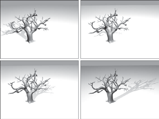
You can animate the Sunlight system to show an entire day from sunrise to sundown in a short number of frames. In this tutorial, you focus on an old tree positioned somewhere in Phoenix, Arizona, on Christmas. The tree certainly won't move, but watch its shadows.
To use the Sunlight system to animate shadows, follow these steps:
Open the Sunlight system.max file from the Chap 19 directory on the DVD.
This file includes a tree mesh created by Zygote.
Add a Sunlight System by selecting the Systems category in the Create panel and clicking the Sunlight button. Then drag in the Top view to create the Compass helper, and click again to create the light. In the Control Parameters rollout (found in the Motion panel), enter 12/25 and the current year for the Date and an early morning hour for the Time.
Click the Get Location button, locate Phoenix in the Cities list, and click OK. Rotate the compass helper in the Top view so that north is pointing toward the top of the viewport.
Click the Auto Key button (or press the N key), and move the Time slider to frame 100.
In the Control Parameters rollout, change the Time value to an evening hour. Then click the Auto Key button (N) again to disable animation mode.
Note
You can tell when the sun comes up and goes down by looking at the Altitude value for each hour. A negative Altitude value indicates that the sun is below the horizon.
Figure 19.13 shows a snapshot of this quick day. The upper-left image shows the animation at frame 20, the upper-right image shows it at frame 40, the lower-left image shows it at frame 60, and the final image shows it at frame 80.
When light shines through fog, smoke, or dust, the beam of the light becomes visible. The effect is known as a Volume Light. To add a Volume Light to a scene, choose Rendering
You can also access the Volume Light effect from the Atmospheres and Effects rollout in the Modify panel when a light is selected.
Note
Chapter 45, "Using Atmospheric and Render Effects," covers the other atmospheric effects.
At the top of the Volume Light Parameters rollout, shown in Figure 19.14, is a Pick Light button, which enables you to select a light to apply the effect to. You can select several lights, which then appear in a drop-down list. You can remove lights from this list with the Remove Light button.
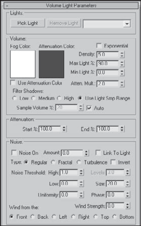
Figure 19.14. The Volume Light Parameters rollout in the Environment dialog box lets you choose which lights to include in the effect.
In the Volume section, the Fog Color swatch lets you select a color for the fog that is seen within the light. This color is combined with the color of the light. The Attenuation Color is the color the fog appears to have at a distance far from the light source. This color also combines with the Fog Color and is best set to a dark color.
The Density value determines the thickness of the fog. The Exponential option causes the density to increase exponentially with the distance. The Max and Min Light Percentage values determine the amount of glow that the volume light causes, and the Attenuation Multiplier controls the strength of the attenuation color.
You have four options for filtering shadows: Low, Medium, High, and Use Light Smp Range. The Low option renders shadows quickly but isn't very accurate. The High option takes a while but produces the best quality. The Use Light Smp Range option bases the filtering on the Sample Volume value and can be set to Auto. The Sample Volume can range from 1 to 10,000. The Low option has a Sample Volume value of 8; Medium, 25; and High, 50.
Note
Only Shadow Map type shadows cast shadows through volume fog.
The Start and End Attenuation values are percentages of the Start and End range values for the light's attenuation. These values have an impact only if attenuation is turned on for the light.
The Noise settings help to determine the randomness of Volume Light. Noise effects can be turned on and given an Amount. You can also Link the noise to the light instead of using world coordinates. Noise types include Regular, Fractal, and Turbulence. Another option inverts the noise pattern. The Noise Threshold limits the effect of noise. Wind settings affect how the light moves as determined by the wind's direction, Wind Strength, and Phase.
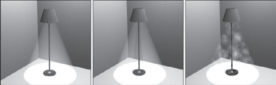
Figure 19.15 shows several volume light possibilities. The left image includes the Volume Light effect, the middle image enables shadows, and the right image includes some Turbulent Noise.
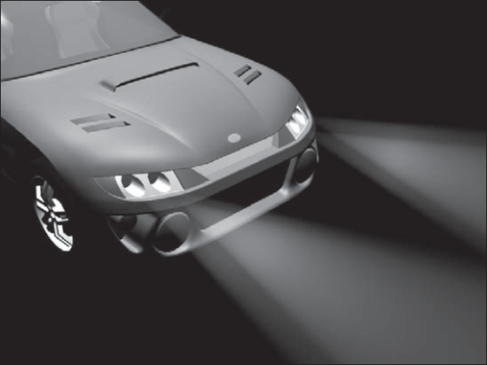
One popular way to use volume lights is to display the headlights of cars. For this tutorial, you're going to use the Delfino Feroce 2001 car model created by Viewpoint Datalabs.
To display the headlights of a car, follow these steps:
Open the Car headlights.max file from the Chap 19 directory on the DVD.
This file includes a model of a car.
Select the Create
Open the Modify panel, and in the Spotlight Parameters rollout, set the Hotspot value to 20, the Falloff to 25, and in the Intensity/Color/Attenuation rollout, set the Decay setting to Inverse Square with a Start value of 3.0. In the Atmospheres and Effects rollout, click the Add button, select Volume Light from the Add Atmosphere or Effect dialog box that appears, and click OK.
Note
When a light is added to the scene, the default lights are automatically turned off. To provide any additional lighting, add some Omni lights above the car.
Select the Volume Light effect in the list within the Atmospheres and Effects rollout, and click the Setup button. The Environment dialog box opens, in which you can edit the Volume Light parameters for the newly created light. Set the Density value to 100.
Now create three more headlights. To do this, select both the first spotlight object and its target, and create a cloned copy by holding down the Shift key while moving it toward the right headlight. Position the other spotlights so that they shine outward from the other headlights.
Figure 19.16 shows the resulting car with its headlights illuminated.
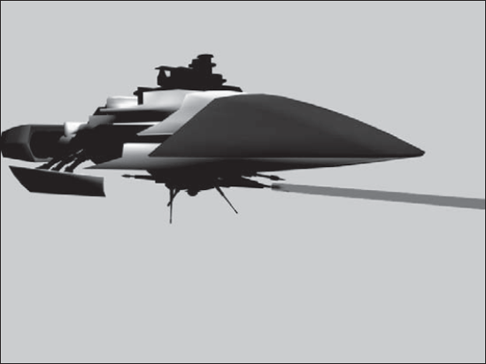
Laser beams are extremely useful lights. From your CD-ROM drive to your laser printer, lasers are found throughout a modern-day office. They also are great to use in fantasy and science fiction images. You can easily create laser beams using direct lights and the Volume Light effect. In this tutorial, you'll add some lasers to the spaceship model created by Viewpoint Datalabs.
To add some laser beams to a scene, follow these steps:
Open the Spaceship laser.max file from the Chap 19 directory on the DVD.
This file includes a spaceship model.
Select the Create
With the light selected, open the Modify panel. In the Atmospheres and Effects rollout, click the Add button and double-click the Volume Light selection. Then select the Volume Light option in the list, and click the Setup button to open the Environment dialog box. Change the Fog Color to red and the Density value to 50 and make sure that the Use Attenuation Color is disabled.
With the direct lights added to the scene, the default lights are deactivated, so you need to add some Omni lights above the spaceship to illuminate it. To do this, select the Create
Figure 19.17 shows the resulting laser beams shooting forth from the spaceship.
If a map is added to a light in the Parameters rollout, the light becomes a projector. Projector maps can be simple images, animated images, or black-and-white masks to cast shadows. To load a projector map, select a light and open the Modify panel. Under the Spotlight Parameters rollout, click the Projector Map button and select the map to use from the Material/Map Browser.
Raytraced shadows take longer to render than the Shadow Maps or Area Shadows option, but the shadows always have a hard edge and are an accurate representation of the object.
Note
You can create shadows for wireframe objects with transparency only by using raytraced shadows.
In the Shadow Parameters rollout, you can select whether shadows are computed using shadow maps or raytraced shadows. Using the latter selection lets you project a transparent object's color onto the shadow.
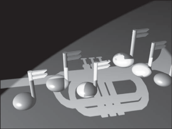
As an example of a projector light, you create a musical scene with several musical notes and project the image of a trumpet on them.
To project an image onto a rendered scene, follow these steps:
Open the Trumpet mask.max file from the Chap 19 directory on the DVD.
This file includes a trumpet model shown in the maximized Left viewport. This file is used to generate a project map.
Choose Rendering
Open the Musical notes.max file from the Chap 19 directory on the DVD.
This file contains several musical notes created from primitive objects.
Select the Create
Open the Modify panel; in the Advanced Effects rollout, click the Projector Map button and double-click Bitmap from the Material/Map Browser. Locate and select the Trumpet Mask.tif file, and click Open. This projects a silhouette of a trumpet onto the scene. Use the second spotlight to light the music notes.
Figure 19.18 shows the musical notes with the trumpet projection map.
When a light that uses raytraced shadows shines through an object with transparent materials, the Filter color of the material is projected onto objects behind. In this tutorial, you create a stained-glass window and shine a light through it using raytraced shadows.
To create a stained-glass window, follow these steps:
Open the Stained glass window.max file from the Chap 19 directory on the DVD.
This file includes a stained-glass window for a fish market. (Don't ask me why a fish market has a stained-glass window.)
Select the Create
This creates a target spotlight that shines through the stained-glass window onto the floor behind it.
In the General Parameters rollout, make sure that the On option is enabled in the Shadows section and select Ray Traced Shadows from the drop-down list.
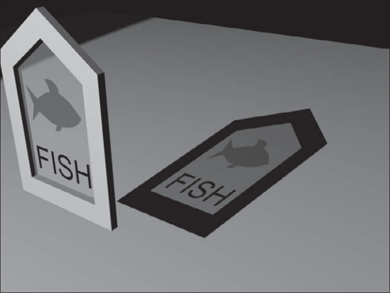
Figure 19.19 shows the stained-glass window with the colored shadow cast on the scene floor.
I hope you have found this chapter enlightening. (Sorry about the bad pun, but I need to work them in where I can.) Max has many different lights, each with plenty of controls. Learning to master these controls can take you a long way toward increasing the realism of the scene. In this chapter, you've accomplished the following:
Learned the basics of lighting
Discovered Max's standard and photometric light types
Created and positioned light objects
Learned to change the viewport view to a light
Used the Sunlight and Daylight systems
Used the Volume Light atmospheric effect
Added projection maps to lights
Used raytraced shadows to create a stained-glass window
In the next chapter you finally start animating objects, beginning with the basics, including keyframing.