
Max can be used to create some really amazing images, but I bet more of you go to the movies than go to see images in a museum. The difference is in seeing moving images versus static images.
In this chapter, I start discussing what is probably one of the main reasons you decided to learn 3ds Max in the first place—animation. Max includes many different features to create animations. This chapter covers the easiest and most basic of these features—keyframe animation.
Along the way, you'll examine all the various controls that are used to create, edit, and control animation keys, including the Time Controls, the Track Bar, and the Motion panel. Keyframes can be used to animate object transformations, but they also can be used to animate other parameters such as materials. If you get finished with this chapter in time, you may have time to watch a movie.
Before jumping into animation, you need to understand the controls that make it possible. These controls collectively are called the Time Controls and can be found on the lower interface bar between the key controls and the Viewport Navigation Controls. The Time Controls also include the Time Slider found directly under the viewports.
The Time Slider provides an easy way to move through the frames of an animation. To do this, just drag the Time Slider button in either direction. The Time Slider button is labeled with the current frame number and the total number of frames. The arrow buttons on either side of this button work the same as the Previous and Next Frame (Key) buttons.
The Time Control buttons include buttons to jump to the Start or End of the animation, or to step forward or back by a single frame. You can also jump to an exact frame by entering the frame number in the frame number field. The Time Controls are presented in Table 20.1.
Table 20.1. Time Controls
The default scene starts with 100 frames, but this is seldom what you actually need. You can change the number of frames at any time by clicking the Time Configuration button, which is to the right of the frame number field. Clicking this button opens the Time Configuration dialog box, shown in Figure 20.1. You can also access this dialog box by right-clicking any of the Time Control buttons.
Within this dialog box, you can set several options, including the Frame Rate. Frame rate provides the connection between the number of frames and time. It is measured in frames per second. The options include standard frame rates such as NTSC (National Television Standards Committee, around 30 frames per second), Film (around 24 frames per second), and PAL (Phase Alternate Line, used by European countries, around 25 frames per second), or you can select Custom and enter your own frame rate.
The Time Display section lets you set how time is displayed on the Time Slider. The options include Frames, SMPTE (Society of Motion Picture Technical Engineers), Frame:Ticks, or MM:SS:Ticks (Minutes and Seconds). SMPTE is a standard time measurement used in video and television. A Tick is 1/4800 of a second.
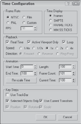
The Playback section sets options for how the animation sequence is played back. The Real Time option skips frames to maintain the specified frame rate. The Active Viewport Only option causes the animation to play only in a single viewport, which speeds up the animation. The Loop option repeats the animation over and over. The Loop option is available only if the Real Time option is disabled. If the Loop option is set, then you can specify the Direction as Forward, Reverse, or Ping-Pong (which repeats playing forward and then reverse). The Speed setting can be ¼, ½, 1, 2, or 4 times normal.
The Time Configuration dialog box also lets you specify the Start Time, End Time, Length, and Current Time values. These values are all interrelated, so setting the Length and the Start Time, for example, automatically changes the End Time. These values can be changed at any time without destroying any keys. For example, if you have an animation of 500 frames and you set the Start and End Time to 30 and 50, the Time Slider controls only those 21 frames. Keys before or after this time are still available and can be accessed by resetting the Start and End Time values to 0 and 500.
The Re-scale Time button fits all the keys into the active time segment by stretching or shrinking the number of frames between keys. You can use this feature to resize the animation to the number of frames defined by Start and End Time values.
The Key Steps group lets you set which key objects are navigated using key mode. If you select Use Track Bar, key mode moves through only the keys on the Track Bar. If you select the Selected Objects Only option, key mode jumps only to the keys for the currently selected object. You can also filter to move between Position, Rotation, and Scale keys. The Use Current Transform option locates only those keys that are the same as the current selected transform button.
It isn't just a coincidence that the largest button in the entire Max interface has a key on it. Creating and working with keys is how animations are accomplished. Keys define a particular state of an object at a particular time. Animations are created as the object moves or changes between two different key states. Complex animations can be generated with only a handful of keys.
You can create keys in numerous ways, but the easiest is with the Key Controls found on the lower interface bar. These controls are located to the left of the Time Controls. Table 20.2 displays and explains all these controls. Closely related to the Key Controls is the Track Bar, which is located under the Time Slider.
Table 20.2. Key Controls
Toolbar Button | Name | Description |
|---|---|---|
Set Key (K) | Creates animation keys in Set Key mode | |
Sets keys automatically for the selected object when enabled | ||
Toggle Set Key Mode (') | Sets keys as specified by the key filters for the selected object when enabled | |
Selection Set drop-down list | Specifies a selection set to use for the given keys | |
Default In/Out Tangents for New Keys | Assigns the default tangents that are used on all new keys | |
Open Filters Dialog box | Contains pop-up options for the filtering keys |
Max includes two animation modes: Auto Key (N) and Set Key ('). You can select either of these modes by clicking the respective buttons at the bottom of the interface. When active, the button turns bright red, and the border around the active viewport also turns red to remind you that you are in animate mode. Red also appears around a spinner for any animated parameters.
With the Auto Key button enabled, every transformation or parameter change creates a key that defines where and how an object should look at that specific frame.
To create a key, drag the Time Slider to a frame where you want to create a key and then move the selected object or change the parameter, and a key is automatically created. When the first key is created, Max automatically goes back and creates a key for frame 0 that holds the object's original position or parameter. Upon setting the key, Max then interpolates all the positions and changes between the keys. The keys are displayed in the Track Bar.
Each frame can hold several different keys, but only one for each type of transform and each parameter. For example, if you move, rotate, scale, and change the Radius parameter for a sphere object with the Auto Key mode enabled, then separate keys are created for position, rotation, scaling, and a parameter change.
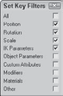
The Set Key button (') offers more control over key creation and sets keys only when you click the Set Key button (K). It also creates keys only for the key types enabled in the Key Filters dialog box. You can open the Key Filters dialog box, shown in Figure 20.2, by clicking the Key Filters button. Available key types include All, Position, Rotation, Scale, IK Parameters, Object Parameters, Custom Attributes, Modifiers, Materials, and Other (which allows keys to be set for manipulator values).
The best way to learn is to practice, and there's no better time to practice than now. For this quick example, you animate a set of blades on a windmill.
To animate a set of windmill blades rotating, follow these steps:
Open the Rotating windmill blades.max file from the Chap 20 directory on the DVD.
This file includes a windmill model created by Viewpoint Datalabs.
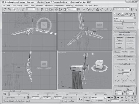
Click the Auto Key button (or press the N key) at the bottom of the Max window, and drag the Time Slider to frame 50.
Select the "prop" object at the top of the windmill in the Front viewport. The blades are attached to the center prop and rotate about its Pivot Point. Then click the Select and Rotate button on the main toolbar (or press E key), and rotate the "prop" object about its Y-axis.
Click the Auto Key button (or press the N key) again to disable animation mode. Select the key in the Track Bar located at frame 1, hold down the Shift key, and drag the key to frame 100 (or press the End key).
This step copies the key from frame 1 to frame 100. Doing so ensures a smooth looping animation (even though it spins the prop forward and then backward; I guess it must be a strange wind that's blowing).
Click the Play Animation button in the Time Controls to see the animation.
Figure 20.3 shows frame 50 of this simple animation.
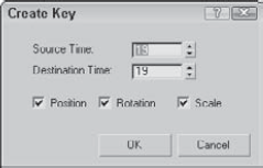
Another way to create keys is to select the object to be animated and right-click the Time Slider button. This opens the Create Key dialog box, shown in Figure 20.4, where you can set Position, Rotation, and Scale keys for the currently selected object. You can use this method only to create transform keys.
If a key already exists, you can clone it by dragging the selected key with the Shift key held down. Dragging the Track Bar with the Ctrl and Alt keys held down changes the active time segment.
If a parameter is changed while the Auto Key mode is enabled, then keys are set for that parameter. You can tell when a parameter has a key set because the arrows to the right of its spinner are outlined in red when the Time Slider is on the frame where the key is set. If you change the parameter value when the spinner is highlighted red, then the key value is changed (and the Auto Key mode doesn't need to be enabled).
If you highlight and right-click the parameter value, a pop-up menu of options appears. Using this pop-up menu, you can Cut, Copy, Paste, and Delete the parameter value. You can also select Copy Animation, which copies all the keys associated with this parameter and lets you paste them to another parameter. Pasting the animation keys can be done as a Copy, an Instance, or a Wire. A Copy is independent; an Instance ties the animation keys to the original copy so that they both are changed when either changes; and a Wire lets one parameter control some other parameter.
Warning
To copy a parameter value, be sure to select and right-click the value. If you right-click the parameter's spinner, the value is set to 0.
The right-click pop-up menu also includes commands to let you Edit a wired parameter, show the parameter in the Track View, or show the parameter in the Parameter Wire dialog box.
Note
Parameter wiring and the Parameter Wire dialog box are discussed in more detail in Chapter 32, "Using Animation Modifiers."
The Max interface includes a simple way to work with keys: with the Track Bar, which is situated directly under the Time Slider. The Track Bar displays a rectangular marker for every key for the selected object. These markers are color-coded, depending on the type of key. Position keys are red, rotation keys are green, scale keys are blue, and parameter keys are dark gray.
Warning
In the Track View—Dope Sheet interface, position, rotation, and scale keys are red, green, and blue, but parameter keys are yellow.
The current frame also appears in the Track Bar as a light blue, transparent rectangle, as shown in Figure 20.5. The icon at the left end of the Track Bar is the Open Mini Curve Editor button, which opens a mini Track View.
Note
For more on the Track View interface, see Chapter 34, "Working with Function Curves in the Track View."
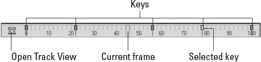
Using the Track Bar, you can move, copy, and delete keys. The Track Bar shows key markers only for the currently selected object or objects, and each marker can represent several different keys. When the mouse is moved over the top of these markers, the cursor changes to a plus sign, and you can select a marker by clicking it (selected markers turn white). Using the Ctrl key, you can select multiple keys at the same time. You can also select multiple key markers by clicking an area of the Track Bar that contains no keys and then dragging an outline over all the keys you want to select. If you move the cursor over the top of a selected key, the cursor is displayed as a set of arrows enabling you to drag the selected key to the left or right. Holding down the Shift key while dragging a key creates a copy of the key. Pressing the Delete key deletes the selected key.
Tip
If you drag a key off the end of the Track Bar, the frame number is displayed on the Prompt Line at the bottom of the interface and the key is not included in the current time range. If you ever want to hide a key without deleting it, you can drag it off the end of the Track Bar and recover it by resetting the time in the Time Configuration dialog box.
Because each marker can represent several keys, you can view all the keys associated with the marker in a pop-up menu by right-clicking the marker.
Note
In the pop-up menu, a check mark next to a key indicates that the key is shared with another instance.
The marker pop-up menu also offers options for deleting selected keys or filtering the keys. In addition, there is a Goto Time command, which automatically moves the Time Slider to the key's location when selected.
To delete a key marker with all of its keys, right-click to open the pop-up menu and choose Delete Key
At the top of the marker's right-click pop-up menu is a list of current keys for the selected object (or if there are too many keys for a marker, they are placed under the Key Properties menu). When you select one of these keys, a key information dialog box opens. This dialog box displays different controls depending on the type of key selected. Figure 20.6 shows the dialog box for the Position key. There are slight variations in this dialog box, depending on the key type.

Note
You can also access key-specific dialog boxes in the Motion panel for a selected object by clicking the Parameters button.
Within each of these key dialog boxes is a Time value that shows the current frame. Next to the Time value are two arrows that enable you to move easily to the other keys in the scene. The dialog box also includes several text fields, where you can change the key parameters.
Most of the key dialog boxes also include flyout buttons for selecting Key Tangents. Key Tangents determine how the animation moves into and out of the key. For example, if the In Key Tangent is set to Slow and the Out Key Tangent is set to Fast, the object approaches the key position in a slow manner but accelerates as it leaves the key position. The arrow buttons on either side of the Key Tangent buttons can copy the current Key Tangent selection to the previous or next key.
The available types of Tangents are detailed in Table 20.3.
Table 20.3. Key Tangents
Toolbar Button | Name | Description |
|---|---|---|
Smooth | Produces straight, smooth motion; this is the default type. | |
Linear | Moves at a constant rate between keys. | |
Step | Causes discontinuous motion between keys; it occurs only between matching In-Out pairs. | |
Slow | Decelerates as you approach the key. | |
Fast | Accelerates as you approach the key. | |
Custom | Lets you control the Tangent handles in function curves mode. | |
Custom – Locked Handles | Lets you control the Tangent handles in function curves mode with the handles locked. |
You have yet another way to create keys: by using the Motion panel. The Motion panel in the Command Panel includes settings and controls for animating objects. At the top of the Motion panel are two buttons: Parameters and Trajectories.
The Parameters button on the Motion panel lets you assign controllers and create and delete keys. Controllers are custom key-creating algorithms that can be defined through the Parameters rollout, shown in Figure 20.7. You assign these controllers by selecting the position, rotation, or scaling track and clicking the Assign Controller button to open a list of applicable controllers that you can select.
Note
For more information on controllers, see Chapter 21, "Animating with Constraints and Controllers."
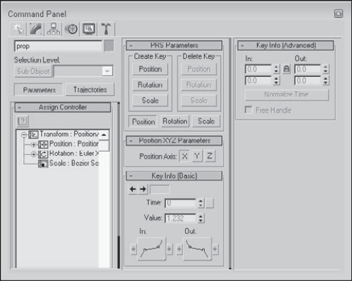
Figure 20.7. The Parameters section of the Motion panel lets you assign controllers and create keys.
Below the Assign Controller rollout is the PRS Parameters rollout, where you can create and delete Position, Rotation, and Scale keys. You can use this rollout to create Position, Rotation, and Scale keys whether or not the Auto Key or Set Key buttons are enabled. Additional rollouts may be available, depending upon the selected controller.
Below the PRS Parameters rollout are two Key Info rollouts: Basic and Advanced. These rollouts include the same key-specific information that you can access using the right-click pop-up menu found in the Track Bar.
A trajectory is the actual path that the animation follows. When you click the Trajectories button in the Motion panel, the animation trajectory is shown as a spline with each key displayed as a node and each frame shown as a white dot. You can then edit the trajectory and its nodes by clicking the Sub-Object button at the top of the Motion panel, shown in Figure 20.8. The only subobject available is Keys. With the Sub-Object button enabled, you can use the transform buttons to move and reposition the trajectory nodes. You can also add and delete keys with the Add Key and Delete Key buttons.
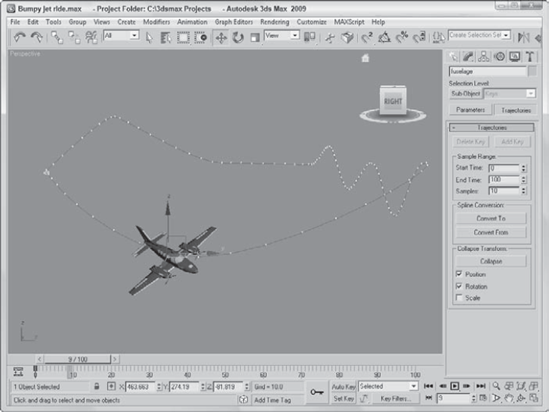
Figure 20.8. The Trajectories rollout in the Motion panel enables you to see the animation path as a spline.
For more control over the trajectory path, you can convert the trajectory path to a normal editable spline with the Convert To button. You can also convert an existing spline into a trajectory with the Convert From button.
To use the Convert From button, select an object, click the Convert From button, and then click a spline path in the scene. This creates a new trajectory path for the selected object. The first key of this path is placed at the spline's first vertex, and the final key is placed as the spline's final vertex position. Additional keys are spaced out along the spline based on the spline's curvature as determined by the Samples value listed in the Sample Range group. All these new keys are roughly spaced between the Start and End times, but smaller Bézier handles result in more closely packed keys.
Click the Collapse button at the bottom of the Trajectories rollout to reduce all transform keys into a single editable path. You can select which transformations to collapse, including Position, Rotation, and Scale, using the options under the Collapse button. For example, an object with several Controllers assigned can be collapsed, thereby reducing the complexity of all the keys.
Note
If you collapse all keys, you cannot alter their parameters via the controller rollouts.
The Views menu includes an option to Show Key Times. The Show Key Times command displays frame numbers along the trajectory path where every animation key is located. Enabling this option displays the frame numbers next to any key along a trajectory path. You can make the trajectory visible for any object by enabling the Trajectory option in the Object Properties dialog box.
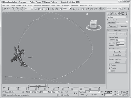
Airplanes that perform aerobatic stunts often follow paths that are smooth. You can see this clearly when watching a sky writer. In this example, I've created a simple looping path using the Line spline primitive, and you'll use this path to make a plane complete a loop.
To make an airplane follow a looping path, follow these steps:
Open the Looping airplane.max file from the Chap 20 directory on the DVD.
This file includes a simple looping spline path and an airplane created by Viewpoint Datalabs.
With the airplane selected, open the Motion panel and click the Trajectories button. Then click the Convert From button in the Trajectories rollout, and select the path in the Front viewport.
If you drag the Time Slider, you'll notice that the plane moves along the path, but it doesn't rotate with the path. To fix this, click the Key Mode Toggle button in the Time Controls to easily move from key to key. Click the Key Filters button, select only Rotation, and then click the Set Key button (or press the ' key) to enter Set Key mode.
Before moving the Time Slider, click the Set Keys button to create a rotation key at frame 0. Then, click the Select and Rotate button, click the Next Key button, rotate the plane in the Front viewport to match the path, and click the large Set Keys button (or press the K key) to create a rotation key. Click the Next Key button to move to the next key, and repeat this step until rotation keys have been set for the entire path.
Drag the Time Slider, and watch the airplane circle about the loop.
Note
Max provides an easier way to make the plane follow the path using the Path constraint. To learn more about constraints, see Chapter 21, "Animating with Constraints and Controllers."
Figure 20.9 shows the plane's trajectory.
When an object travels along a path that defines its trajectory, it maintains its same orientation without rotating. Imagine a roller coaster car; it rotates and banks as it moves around the track. This rotation and banking motion can be added to an object following a path using the Follow/Bank utility. You can access this utility by opening the Utilities panel and clicking the More button. Double-click the Follow/Bank utility to load it into the Utilities panel.
Warning
The Follow/Bank utility aligns the local X-axis of the object with the local Z-axis of the spline when the utility is applied, so you need to correctly orient the object's pivot point before applying the utility. If you don't, the object will be aligned at right angles to the path.
The Follow/Bank utility lets you enable a Bank option and set its Amount and Smoothness. Another option allows the object to turn upside down (not recommended for a traditional roller coaster car). Click the Apply Follow button to add the keys to cause the object to follow and bank. The Samples section determines how many keys are created.
As you're trying to animate objects, using the ghosting feature can be very helpful. This feature displays a copy of the object being animated before and after its current position. To enable ghosting, choose Views
You use this Ghosting section to set how many ghosted objects are to appear; whether the ghosted objects appear before, after, or both before and after the current frame; and whether frame numbers should be shown. You can also specify every Nth frame to be displayed. You also have an option to display the ghost object in wireframe (it is displayed as shaded if this option is not enabled) and an option to Show Frame Numbers. Objects before the current frame are colored yellow, and objects after are colored light blue.
Figure 20.10 shows a lion toy object that is animated to travel in a bumpy circle with ghosting enabled. The Preference settings are set to show three ghosting frames at every five frames before and after the current frame. The Trajectory path has also been enabled.

The Animation panel of the Preference Settings dialog box, shown in Figure 20.11, contains several preference options dealing with animations. When a specific frame is selected, all objects with keys for that frame are surrounded with white brackets. The Animation panel offers options that specify which objects get these brackets. Options include All Objects, Selected Objects, and None. You also can limit the brackets to only those objects with certain transform keys.
Tip
The Key Bracket Display option is helpful when you need to locate specific keys. When the selected object for the given frame has a key, the object is surrounded with brackets.
The Local Center During Animate option causes all objects to be animated about their local centers. Turning this option off enables animations about other centers (such as screen and world).
The MIDI Time Slider Controls include an On option and a Setup button. The Setup button opens the MIDI Time Slider Control Setup dialog box shown in Figure 20.12. After this control is set up, you can control an animation using a MIDI device.
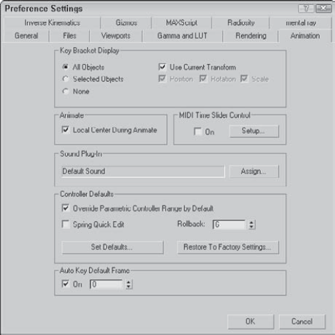
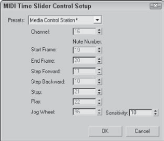
Figure 20.12. The MIDI Time Slider Control Setup dialog box lets you set up specific notes to start, stop, and step through an animation.
You can use the Animation panel to assign a new Sound Plug-In to use, as well as to set the default values of all animation controllers. The Override Parametric Controller Range by Default option causes controllers to be active for the entire animation sequence instead of just their designated range. The Spring Quick Edit option lets you change the accuracy of all Spring controllers in the entire scene in one place. The Rollback setting is the number of frames that the Spring controller uses to return to its original position.
Clicking the Set Defaults button opens the Set Controller Defaults dialog box. This dialog box includes a list of all the controllers and a Set button. When you select a controller and click the Set button, another dialog box appears with all the values for that controller.
When you first start up Max, the default first frame on the Timeline is frame 0, but if you enable the Auto Key Default Frame option, you can set the first frame to be any frame you want. This is convenient if you like to use some frames to set up a shot or if the starting frame of the shot is not at frame 0.
Note
You can learn more about specific controllers in Chapter 21, "Animating with Constraints and Controllers."
Many different objects in Max can be animated, including geometric objects, cameras, lights, and materials. In this section, you'll look at several types of objects and parameters that can be animated.
You can animate cameras using the standard transform buttons found on the main toolbar. When animating a camera that actually moves in the scene, using a Free camera is best. A Target camera can be pointed by moving its target, but you risk it being flipped over if the target is ever directly above the camera. If you want to use a Target camera, attach both the camera and its target to a Dummy object using the Link button and move the Dummy object.
Two useful constraints when animating cameras are the Path constraint and the Look At constraint. You can find both of these in the Animation
Note
For more on constraints, including these two, see Chapter 21, "Animating with Constraints and Controllers."
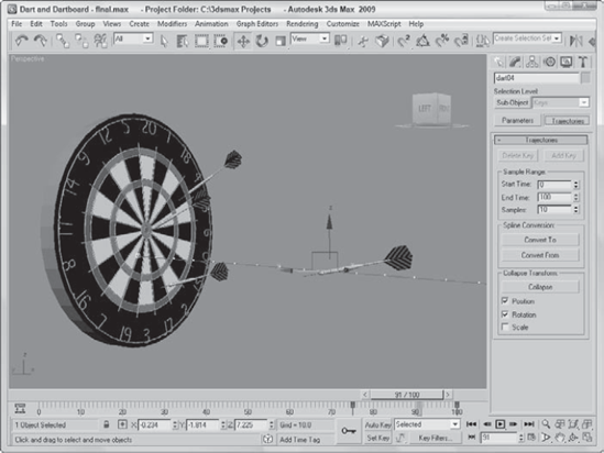
As a simple example of animating objects using the Auto Key button, you'll animate several darts hitting a dartboard.
To animate darts hitting a dartboard, follow these steps:
Open the Dart and dartboard.max file from the Chap 20 directory on the DVD.
This file includes a dart and dartboard objects created by Zygote Media.
Click the Auto Key button (or press the N key) to enable animation mode. Drag the Time Slider to frame 25, and click the Select and Move button on the main toolbar (or press the W key).
Select the first dart in the Left viewport, and drag it to the left until its tip just touches the dartboard.
This step creates a key in the Track Bar for frames 0 and 25.
Click the Select and Rotate button on the main toolbar, set the reference coordinate system to Local, and constrain the rotation to the Y-axis. Then drag the selected dart in the Front viewport to rotate it about its local Y-axis.
This step also sets a key in the Track Bar.
Select the second dart, and click the Select and Move button again. Right-click the Time Slider to make the Create Key dialog box appear. Make sure that the check boxes for Position and Rotation are selected, and click OK.
This step creates a key that keeps the second dart from moving before it's ready.
With the second dart still selected, drag the Time Slider to frame 50 and move the dart to the dartboard as shown in Step 3. Then repeat Step 4 to set the rotation key for the second dart.
Repeat Steps 3, 4, and 5 for the last two darts.
Click the Auto Key button (or press the N key) again to disable animation mode, maximize the Perspective viewport, and click the Play Animation button to see the animation. Figure 20.13 shows the darts as they're flying toward the dartboard.
The process for animating lights includes many of the same techniques as those for animating cameras. For moving lights, use a Free Spot light or attach a Target Spot light to a Dummy object. You can also use the Look At and Path controllers with lights.
Note
If you need to animate the Sun at different times in the day, use the Daylight or Sunlight systems, which are discussed in Chapter 19, "Using Lights and Basic Lighting Techniques."
To flash lights on and off, enable and disable the On parameter at different frames and assign a Step Tangent. To dim lights, just alter the Multiplier value over several frames.
Materials can be animated if their properties are altered while the Auto Key button is active. Max interpolates between the values as the animation progresses. The material must be consistent for the entire animation: You cannot change materials at different keys; you can only alter the existing materials parameters.
If you want to change materials as the animation progresses, you can use a material that combines multiple materials, such as the Blend material. This material includes a Mix Amount value that can change at different keyframes. The next tutorial shows how to use the Blend material in this manner.
Several maps include a Phase value, including all maps that have a Noise rollout. This value provides the means to animate the map. For example, using a Noise map and changing the Phase value over many keys animates the noise effect.
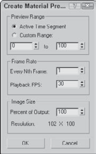
A useful way to view animated materials is to click the Make Preview button (the sixth button from the top) to open the Create Material Preview dialog box, shown in Figure 20.14. Select the Active Time Segment option, and click OK. The material renders every frame and automatically opens and plays the material preview.
Anywhere you can load a bitmap map, you can also load an animation file such as a Microsoft Video (AVI) or a QuickTime (MOV) file. Another way to create animated material is with Image File Lists, which is a text file that lists each separate image file contained in an animation. Max supports two different image file formats—Autodesk ME Image Sequence File (IMSQ) and 3ds Max Image File List (IFL) files.
IMSQ and IFL files are text files that list which images should appear and for which frames. You save them with the .imsq or .ifl extension and load them using the Bitmap map. Image file lists can be created during the render process by selecting the Put Image File List in Output Path option in the Common Parameter rollout of the Render Scene dialog box. There is also a Create Now button to create an image file list at any time.
To manually create an IMSQ or IFL file, open a text editor and type the name of the image followed by the number of frames for which it should appear. Be sure to include a space between the name and the number of frames. The images are displayed in the order they are listed and repeated until all frames have been displayed. Once applied, the image file list is visible in the sample slot if you drag the Time slider, or you can create a material preview.
Note
You can also use the * and ? wildcard characters within an IFL file. For example, flyby* includes any image file that begins with "flyby," and flyby? includes any image file that begins with "flyby" and has one additional character.
If you don't want to create text files by yourself, you can use the IFL Manager Utility to generate IFL files for you. To use this utility, open the Utilities panel and click the More button. Then select the IFL Manager Utility, and click OK.
In the IFL Manager rollout, shown in Figure 20.15, the Select button opens a File dialog box where you can select a sequential list of images to include in an IFL file. After you select a list of images, you can specify the Start and End images. You can cause the images to be displayed in reverse by placing a greater number in the Start field than is in the End field. The Every Nth field can specify to use every Nth image. You use the Multiplier field to specify in how many frames each image should appear.
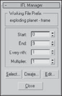
The Create button opens a File dialog box where you can save the IFL file. The Edit button opens an IFL text file in the system's default text editor for editing.
Animated files such as AVI and MOV can be opened and mapped to an object to animate the texture, but you can also use IFL files.
To create an IFL file that will be mapped on the front of a television model, follow these steps:
Open the Windows standard Notepad text editor, and type the following:
; these frames will be positioned on a television screen.
static.tif 20
Exploding planet - frame 10.tif 2
Exploding planet - frame 15.tif 2
Exploding planet - frame 20.tif 2
Exploding planet - frame 25.tif 2
Exploding planet - frame 30.tif 2
Exploding planet - frame 35.tif 2
Exploding planet - frame 40.tif 2
Exploding planet - frame 45.tif 2
Exploding planet - frame 50.tif 2
Exploding planet - frame 55.tif 2
static.tif 60
Save the file as tv.ifl. Make sure that your text editor doesn't add the extension .txt on the end of the file.
You can check your file with the one I created, which you can find in the Chap 20 directory on the DVD.
Note
The IFL file, as described earlier, looks for the image files in the same directory as the IFL file. Make sure that the images are included in this directory.
Open the Television—IFL File.max file from the Chap 20 directory on the DVD.
This file includes a television model created by Zygote Media.
Select the television front screen object, open the Material Editor, and select the first sample slot. Name the material Television Screen. Click the map button to the right of the Diffuse color swatch. Double-click the Bitmap map. In the File dialog box, locate the tv.ifl file and click OK. Then click the Assign Material to Selection button to apply the material to the screen.
Tip
To see the map in the viewport, click the Show Map in Viewport button. This button makes the frames of the IFL file visible in the viewport.
Because the screen object is a mesh object, you need to use the UVW Map modifier to create some mapping coordinates for the map. Open the Modify panel, and select the UVW Map modifier. Set the mapping option to Planar. Then select the Gizmo subobject mode and transform the planar gizmo until it covers the screen.
Click the Play button (/) to see the final animation.
Figure 20.16 shows one rendered frame of the television with the IFL file applied.
More than likely, your final output will be rendered using the highest-quality settings with all effects enabled, and you can count on this taking a fair amount of time. After waiting several days for a sequence to render is a terrible time to find out that your animation keys are off. Even viewing animation sequences in the viewports with the Play Animation button cannot catch all problems.
One way to catch potential problems is to create a sample preview animation. Previews are test animation sequences that render quickly to give you an idea of the final output. The Animation menu includes several commands for creating, renaming, and viewing previews. The rendering options available for previews are the same as the shading options available in the viewports.
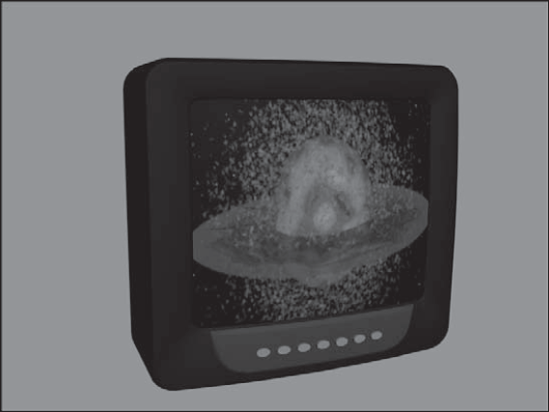
Figure 20.16. IFL files are commonly used to animate materials via a list of images such as the image on the front of this television.
You create previews by choosing Animation
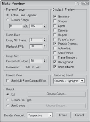
Figure 20.17. The Make Preview dialog box lets you specify the range, size, and output of a preview file.
In the Make Preview dialog box, you can specify what frames to include using the Active Time Segment or Custom Range options. You can also choose Every Nth Frame or select a specific frame rate in the Playback FPS field. The image size is determined by the Percent of Output value, which is a percentage of the final output size. The resolution is also displayed.
The Display in Preview section offers a variety of options to include in the preview. These options include Geometry, Shapes, Lights, Cameras, Helpers, Space Warps, Particle Systems, Active Grid, Safe Frames, Frame Numbers, Background, and Bone Objects. Because the preview output is rendered like the viewports, certain selected objects such as Lights and Cameras actually display their icons as part of the file. The Frame Numbers option prints the frame number in the upper-left corner of each frame.
The Rendering Level drop-down list includes the same shading options used to display objects in the viewports, including Smooth, Smooth + Highlights, Facets, Facets + Highlights, Lit Wireframes, Wireframe, and Bounding Box.
Output options include the default AVI option; a Custom File Type option, which enables you to choose your own format; and the Use Device option, which you can use to render the preview to a different device. For the AVI option, you can select a CODEC, which is used to compress the resulting file. Options include Cinepak Codec by Radius, Logitech Video (1420), Intel IYUV, Microsoft Video 1, Intel Indeo Video 4.5, DivX 5.0.5, and Full Frames (uncompressed), depending on the CODECs that are installed on your system. When the Use Device option is selected, the Choose Device button becomes active. Clicking this button opens the Select Output Image Device dialog box, where you can select and configure output devices such as a Digital Recorder.
At the bottom of the dialog box is a Render Viewport drop-down list, where you can select which viewport to use to create your preview file. The Create button starts the rendering process. When a preview is being rendered, the viewports are replaced with a single image of the current render frame, and the Status bar is replaced by a Progress bar and a Cancel button.
Tip
You can use the Esc key on your keyboard to cancel a rendering job.
If you cancel the rendering, the Make Preview alert box offers the options Stop and Play; Stop and Don't Play; and Don't Stop.
When a preview file is finished rendering, the default Media Player for your system loads and displays the preview file. You can disable this autoplay feature using the Autoplay Preview File option in the General panel of the Preference Settings dialog box.
At any time, you can replay the preview file using the Animation
This chapter covered the basics of animating objects in Max, including working with time and keys. You also learned about the two key creation modes and editing keys. Several animation helps are available, such as trajectories and ghosting. This chapter also discussed how to animate materials and how to create preview animations. In this chapter, you learned how to do the following:
Control time and work with keys
Use the two key creation modes
Work with the Track Bar and the Motion panel
View and edit key values
Use trajectories and ghosting
Animate materials and use IFL files
Create preview animations
The next chapter shows how to automate the creation of animation keys with constraints and controllers.