
Many modeling projects start from the ground up, and you can't get much lower to the ground than 2D. But this book is on 3D, you say? What place is there for 2D shapes? Within the 3D world, you frequently encounter flat surfaces—the side of a building, the top of a table, a billboard, and so on. All these objects have flat 2D surfaces. Understanding how objects are composed of 2D surfaces will help as you start to build objects in 3D. This chapter examines the 2D elements of 3D objects and covers the tools needed to work with them.
Working in 2D in Max, you use two general objects: splines and shapes. A spline is a special type of line that curves according to mathematical principles. In Max, splines are used to create all sorts of shapes such as circles, ellipses, and rectangles.
You can create splines and shapes using the Create
Shapes in Max are unique from other objects because they are drawn in 2D, which confines them to a single plane. That plane is defined by the viewport used to create the shape. For example, drawing a shape in the Top view constrains the shape to the XY plane, whereas drawing the shape in the Front view constrains it to the ZX plane. Even shapes drawn in the Perspective view are constrained to a plane such as the Home Grid.
You usually produce 2D shapes in a drawing package such as Adobe Illustrator (AI) or CorelDRAW. Max supports importing line drawings using the AI format.
Note
See Chapter 3, "Working with Files, Importing, and Exporting," to learn about importing AI files.
Whereas newly created or imported shapes are 2D and are confined to a single plane, splines can exist in 3D space. The Helix spline, for example, exists in 3D, having height as well as width values. Animation paths in particular typically move into 3D space.
The shape primitive buttons are displayed in the Object Type rollout of the Create panel when either the Create
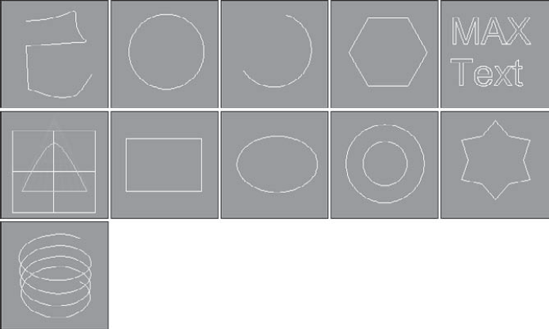
Figure 12.1. The shape primitives in all their 2D glory: Line, Circle, Arc, NGon, Text, Section, Rectangle, Ellipse, Donut, Star, and Helix
Above the Shape buttons are two check boxes: AutoGrid and Start New Shape. AutoGrid creates a temporary grid, which you can use to align the shape with the surface of the nearest object under the mouse at the time of creation. This feature is helpful for starting a new spline on the surface of an object.
Note
For more details on AutoGrid, see Chapter 7, "Transforming Objects, Pivoting, Aligning, and Snapping."

The Start New Shape option creates a new object with every new shape drawn in a viewport. Leaving this option unchecked lets you create compound shapes, which consist of several shapes used to create one object. Because compound shapes consist of several shapes, the shapes are automatically converted to be an Editable Spline object and you cannot edit them using the Parameters rollout. For example, if you want to create a target from several concentric circles, keep the Start New Shape option unselected to make all the circles part of the same object.
Just as with the Geometric primitives, every shape that is created is given a name and a color. You can change either of these in the Name and Color rollout.
Most of the shape primitives have several common rollouts: Rendering, Interpolation, Creation Method, Keyboard Entry, and Parameters, as shown in Figure 12.3. I cover these rollouts initially and then present the individual shape primitives.
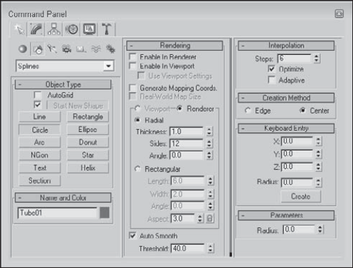
The Rendering rollout includes options for making a spline a renderable object. Making a spline a renderable object converts the spline into a 3D object that is visible when you render the scene. For renderable objects, you can choose to make the spline Radial or Rectangular. For the Radial option, you can specify a Thickness, the number of Sides, and the Angle values; for the Rectangular option, you can specify Length, Width, Angle, and Aspect values.
The Radial Thickness is the diameter of the renderable spline. The number of Sides sets the number of sides that make up the cross section of the renderable spline. The lowest value possible is 3, which creates a triangle cross section. The Length and Width values set the size along the Y-axis and the X-axis, respectively, of the rectangular sides. The Angle value determines where the corners of the cross section sides start, so you can set a three-sided spline to have a corner or an edge pointing upward. The Aspect value sets the ratio of the Length per Width. If the Lock icon to the right of the Aspect value is enabled, then the aspect ratio is locked, and changing one value affects the other.
Note
By default, a renderable spline has a 12-sided circle as its cross section.
You can choose different rendering values for the viewport and for the renderer using the Viewport and Renderer options above the Radial option. Each of these settings can be enabled or disabled using the Enable in Renderer and Enable in Viewport options at the top of the Rendering rollout. Renderable splines appear as normal splines in the viewport unless the Enable in Viewport option is selected. The Use Viewport Settings option gives the option of setting the spline render properties different in the viewport and the renderer.
The Auto Smooth option and Threshold value offer a way to smooth edges on the renderable spline. If the angle between two adjacent polygons is less than the Threshold value, then the edge between them is smoothed. If it is greater than the Threshold value, then the hard edge is preserved.
The Generate Mapping Coordinates option automatically generates mapping coordinates that are used to mark where a material map is placed, and the Real-World Map Size option allows real-world scaling to be used when mapping a texture onto the renderable spline.
Note
To learn more about mapping coordinates and real-world scaling, see Chapter 17, "Adding Material Details with Maps."
In the Interpolation rollout, you can define the number of interpolation steps or segments that make up the shape. The Steps value determines the number of segments to include between adjacent vertices. For example, a circle shape with a Steps value of 0 has only four segments and looks like a diamond. Increasing the Steps value to 1 makes a circle out of eight segments. For shapes composed of straight lines (like the Rectangle and simple NGons), the Steps value is set to 0, but for a shape with many sides (like a Circle or Ellipse), the Steps value can have a big effect. Larger step values result in smoother curves.
The Adaptive option automatically sets the number of steps to produce a smooth curve by adding more interpolation points to the spline based on the spline's curvature. When the Adaptive option is enabled, the Steps and Optimize options become disabled. The Optimize option attempts to reduce the number of steps to produce a simpler spline by eliminating all the extra segments associated with the shape.
Note
The Section and Helix shape primitives have no Interpolation rollout.
Figure 12.4 shows the number 5 drawn with the Line primitive in the Front viewport. The line has been made renderable so that you can see the cross sections. The images from left to right show the line with Steps values of 0, 1, and 3. The fourth image has the Optimize option enabled. Notice that it uses only one segment for the straight edges. The fifth image has the Adaptive option enabled.

Most shape primitives also include Creation Method and Keyboard Entry rollouts (Text, Section, and Star are the exceptions). The Creation Method rollout offers options for specifying different ways to create the spline by dragging in a viewport, such as from edge to edge or from the center out. Table 12.1 lists the various creation method options for each of the shapes and each of the extended shapes.
Table 12.1. Shape Primitive Creation Methods
Primitive Object | Number of Viewport Clicks to Create | Default Creation Method | Other Creation Method |
|---|---|---|---|
Line | 2 to Infinite | Corner Initial, Bézier Drag | Smooth, Initial, Corner, or Smooth Drag |
Circle | 1 | Center | Edge |
Arc | 2 | End-End-Middle | Center-End-End |
NGon | 1 | Center | Edge |
Text | 1 | none | none |
Section | 1 | none | none |
Rectangle | 1 | Edge | Center |
Ellipse | 1 | Edge | Center |
Donut | Center | Edge | |
Star | 2 | none | none |
Helix | 3 | Center | Edge |
WRectangle | 2 | Edge | Center |
Channel | 2 | Edge | Center |
Angle | 2 | Edge | Center |
Tee | 2 | Edge | Center |
Wide Flange | 2 | Edge | Center |
Some shape primitives such as Star, Text, and Section don't have any creation methods because Max offers only a single way to create these shapes.
The Keyboard Entry rollout offers a way to enter exact position and dimension values. After you enter the values, click the Create button to create the spline or shape in the active viewport. The settings are different for each shape.
The Parameters rollout includes such basic settings for the primitive as Radius, Length, and Width. You can alter these settings immediately after an object is created. However, after you deselect an object, the Parameters rollout moves to the Modify panel, and you must do any alterations to the shape there.
The Line primitive includes several creation method settings, enabling you to create hard, sharp corners or smooth corners. You can set the Initial Type option to either Corner or Smooth to create a sharp or smooth corner for the first point created.
After clicking where the initial point is located, you can add points by clicking in the viewport. Dragging while creating a new point can make a point a Corner, Smooth, or Bézier based on the Drag Type option selected in the Creation Method rollout. The curvature created by the Smooth option is determined by the distance between adjacent vertices, whereas you can control the curvature created by the Bézier option by dragging with the mouse a desired distance after the point is created. Bézier corners have control handles associated with them, enabling you to change their curvature.
Tip
Holding down the Shift key while clicking creates points that are constrained vertically or horizontally. This makes it easy to create straight lines that are at right angles to each other. Holding down the Ctrl key snaps new points at an angle from the last segment, as determined by the Angle Snap setting.
After creating all the points, you exit line mode by clicking the right mouse button. If the last point is on top of the first point, then a dialog box asks whether you want to close the spline. Click Yes to create a closed spline or No to continue adding points. Even after creating a closed spline, you can add more points to the current selection to create a compound shape if the Start New Shape option isn't selected. If the first and last points don't correspond, then an open spline is created.
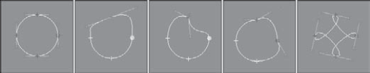
Figure 12.5 shows several splines created using the various creation method settings. The left spline was created with all the options set to Corner, and the second spline with all the options set to Smooth. The third spline uses the Corner Initial type and shows where dragging has smoothed many of the points. The last spline was created using the Bézier option.

Figure 12.5. The Line shape can create various combinations of shapes with smooth and sharp corners.
In the Keyboard Entry rollout, you can add points by entering their X, Y, and Z dimensions and clicking the Add Point button. You can close the spline at any time by clicking the Close button or keep it open by clicking the Finish button.
The Rectangle shape produces simple rectangles. In the Parameters rollout, you can specify the Length and Width and also a Corner Radius. Holding down the Ctrl key while dragging creates a perfect square shape.
The Circle button creates—you guessed it—circles. The only adjustable parameter in the Parameters rollout is the Radius. All other rollouts are the same, as explained earlier. Circles created with the Circle button have only four vertices.
Ellipses are simple variations of the Circle shape. You define them by Length and Width values. Holding down the Ctrl key while dragging creates a perfect circle (or you can use the Circle shape).
The Arc primitive has two creation methods. Use the End-End-Middle method to create an arc shape by clicking and dragging to specify the two end points and then dragging to complete the shape. Use the Center-End-End method to create an arc shape by clicking and dragging from the center to one of the end points and then dragging the arc length to the second end point.
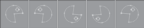
Other parameters include the Radius and the From and To settings, where you can enter the value in degrees for the start and end of the arc. The Pie Slice option connects the end points of the arc to its center to create a pie-sliced shape, as shown in Figure 12.6. The Reverse option lets you reverse the arc's direction.

As another variation of the Circle shape, the Donut shape consists of two concentric circles; you can create it by dragging once to specify the outer circle and again to specify the inner circle. The parameters for this object are simply two radii.
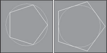
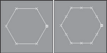
The NGon shape lets you create regular polygons by specifying the Number of Sides and the Corner Radius. You can also specify whether the NGon is Inscribed or Circumscribed, as shown in Figure 12.7. Inscribed polygons are positioned within a circle that touches all the outer polygon's vertices. Circumscribed polygons are positioned outside of a circle that touches the midpoint of each polygon edge. The Circular option changes the polygon to a circle that inscribes the polygon.
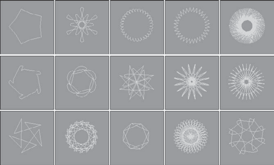
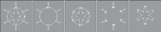
The Star shape also includes two radii values—the larger Radius value defines the distance of the outer points of the Star shape from its center, and the smaller Radius value is the distance from the center of the star to the inner points. The Point setting indicates the number of points. This value can range from 3 to 100. The Distortion value causes the inner points to rotate relative to the outer points and can be used to create some interesting new star types. The Fillet Radius 1 and Fillet Radius 2 values adjust the Fillet for the inner and outer points. Figure 12.8 shows a sampling of what is possible with the Star shapes.
You can use the Text primitive to add outlined text to the scene. In the Parameters rollout, you can specify a Font by choosing one from the drop-down list at the top of the Parameters rollout. Under the Font drop-down list are six icons, shown in Table 12.2. The left two icons are for the Italic and Underline styles. Selecting either of these styles applies the style to all the text. The right four icons are for aligning the text to the left, centered, right, or justified.
Note
The list of available fonts includes only the Windows TrueType fonts and Type 1 PostScript fonts installed on your system and any extra fonts located in the font path listed in the Configure Paths dialog box. You need to restart Max before the fonts in the font path are recognized.
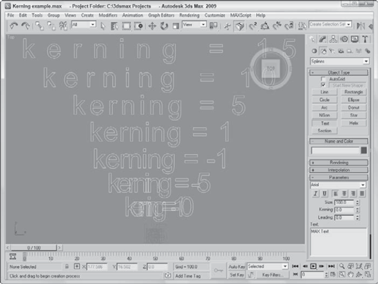
The size of the text is determined by the Size value. The Kerning (which is the space between adjacent characters) and Leading (which is the space between adjacent lines of text) values can actually be negative. Setting the Kerning value to a large negative number actually displays the text backwards. Figure 12.9 shows an example of some text and an example of kerning values in the Max interface.
You can type the text to be created in the text area. You can cut, copy, and paste text into this text area from an external application if you right-click on the text area. After setting the parameters and typing the text, the text appears as soon as you click in one of the viewports. The Text is updated automatically when any of the parameters (including the text) are changed. To turn off automatic updating, select the Manual Update toggle. You can then update with the Update button.
To enter special characters into the text area, hold down the Alt key while typing the character code using the numeric keypad. For example, type 0188 in the numeric keypad with the Alt key held down and the ¼ symbol appears. If you open the Character Map application, you can see a complete list of special characters and the number combinations that make them appear. The Character Map application, shown in Figure 12.10, can be opened in Windows by selecting Start

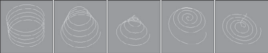
A Helix is like a spring coil shape, and it is the one shape of all the Shape primitives that exists in 3D. Helix parameters include two radii for specifying the inner and outer radius. These two values can be equal to create a coil or unequal to create a spiral. Parameters also exist for the Height and number of Turns. The Bias parameter causes the Helix turns to be gathered all together at the top or bottom of the shape. The CW and CCW options let you specify whether the Helix turns clockwise or counterclockwise.
Figure 12.11 shows a sampling of Helix shapes: The first Helix has equal radii values, the second one has a smaller second radius, the third Helix spirals to a second radius value of 0, and the last two Helix objects have Bias values of 0.8 and −0.8.
Section stands for cross section. The Section shape is a cross section of the edges of any 3D object through which the Section's cutting plane passes. The process consists of dragging in the viewport to create a cross-sectioning plane. You can then move, rotate, or scale the cross-sectioning plane to obtain the desired cross section. In the Section Parameters rollout is a Create Shape button. Clicking this button opens a dialog box where you can name the new shape. You can use one Section object to create multiple shapes.
Note
You can make sections only from intersecting a 3D object. If the cross-sectioning plane doesn't intersect the 3D object, then it won't create a shape. You cannot use the Section primitive on shapes, even if it is a renderable spline.
The Parameters rollout includes settings for updating the Section shape. You can update it when the Section plane moves, when the Section is selected, or Manually (using the Update Section button). You can also set the Section Extents to Infinite, Section Boundary, or Off. The Infinite setting creates the cross-section spline as if the cross-sectioning plane were of infinite size, whereas the Section Boundary limits the plane's extents to the boundaries of the visible plane. The color swatch determines the color of the intersecting shape.
To give you an idea of what the Section shape can produce, Figure 12.12 shows the shapes resulting from sectioning two Cone objects, including a circle, an ellipse, a parabola, and a hyperbole. The shapes have been moved to the sides to be more visible.
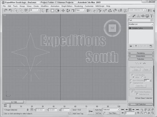
One of the early uses for 3D graphics was to animate corporate logos, and although Max can still do this without any problems, it now has capabilities far beyond those available in the early days. The Shape tools can even be used to design the logo. In this example, you'll design and create a simple logo using the Shape tools for the fictitious company named Expeditions South.
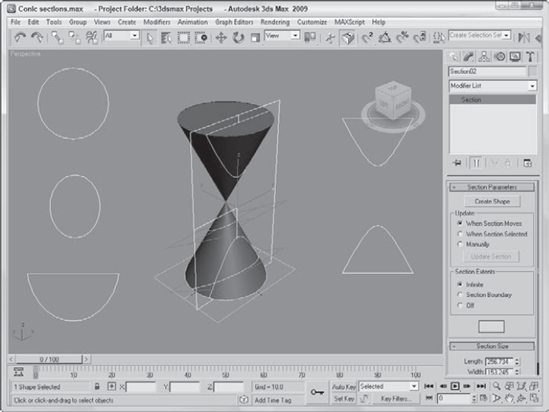
Figure 12.12. You can use the Section shape primitive to create the conic sections (circle, ellipse, parabola, hyperbola) from a set of 3D cones.
To use the Shape tools to design and create a company logo, follow these steps:
Create a four-pointed star by clicking the Star button and dragging in the Top view to create a shape. Change the parameters for this star as follows: Radius1 = 60, Radius2 = 20, and Points = 4.
Select and move the star shape to the left side of the viewport.
Now click the Text button, and change the font to Impact and the Size to 50. In the Text area, type Expeditions South and include a line return and several spaces between the two words so they are offset. Click in the Top viewport to place the text.
Use the Select and Move button (W) to reposition the text next to the Star shape.
Click the Line button, and create several short highlighting lines around the bottom point of the star.
The finished logo is now ready to extrude and animate. Figure 12.13 shows the results.
As an example of the Section primitive, you'll explore a section of a Heart model. The model was created by Viewpoint Datalabs and is very realistic—so realistic, in fact, that it could be used to teach medical students the inner workings of the heart.
To create a spline from the cross section of the heart, follow these steps:
Open the Heart section.max file from the Chap 12 directory on the DVD.
This file includes a physical model of a heart created by Viewpoint Datalabs.
Select Create

This plane is your cross-sectioning plane.
Select the Select and Rotate button on the main toolbar (or press the E key), and rotate the cross-sectioning plane to cross the heart at the desired angle.
In the Parameters rollout of the Modify panel, click the Create Shape button and give the new shape the name Heart Section.
From the Select by Name dialog box (opened with the H key), select the section by name, separate it from the model, and reposition it to be visible.
Figure 12.14 shows the resulting model and section.

After you create a shape primitive, you can edit it by modifying its parameters, but the parameters for shapes are fairly limited. For example, the only parameter for the Circle shape is Radius. All shapes can be converted to Editable Splines, or they can have the Edit Spline modifier applied to them. Doing either enables a host of editing features. Before you can use these editing features, you must convert the shape primitive to an Editable Spline (except for the Line shape). You can do so by right-clicking the spline shape in the viewport and choosing Convert to
After you convert the spline to an Editable Spline, you can edit individual subobjects within the spline, including Vertices, Segments, and Splines. There is a subtle difference between applying the Edit Spline modifier and converting the shape to an Editable Spline. Applying the Edit Spline modifier maintains the shape parameters and enables the editing features found in the Geometry rollout. However, an Editable Spline loses the ability to be able to change the base parameters associated with the spline shape.
Note
When you create an object that contains two or more splines (such as when you create splines with the Start New Shape option disabled), all the splines in the object are automatically converted into Editable Splines.
Another difference is that the shape primitive base name is listed along with the Edit Spline modifier in the Modifier Stack. Selecting the shape primitive name makes the Rendering, Interpolation, and Parameters rollouts visible, and the Selection, Soft Selection, and Geometry rollouts are made visible when you select the Edit Spline modifier in the Modifier Stack. For Editable Splines, only a single base object name is visible in the Modifier Stack, and all rollouts are accessible under it.
Note
Another key difference is that subobjects for the Edit Spline modifier cannot be animated.
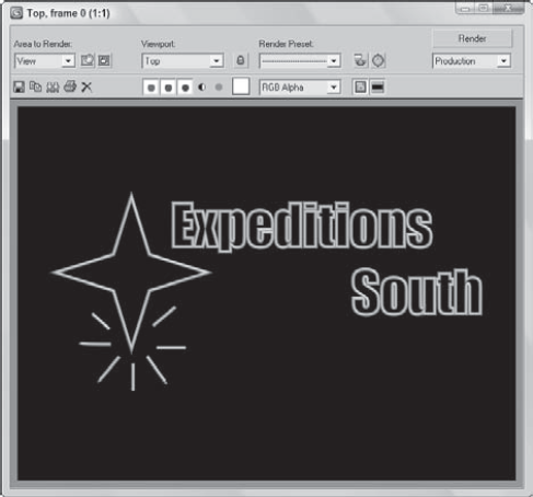
Splines normally do not show up in a rendered image, but using the Renderable option in the Rendering rollout and assigning a thickness to the splines makes them appear in the rendered image. Figure 12.15 shows a rendered image of the Expeditions South logo after all shapes have been made renderable and assigned a Thickness of 3.0.
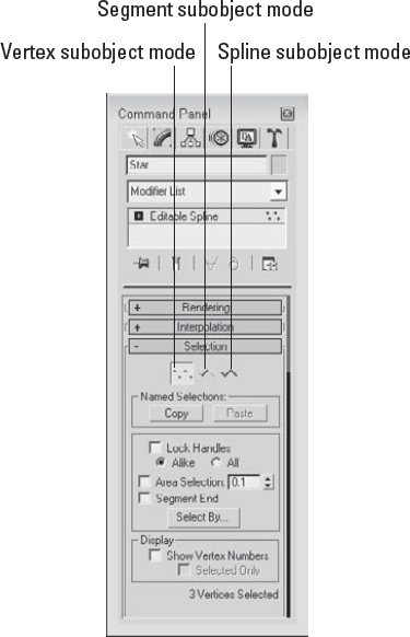
When editing splines, you must choose the subobject level to work on. For example, when editing splines, you can work with Vertex (1), Segment (2), or Spline (3) subobjects. Before you can edit spline subobjects, you must select them. To select the subobject type, click the small plus sign icon to the left of the Editable Spline object in the Modifier Stack. This lists all the subobjects available for this object. Click the subobject in the Modifier Stack to select it. Alternatively, you can click the red-colored icons under the Selection rollout, shown in Figure 12.16. You can also select the different subobject modes using the 1, 2, and 3 keyboard shortcuts. When you select a subobject, the selection in the Modifier Stack and the associated icon in the Selection rollout turn yellow.
Note
The Sub-Object button turns yellow when selected to remind you that you are in subobject edit mode. Remember, you must exit this mode before you can select another object.
You can select many subobjects at once by dragging an outline over them in the viewports. You can also select and deselect vertices by holding down the Ctrl key while clicking them. Holding down the Alt key removes any selected vertices from the selection set.
After selecting several vertices, you can create a named selection set by typing a name in the Name Selection Sets drop-down list in the main toolbar. You can then copy and paste these selection sets onto other shapes using the buttons in the Selection rollout.
The Lock Handles option allows you to move the handles of all selected vertices together when enabled, but each handle moves by itself when disabled. With the Lock Handles and the All options selected, all selected handles move together. The Alike option causes all handles on one side to move together.
The Area Selection option selects all the vertices within a defined radius of where you click. The Segment End option, when enabled, allows you to select a vertex by clicking the segment. The closest vertex to the segment that you clicked is selected. This feature is useful when you are trying to select a vertex that lies near other vertices. The Select By button opens a dialog box with Segment and Spline buttons on it. These buttons allow you to select all the vertices on either a spline or segment that you choose.
The Selection rollout also has the Show Vertex Numbers option to display all the vertex numbers of a spline or to show the numbers of only the selected vertices. This can be convenient for understanding how a spline is put together and to help you find noncritical vertices. The Selected Only option displays the Vertex Numbers only for the selected subobjects when enabled.
Note
The vertex order is critical in determining the direction in which cross sections are swept when using the Loft and Sweep commands. You always can identify the first vertex in a spline because it is yellow.
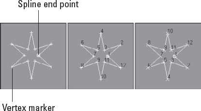
Figure 12.17 shows a simple star shape that was converted to an Editable Spline. The left image shows the spline in Vertex subobject mode. All the vertices are marked with small plus signs, and the starting point is marked with a small square. The middle image has the Show Vertex Numbers option enabled. For the right image, the vertex numbers are shown after the Reverse button was used (in Spline subobject mode).
At the bottom of the Selection rollout, the Selection Information is displayed. This information tells you the number of the spline (or segment) and vertex selected, or the number of selected items and whether a spline is closed.
Note
The Soft Selection rollout allows you to alter adjacent non-selected subobjects (to a lesser extent) when selected subobjects are moved, creating a smooth transition. See Chapter 10, "Learning Modeling Basics and Working with Subobjects and Helpers," for the details on this rollout.
Much of the power of editing splines is contained within the Geometry rollout, shown in Figure 12.18, including the ability to add new splines, attach objects to the spline, weld vertices, use Boolean operations such as Trim and Extend, and many more. Some Geometry buttons may be disabled, depending on the subobject type that you've selected. Many of the features in the Geometry rollout can be used in all subobject modes. Some of these features do not even require that you be in a subobject mode. These features are covered first.
Tip
The quadmenu provides quick access to the main features for each subobject mode. After you are familiar with the various features, you can quickly access them through the quadmenu by simply right-clicking in the viewport.
While editing splines, you can add new lines to a spline by clicking the Create Line button and then clicking in the one of the viewports. You can add several lines at the same time and all these new splines are part of the same object. Right-click in the viewport to exit this mode. Any new lines are their own spline, but you can weld them to the existing splines.
Selecting a vertex and clicking the Break button in Vertex subobject mode breaks the segment at the selected vertex by creating two separate end points. You also can use the Break button in Segment subobject mode by clicking anywhere along the segment to add two separated vertices on the segment, thereby breaking the segment into two. You can also use the Break button in Vertex and Segment subobject modes.
The Attach button lets you attach any existing splines to the currently selected spline. The cursor changes when you're over the top of a spline that can be attached. Clicking an unselected object makes it part of the current object. The Reorient option aligns the coordinate system of the spline being attached with the selected spline's coordinate system.

For example, using the Boolean button requires that objects be part of the same object. You can use the Attach button to attach several splines into the same object.
The Attach Mult. button enables several splines to be attached at once. When you click the Attach Mult. button, the Attach Multiple dialog box (which looks much like the Select by Name dialog box) opens. Use this dialog box to select the objects you want to attach to the current selection. Click the Attach button in the dialog box when you're finished. You can use both the Attach and Attach Mult. buttons in all three subobject modes.
Note
If the spline object that is being attached has a material applied to it, then a dialog box appears that gives you options for handling the materials. These options include Match Material IDs to Material, Match Material to Material IDs, or Do Not Modify Material IDs or Material. Applying materials is covered in Chapter 14, "Exploring the Material Editor."
The Cross Section button works just like the Cross Section modifier by creating splines that run from one cross-section shape to another. For example, imagine creating a baseball bat by positioning circular cross sections for each diameter change and connecting each cross section from one end to the other. All the cross sections need to be part of the same Editable Spline object, and then using the Cross Section button, you can click from one cross section to another. The cursor changes when the mouse is over a shape that can be used. When you're finished selecting cross-section shapes, you can right-click to exit Cross Section mode.
The type of vertex used to create the new splines that run between the different cross sections is the type specified in the New Vertex Type section at the top of the Geometry rollout.
Warning
Although the splines that connect the cross sections are positioned alongside the cross section shape, they are not connected.
After the splines are created, you can use the Surface modifier to turn the splines into a 3D surface.
To work with surfaces, you typically need a closed spline. When you enable the Automatic Welding option in the End Point Auto-Welding section and specify a Threshold, all end points within the threshold value are welded together, thus making a closed spline.
The Insert button adds vertices to a selected spline. Click the Insert button, and then click the spline to place the new vertex. At this point, you can reposition the new vertex and its attached segments—click again to set it in place. A single click adds a Corner type vertex, and a click-and-drag adds a Bézier type vertex.
After positioning the new vertex, you can add another vertex next to the first vertex by dragging the mouse and clicking. To add vertices to a different segment, right-click to release the currently selected segment, but stay in Insert mode. To exit Insert mode, right-click in the viewport again or click the Insert button to deselect it.
You can work with cross sections in several ways. You can use the Cross Section feature for Editable Splines, the Cross Section modifier, or the Loft compound object. All these methods have advantages, but the first is probably the easiest and most forgiving method.
To create a simple doorknob using the Editable Spline Cross Section button, follow these steps:
Right-click any of the Snap toggle buttons on the main toolbar, and select Grid Points in the Grid and Snap Settings dialog box. Then click the Snap toggle button on the main toolbar (or press the S key) to enable grid snapping.
Select the Create
Select the Create
Click the Select and Move (W) button on the main toolbar, and drag the shapes in the Left viewport upward in this order: square, square, small circle, large circle, small circle. Separate the squares by a distance equal to the width of a door, and spread the circles out to be the width of a doorknob.
Select the bottom-most square shape, and then right-click and select Convert To
In the Geometry rollout, click the Attach button and then select the other shapes to add them to the selected Editable Spline object.
Rotate the Perspective viewport until all shapes are visible and easily selectable. Then select each and rotate each of the cross sections in the Top viewport so their first vertices are aligned. This helps prevent any twisting that may occur when the cross sections try to align the first vertices.
Select the Linear option in the New Vertex Type section in the Geometry rollout, and then click the Cross Section button. Click the lowest square shape in the Perspective viewport, followed by the higher square shape, and then the lower small circle. This creates a spline that runs linearly between these lowest three cross-section shapes. Right-click in the Perspective viewport to exit Cross Section mode.
Select the Bezier option in the New Vertex Type section, and then click the Cross Section button again. Click the lowest circle shape in the Perspective viewport, followed by the larger circle shape, and then the higher small circle. This creates a spline that runs smoothly between the last three cross-section shapes. Right-click in the Perspective viewport to exit Cross Section mode.
Tip
Once a spline outline is constructed, you can use the Surface modifier to add a surface to the object.
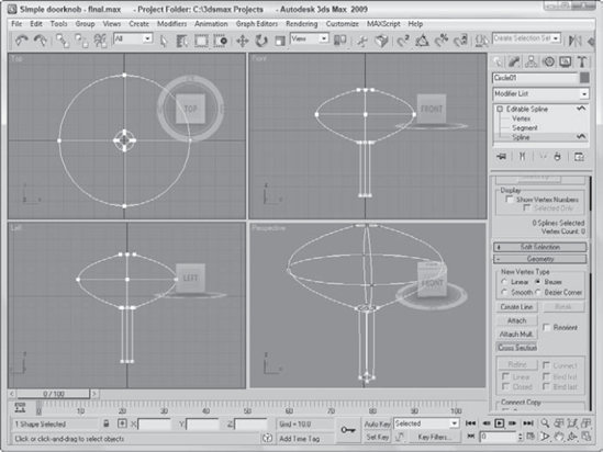
Figure 12.19 shows the splines running between the different cross sections. A key benefit to the Editable Spline approach is that you don't need to order the cross-section shapes exactly. You just need to click on them in the order that you want.
To edit a vertex, click the Vertex subobject in the Modifier Stack or select the vertex icon from the Selection rollout (keyboard shortcut, 1). After the Vertex subobject type is selected, you can use the transform buttons on the main toolbar to move, rotate, and scale the selected vertex or vertices. Moving a vertex around causes the associated spline segments to follow.
With a vertex selected, you can change its type from Corner, Smooth, Bézier, or Bézier Corner by right-clicking and selecting the type from the pop-up quadmenu.
Warning
The New Vertex Type section in the top of the Geometry sets only the vertex type for new vertices created when you Shift-copy segments and splines or new vertices created with the Cross Section button. These options cannot be used to change vertex type for existing vertices.
Selecting the Bézier or Bézier Corner type vertex reveals green-colored handles on either side of the vertex. Dragging these handles away from the vertex alters the curvature of the segment. Bézier type vertices have both handles in the same line, but Corner Bézier type vertices do not. This allows them to create sharp angles.
Note
Holding down the Shift key while clicking and dragging on a handle causes the handle to move independently of the other handle, turning it into a Bézier Corner type vertex instead of a plain Bézier. You can use it to create sharp corner points.
Figure 12.20 shows how the Bézier and Bézier Corner handles work. The first image shows all vertices of a circle selected where you can see the handles protruding from both sides of each vertex. The second image shows what happens to the circle when one of the handles is moved. The handles for Bézier vertices move together, so moving one upward causes the other to move downward. The third image shows a Bézier Corner vertex where the handles can move independently to create sharp points. The fourth image shows two Bézier Corner vertices moved with the Lock Handles and Alike options enabled. This causes the handles to the left of the vertices to move together. The final image has the Lock Handles and All options selected, causing the handles of all selected vertices to move together.
The pop-up quadmenu also includes a command to Reset Tangents. This option makes the tangents revert to their original orientation before the handles were moved.
The Refine button lets you add vertices to a spline without changing the curvature, giving you more control over the details of the spline. With the Refine button selected, just click on a spline where you want the new vertex and one is added.
The Connect option adds a new segment that connects each two successive points added with the Refine tool. These segments don't actually appear until the Refine button is disabled. This provides a method for copying part of an existing spline. When the Connect option is enabled, then the Linear, Closed, Bind First, and Bind Last options become enabled. The Linear option creates Corner type vertices resulting in linear segments. The Closed option closes the spline by connecting the first and last vertices. The Bind First and Bind Last options bind the first and last vertices to the center of the selected segment. Refine is available only for Vertex and Segment subobject modes.
When two endpoint vertices are selected and are within the specified Weld Threshold, they can be welded into one vertex and moved to a position that is the average of the welded points using the Weld button. Several vertices can be welded simultaneously. Another way to weld vertices is to move one vertex on top of another. If they are within the threshold distance, a dialog box asks whether you want them to be welded. Click the Yes button to weld them.
Warning
The Weld button can be used only to weld spline endpoints.
The Fuse button is similar to the Weld command, except that it doesn't delete any vertices. It just positions the two vertices on top of one another at a position that is the average of the selected vertices.
In Figure 12.21, the left image shows a star shape with all its lower vertices selected. The middle image is the same star shape after the selected vertices have been welded together, and the right image shows the star shape with the selected vertices fused. The Selection rollout shows five selected vertices for the fused version.
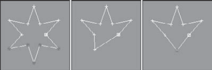
Figure 12.21. Using the Fuse and Weld buttons, several vertices in the star shape have been combined.
You can use the Fuse button to move the selected vertices to a single location. This is accomplished by selecting all the vertices to relocate and clicking the Fuse button. The average point between all the selected vertices becomes the new location. You can combine these vertices into one after they've been fused by clicking the Weld button.
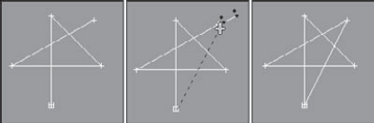
The Connect button lets you connect end vertices to one another to create a new line. This works only on end vertices, not on connected points within a spline. To connect the ends, click the Connect button and drag the cursor from one end point to another (the cursor changes to a plus sign when it is over a valid end point) and release it. The first image in Figure 12.22 shows an incomplete star drawn with the Line primitive, the middle image shows a line being drawn between the end points (notice the cursor), and the third image is the resulting star.
The Show Vertex Numbers option in the Selection rollout displays the number of each vertex. The first vertex is identified by the yellow color. The Make First button lets you change which vertex you want to be the first vertex in the spline. To do this, select a single vertex and click the Make First button. If more than one vertex is selected, Max ignores the command. If the selected spline is an open spline, again Max ignores the command; an end point must be selected.
Note
The vertex number is important because it determines the first key for path animations and where Loft objects start.
If a single vertex is selected, the Cycle button causes the next vertex in the Vertex Number order to be selected. The Cycle button can be used on open and closed splines and can be repeated around the spline. The exact vertex number is shown at the bottom of the Selection rollout. This is very useful for locating individual vertices in groups that are close together, such as groups that have been fused.
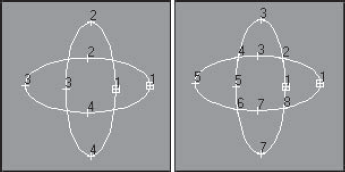
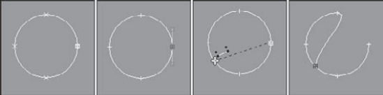
If two splines that are part of the same object overlap, you can use the CrossInsert button to create a vertex on each spline at the location where they intersect. The distance between the two splines must be closer than the Threshold value for this to work. Note that this button does not join the two splines; it only creates a vertex on each spline. Use the Weld button to join the splines. Figure 12.23 shows how you can use the CrossInsert button to add vertices at the intersection points of two elliptical splines. Notice that each ellipse now has eight vertices.
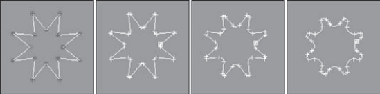
The Fillet button is used to round the corners of a spline where two edges meet. To use the Fillet command, click the Fillet button and then drag on a corner vertex in the viewport. The more you drag, the larger the Fillet. You can also enter a Fillet value in the Fillet spinner for the vertices that are selected. The Fillet has a maximum value based on the geometry of the spline. Figure 12.24 shows the Fillet command applied to an eight-pointed star with values of 10, 15, and 20. Notice that each selected vertex has split into two.
Warning
Be careful not to apply the fillet command multiple times to the selected vertices. If the new vertices cross over each other, then the normals will be misaligned, which will cause problems when you use modifiers.
Note
You can fillet several vertices at once by selecting them and then clicking the Fillet button and dragging the Fillet distance.
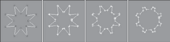
The Chamfer button works much like the Fillet button, except that the corners are replaced with straight-line segments instead of smooth curves. This keeps the resulting shape simpler and maintains hard corners. To use the Chamfer command, click the Chamfer button and drag on a vertex to create the Chamfer. You can also enter a Chamfer value in the rollout. Figure 12.25 shows chamfers applied to the same eight-pointed shape with the same values of 10, 15, and 20.
If you spend considerable time positioning the handles for the Bézier or Bézier Corner vertices just right, it can be tricky to repeat these precise positions again for other handles. Using the Tangent Copy and Tangent Paste buttons, you can copy the handle positions between different handles. To do so, simply select a handle that you wish to copy and click the Copy button, and then select the vertex to which you want to copy the handle and press the Paste button. The Paste Length button copies the handle length along with its orientation, if enabled.
The Hide and Unhide All buttons hide and unhide spline subobjects. They can be used in any subobject mode. To hide a subobject, select the subobject and click the Hide button. To unhide the hidden subobjects, click the Unhide All button.
The Bind button attaches an end vertex to a segment. The bound vertex then cannot be moved independently, but only as part of the bound segment. The Unbind button removes the binding on the vertex and lets it move independently again. To bind a vertex, click the Bind button and then drag from the vertex to the segment to bind to. To exit Bind mode, right-click in the viewport or click the Bind button again.
For Figure 12.26, a circle shape is created and converted to an Editable Spline object. The right vertex is selected and then separated from the circle with the Break button. Then by clicking the Bind button and dragging the vertex to the opposite line segment, the vertex is bound to the segment. Any movement of the spline keeps this vertex bound to the segment.
The Delete button deletes the selected subobject. You can use it to delete vertices, segments, or splines. This button is available in all subobject modes. Pressing the Delete key when the subobject is selected has the same effect.
The Show Selected Segs option causes any selected segments to continue to be highlighted in Vertex subobject mode as well as Segment subobject mode. This feature helps you keep track of the segments that you are working on when moving vertices.
If you're involved with fighting games, either creating or playing them, then chances are good that when you look at the Star primitive, you think, "Wow, this is perfect for creating a ninja star weapon." If not, then just pretend.
To create a ninja star using splines, follow these steps:
Right-click any of the Snap toggle buttons on the main toolbar, and select Grid Points in the Grid and Snap Settings dialog box. Then click the Snap toggle button (or press the S key) on the main toolbar to enable grid snapping.
Select the Create
Select the Create
With the star shape selected, right-click in the Top viewport and select Convert To
Click the Create Line button in the Geometry rollout; then click the circle's top vertex and bottom vertex, then right-click to end the line, and right-click again to exit Create Line mode.
Select the top vertex of the line that you just created (be careful not to select the circle's top vertex; you can use the Cycle button to find the correct vertex). Right-click the vertex, and select the Bézier vertex type from the quadmenu. Then drag its lower handle until it is on top of the circle's left vertex. Repeat this step for the bottom vertex, and drag its handle to the circle's right vertex to create a yin-yang symbol in the center of the ninja star.
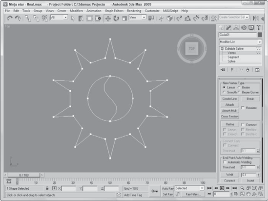
While holding down the Ctrl key, click on all the inner vertices of the star shape. Click the Chamfer button, and change the value until the chamfer looks like that in Figure 12.27, and press the Enter key.
Figure 12.27 shows the resulting ninja star.
To edit a segment, click the Segment subobject in the Modifier Stack or select the segment icon from the Selection rollout to enter segment subobject mode. Clicking again on either exits this mode. Segments are the lines or edges that run between two vertices. Many of the editing options work in the same way as when you're editing Vertex subobjects. You can select multiple segments by holding down the Ctrl key while clicking the segments, or you can hold down the Alt key to remove selected segments from the selection set. You can also copy segments when they're being transformed by holding down the Shift key. The cloned segments break away from the original spline, but are still a part of the Editable Spline object.
You can change segments from straight lines to curves by right-clicking the segment and selecting Line or Curve from the pop-up quadmenu. Line segments created with the Corner type vertex option cannot be changed to Curves, but lines created with Smooth and Bézier type vertex options can be switched back and forth.
Several Geometry rollout buttons work on more than one subobject type.
When you create a copy of a segment by moving a segment with the Shift key held down, you can enable the Connect Copy option to make segments that join the copied segment with its original. For example, if you have a single straight horizontal line segment, dragging it upward with the Copy Connect option enabled creates a copy that is joined to the original, resulting in a rectangle. Be aware that the vertices that connect to the original segment are not welded to the original segment.
When you select a segment, the Divide button becomes active. This button adds the number of vertices specified to the selected segment or segments. These new vertices are positioned based on the curvature of the segment with more vertices being added to the areas of greater curvature. Figure 12.28 shows the diamond shape (second row, second from right) after all four segments were selected, a value of 1 was entered into the spinner, and the Divide button was clicked.
The Detach button separates the selected subobjects from the rest of the object (opposite of the Attach button). When you click this button, the Detach dialog box opens, enabling you to name the new detached subobject. When segments are detached, you can select the Same Shape option to keep them part of the original object. The Reorient option realigns the new detached subobject to match the position and orientation of the current active grid. The Copy option creates a new copy of the detached subobject.
You can use Detach on either selected Spline or Segment subobjects.
Connect Copy is one of the features that you'll use and wonder how you ever got along without it. For this tutorial, you create a simple flower from a circle shape using the Connect Copy feature.
To create a simple flower using the Connect Copy feature, follow these steps:
Select Create
Right-click on the circle, and select Convert to
In the Modifier Stack, select the Segment subobject mode (keyboard shortcut, 2) and enable the Connect option in the Connect Copy section.
Select one of the circle segments, and with the Shift key held down, drag it outward away from the circle. Then repeat this step for each segment.
Figure 12.29 shows the results. With the Connect Copy option, you don't need to worry about the connecting lines.

For segment and spline subobjects, you can access a Surface Properties rollout that lets you assign a Material ID to the subobject. These Material IDs are used with the Multi/Sub-object Material available in the Material Editor. For example, suppose you've created a road from a bunch of splines that are part of the same object. You can assign one Material ID for the lines at the edge of the road that will be the curb and a different Material ID for the yellow lines running down the middle of the road. Separate materials then can be applied to each of the parts using the matching Material IDs.
Note
You can find information on Material IDs in Chapter 15, "Creating and Applying Standard Materials."
Using the Select ID button and drop-down list, you can locate and select all subobjects that have a certain Material ID. Simply select the Material ID that you are looking for and click the Select ID button, and all segments (or splines) with that Material ID are selected. Beneath the Select ID button is another drop-down list that lets you select segments by material name. The Clear Selection option clears all selections when the Select ID button is clicked. If disabled, then all new selections are added to the current selection set.
To edit a spline, click the Spline subobject in the Modifier Stack or select the spline icon from the Selection rollout. Transforming a spline object containing only one spline works the same way in subobject mode as it does in a normal transformation. Working in spline subobject mode lets you move splines relative to one another. Right-clicking a spline in subobject mode opens a pop-up quadmenu that lets you convert it between Curve and Line types. The Curve type option changes all vertices to Bézier type, and the Line type option makes all vertices Corner type. Spline subobject mode includes many of the buttons previously discussed as well as some new ones in the Geometry rollout.
The Reverse button is available only for Spline subobjects. It reverses the order of the vertex numbers. For example, a circle that is numbered clockwise from 1 to 4 is numbered counterclockwise after using the Reverse button. The vertex order is important for splines that are used for animation paths or loft compound objects.
The Outline button creates a spline that is identical to the one selected and offset by an amount specified by dragging or specified in the Offset value. The Center option creates an outline on either side of the selected spline, centered on the original spline. When the Center option is not selected, then an outline is created by offsetting a duplicate of the spline on only one side of the original spline. To exit Outline mode, click the Outline button again or right-click in the viewport. Figure 12.30 shows an arc that has had the Outline feature applied. In the right image, the Center option is enabled.

Boolean operations work with two or more splines that overlap one another. There are three different operations that can happen: You can combine the splines to create a single spline (union), you can subtract the overlapping area from one of the splines (subtract), or you can throw away everything except the overlapping area (intersection).
Note
You can also use Booleans to combine or subtract 3D volumes, which are covered in Chapter 26, "Working with Compound Objects."
The Boolean button works on overlapping closed splines and has three different options—Union, Subtraction, and Intersection—shown in Table 12.3. The splines must all be part of the same object. The Union option combines the areas of both splines, the Subtraction option removes the second spline's area from the first, and the Intersection option keeps only the areas that overlap.
To use the Boolean feature, select one of the splines and select one of the Boolean operation options. Then click the Boolean button, and select the second spline. Depending on which Boolean operation you chose, the overlapping area is deleted, the second spline acts to cut away the overlapping area on the first, or only the overlapping area remains. To exit Boolean mode, right-click in the viewport.
Note
Boolean operations can be performed only on closed splines that exist within a 2D plane.
Figure 12.31 shows the results of applying the Spline Boolean operators on a circle and star shape. The first image consists of the circle and star shapes without any Boolean operations applied. The second image shows the result of the Union feature, the third (circle selected first) and fourth (star selected first) use the Subtraction feature, and the fifth image uses the Intersection feature.
You can use the Mirror button to mirror a spline object horizontally, vertically, or along both axes. To use this feature, select a spline object to mirror and then locate the Mirror button. To the right of the Mirror button are three smaller buttons, each of which indicates a direction—Mirror Horizontally, Mirror Vertically, and Mirror Both—shown in Table 12.4. Select a direction, and then click the Mirror button. If the Copy option is selected, a new spline is created and mirrored. The About Pivot option causes the mirroring to be completed about the pivot point axes.
Figure 12.32 shows a little critter that has been mirrored horizontally, vertically, and both. The right image was horizontally mirrored with the About Pivot option disabled. Notice that the eye spline was mirrored about its own pivot.
The Trim button cuts off any extending portion between two overlapping splines. The splines must be part of the same object. To use the Trim feature, select the spline that you want to keep, click the Trim button, and then click the segment to trim. The spline you click is trimmed back to the nearest intersecting point of the selected object. This button works only in Spline subobject mode. The trimming command is dependent on the viewport that is active. When the Perspective or a Camera view is active, this command uses the Top viewport to trim.
Figure 12.33 shows a circle intersected by two ellipse shapes. The Trim button was used to cut the center sections of the ellipse shapes away.

The Extend button works in the reverse manner compared to the Trim button. The Extend button lengthens the end of a spline until it encounters an intersection. (There must be a spline segment to intersect.) To use the Extend command, click the Extend button and then click the segment to extend. The spline you click is extended. To exit Extend mode, right-click in the viewport or click the Extend button again.
The Infinite Bounds option works for both the Trim and Extend buttons. When enabled, it treats all open splines as if they were infinite for the purpose of locating an intersecting point. The Extend command, like Trim, is dependent on the active viewport.
The Close button completes an open spline and creates a closed spline by attaching a segment between the first and last vertices. You can check which vertex is first by enabling the Show Vertex Numbers in the Selection rollout. This is similar to the Connect feature (accessible in Vertex subobject mode), but the Connect feature can connect the end point of one spline to the end point of another as long as they are part of the same Editable Spline object. The Close feature works only in Spline subobject mode and connects only the end points of each given spline.
The Explode button performs the Detach command on all subobject splines at once. It separates each segment into a separate spline. You can select to explode all spline objects to separate Splines or Objects. If you select to explode to Objects, then a dialog box appears asking you for a name. Each spline uses the name you enter with a two-digit number appended to distinguish between the different splines.
Now that you're familiar with the many aspects of editing splines, you'll try to mimic one of the best spline producers in the world—the spider. The spider is an expert at connecting lines together to create an intricate pattern. (Luckily, unlike the spider that depends on its web for food, you won't go hungry if this example fails.)
To create a spider web from splines, follow these steps:
Select Create
Select the Spline subobject in the Modifier Stack (or press the 3 key) to enter Spline subobject mode.
Click the Create Line button in the Geometry rollout, and click in the center of the circle and again outside the circle to create a line. Then right-click to end the line. Repeat this step until 12 or so radial lines extend from the center of the circle outward.
Select and right-click on the 2D Snaps Toggle in the main toolbar. In the Grid and Snap Settings dialog box, enable the Vertex and Edge/Segment options and close the dialog box. While you're still in Create Line mode, click on the circle's center and create lines in a spiral pattern by clicking on each radial line that you intersect. Right-click to end the line when you finally reach the edge of the circle. Then right-click again to exit Create Line mode.
Select the circle shape, and click the Trim button. Then click on each line segment on the portion that extends beyond the circle. This trims the radial lines to the edge of the circle. Click the Trim button again when you are finished to exit Trim mode.
Change to Vertex subobject mode by clicking Vertex in the Modifier Stack (or by pressing 1). Turn off the Snap toggle and then select all the vertices in the center of the circle, and click the Fuse button.
Figure 12.34 shows the finished spider web. (I have a new respect for spiders.)

In the Modifiers menu is a whole submenu of modifiers that apply strictly to splines. You can find these modifiers in the Modifiers
Of the modifiers that work only on splines, several of these duplicate functionality that is available for Editable Splines, such as the Fillet/Chamfer modifier. Applying these features as modifiers gives you better control over the results because you can remove them using the Modifier Stack at any time.
This modifier enables you to select spline subobjects, including Vertex, Segment, and Spline. You can copy and paste named selection sets. The selection can then be passed up the Stack to the next modifier. The Spline Select modifier provides a way to apply a modifier to a subobject selection.
The Modifiers
You can also Copy and Paste selection sets using the Copy and Paste buttons.
You can use the Delete Spline modifier to delete spline subobjects. This is helpful if you want to remove a spline from an object so it doesn't render without destroying the curvature of the other splines in the object. To do this, simply select the splines to remove from the object in Spline subobject mode and then apply the Delete Spline modifier. The selection will be passed up the stack.
The Normalize Spline modifier adds new points to the spline. These points are spaced regularly based on the Segment Length value. Figure 12.35 shows a simple flower shape with the Spline Select modifier applied so you can see the vertices. The Normalize Spline modifier was then applied with Segment Length values of 1, 5, 10, and 15. Notice that the shape is changing with fewer vertices.
You can use the Fillet/Chamfer modifier to Fillet or Chamfer the corners of shapes. Fillet creates smooth corners, and Chamfer adds another segment where two edges meet. Parameters include the Fillet Radius and the Chamfer Distance. Both include an Apply button. The results of this modifier are the same as if you were to use the Fillet or Chamfer features of an Editable Spline.

The Renderable Spline modifier lets you make any selected spline renderable. The Parameters rollout includes the same controls that are available for Editable Splines including Thickness, Sides, and Angle values.
The Sweep modifier works just like the loft compound object, letting you follow a spline path with a defined cross section, except that the Sweep modifier is a modifier, making it easier to apply and remove from splines and shapes. Another benefit of the Sweep modifier is that it has several Built-In Sections available that you can choose or you can pick your own. The built-in sections include many that are useful for architectural structures including Angle, Bar, Channel, Cylinder, Half Round, Pipe, Quarter Round, Tee, Tube, and Wide Flange.
Using the Merge From File button, you can choose a shape from another file. You can also set the number of interpolation steps. The Sweep Parameters rollout includes options for mirroring, offsetting, smoothing, aligning, and banking the generated sweep. The Union Intersecting option causes self-intersecting portions of the path to be combined using a union Boolean command. You also can select to have mapping coordinates generated on the sweep object.
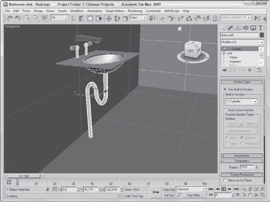
If you want to create a shape that renders in the scene, you can use the Renderable Spline option or you can apply the Sweep modifier. In this example, you apply the Sweep modifier to a line that defines the path of a bathroom sink drain.
To create a pipe that follows a spline, follow these steps:
Open the Bathroom sink.max file from the Chap 12 directory on the DVD.
This file includes a simple bathroom sink and a line that defines its drain path.
With the spline selected, choose the Modifiers
In the Section Type rollout, choose the Cylinder option from the Built-In Section drop-down list. Then set the Radius value to 10.
Figure 12.36 shows the resulting sink complete with a drain created using a cylinder cross section.
The Trim/Extend modifier lets you trim the extending end of a spline or extend a spline until it meets another spline at a vertex. The Pick Locations button turns on Pick mode, where the cursor changes when it is over a valid point. Operations include Auto, Trim Only, and Extend Only with an option to compute Infinite Boundaries. You can also set the Intersection Projection to View, Construction Plane, or None.
The Shape Check utility is helpful in verifying that a shape doesn't intersect itself. Shapes that have this problem cannot be extruded, lofted, or lathed without problems. To use this utility, open the Utilities panel (the icon for the Utilities panel looks like a hammer) and click the More button. Select Shape Check from the Utilities dialog box list, and click OK.
Note
The Shape Check utility is found in the Utilities panel and not in the Modifiers menu.
The Shape Check rollout includes only two buttons: Pick Object and Close. Click the Pick Object button, and click the shape you want to check. Any intersection points are displayed as red squares, as shown in Figure 12.37, and the response field displays "Shape Self-Intersects." If the shape doesn't have any intersections, then the response field reports "Shape OK."

Although splines can be rendered, the real benefit of splines in Max is to use them to create 3D objects and for animation paths. You can use splines in several ways as you model 3D objects, including Loft objects and modifiers. One way to use splines to make 3D objects is with modifiers.
Note
As you build splines that will be used to create mesh objects, remember that the number of vertices in a spline determines the number of segments in the final mesh. For example, if you have a spline with 10 points that is extruded 5 times, then you'll end up with more than 50 polygons, but the same spline with 80 points would have more than 400 polygons.
Note
Using splines to create an animation path is covered in Chapter 20, "Understanding Animation and Keyframe Basics," and Loft objects are covered in Chapter 26, "Working with Compound Objects." General information on working with modifiers is covered in Chapter 11, "Introducing Modifiers and Using the Modifier Stack."
Because splines are drawn in a 2D plane, they already include two of the three dimensions. By adding a Height value to the shape, you can create a simple 3D object. The process of adding Height to a shape is called extruding.
To extrude a shape, you need to apply the Extrude modifier. To do so, select a spline object and choose Modifiers

In Woodshop 101, you use a router to add a designer edge to doorframes, window frames, and shelving of all sorts. In Woodshop 3D, the Boolean tools work nicely as you customize a bookshelf.
To create a custom bookshelf using spline Boolean operations, follow these steps:
Open the Bookshelf.max file from the Chap 12 directory on the DVD.
This file includes a triangle shape drawn with the Line primitive that is overlapped by three circles. All these shapes have been converted and combined into a single Editable Spline object.
Select the shape, open the Modify panel, and select the Spline subobject mode (or press the 3 key) and select the triangle shape.
Select the Subtraction Boolean operation (the middle icon) in the Geometry rollout, and click the Boolean button. Then select each of the circles and right-click to exit Boolean mode. Then click Spline in the Modifier Stack again to exit subobject mode.
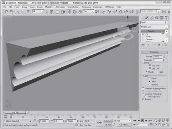
Back in the Modify panel, select the Extrude modifier from the Modifier drop-down list and enter an Amount of 1000. Select Zoom Extents All to resize your viewports, switch to the Perspective viewport and view your bookshelf.
Figure 12.39 shows the finished bookshelf in the Perspective viewport ready to hang on the wall.
Another useful modifier for 2D splines is the Lathe. This modifier rotates the spline about an axis to create an object with a circular cross section (such as a baseball bat). In the Parameters rollout, you can specify the Degrees to rotate (a value of 360 makes a full rotation) and Cappings, which add ends to the resulting mesh. Additional options include Weld Core, which causes all vertices at the center of the lathe to be welded together, and Flip Normals, which realigns all the normals.
The Direction option determines the axis about which the rotation takes place. The rotation takes place about the object's pivot point.
Warning
If your shape is created in the Top view, then lathing about the screen Z-axis produces a thin disc without any depth.
As an example of the Lathe modifier, you create a simple crucible, although you could produce any object that has a circular cross section. A crucible is a thick porcelain cup used to melt chemicals. I chose this as an example because it is simple (and saying "crucible" sounds much more scientific than "cup").
To create a crucible using the Lathe modifier, follow these steps:
Open the Crucible.max file from the Chap 12 directory on the DVD.
This file includes a rough profile cross-section line of the crucible that has been converted to an Editable Spline.
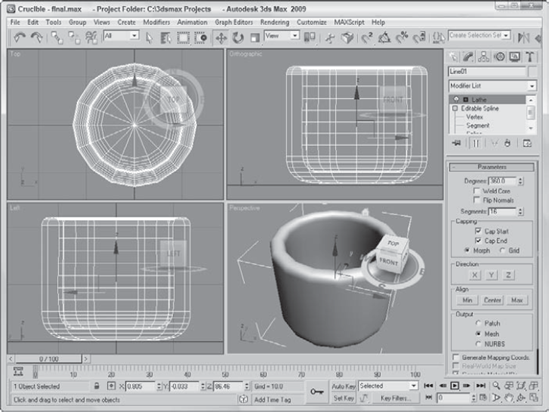
Select the line, and select the Modifiers
Figure 12.40 shows the finished product. You can easily make this into a coffee mug by adding a handle. To make a handle, simply loft an ellipse along a curved path.
Another common set of modifiers that can be used with splines and shapes are the Bevel and Bevel Profile modifiers.
Note
Both the Bevel and Bevel Profile modifiers are not found in the Modifiers menu. To apply them, use the Modifier List found in the Modifier Stack. They are among the Object-Space modifiers.
Using the Bevel modifier, you can extrude and outline (scale) the shape in one operation. With the Bevel modifier, you can set the Height and Outline values for up to three different bevel levels. The Capping options let you select to cap either end of the beveled shape. The Cap Type can be either Morph or Grid. The Morph type is for objects that will be morphed. You can specify that the Surface use Linear or Curved Sides with a given number of segments. You can also select to Smooth Across Levels automatically. The Keep Lines from Crossing option avoids problems that may result from crossing lines.
The Bevel Profile modifier lets you select a spline to use for the bevel profile.
You can create a simple ring using a Tube or Torus primitive object (or with an extruded donut shape), but if you want the ring to have a unique profile, then the Bevel and Bevel Profile modifiers are what you need.
To create a couple of unique rings with the Bevel and Bevel Profile modifiers, follow these steps:
Select Create
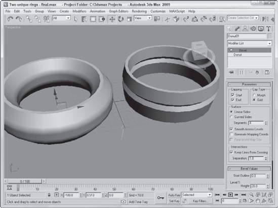
Select the ring on the left in the Top viewport, open the Modify panel, and select the Bevel modifier from the Modifier List drop-down list in the Modifier Stack. In the Bevel Values rollout, set the Start Outline to 0, the Height values for Levels 1, 2, and 3 to 20, the Outline for Level 1 to 15, and the Outline value for Level 3 to −15. Then enable the Smooth Across Levels option.
Select Create
Select the donut shape on the right, open the Modify panel, and choose the Bevel Profile modifier from the Modifier List in the Modifier Stack. In the Parameters rollout, click the Pick Profile button and select the profile curve.
Figure 12.41 shows the finished rings.
The CrossSection modifier is one of two modifiers that collectively are referred to as the surface tools. The surface tools provide a way to cover a series of connected cross sections with a surface. The CrossSection modifier connects the vertices of several cross-sectional splines together with additional splines in preparation for the Surface modifier. These cross-sectional splines can have different numbers of vertices. Parameters include different spline types such as Linear, Smooth, Bézier, and Bézier Corner.
Note
The second half of the surface tools is the Surface modifier. You can find this modifier and an example in Chapter 27, "Modeling with Patches and NURBS." The surface tools are similar in many ways to the Loft compound object, which is covered in Chapter 26, "Working with Compound Objects."
As this chapter has shown, there is much more to splines than just points, lines, and control handles. Splines in Max are one of the fundamental building blocks and the pathway to advanced modeling skills using NURBS.
This chapter covered the following spline topics:
Understanding the various shape primitives
Editing splines
Working with the various spline subobjects
Applying modifiers to splines
The next chapter continues your voyage down the modeling pathway with perhaps the most common modeling types—meshes and polys.