
Although Max consists of many different interface elements, such as panels, dialog boxes, and menus, the viewports are the main areas that will catch your attention. The four main viewports make up the bulk of the interface. You can think of the viewports as looking at the television screen instead of the remote. Learning to control and use the viewports can make a huge difference in your comfort level with Max. Nothing is more frustrating than not being able to rotate, pan, and zoom the view.
The viewports have numerous settings that you can use to provide thousands of different ways to look at your scene, and beginners can feel frustrated at not being able to control what they see. Max includes several handy little gizmos that make navigating the viewports much easier. This chapter includes all the details you need to make the viewports reveal their secrets.
It seems silly to be talking about 3D space because we live and move in 3D space. If we stop and think about it, 3D space is natural to us. For example, consider trying to locate your kids at the swimming pool. If you're standing poolside, the kids could be to your left or right, in front of you or behind you, or in the water below you or on the high dive above you. Each of these sets of directions represents a dimension in 3D space.
Now imagine that you're drawing a map that pinpoints the kid's location at the swimming pool. Using the drawing (which is 2D), you can describe the kid's position on the map as left, right, top, or bottom, but the descriptions of above and below have been lost. By moving from a 3D reference to a 2D one, the number of dimensions has decreased.
The conundrum that 3D computer artists face is how do you represent 3D objects on a 2D device such as a computer screen? The answer that 3ds Max provides is to present several views, called viewports, of the scene. A viewport is a small window that displays the scene from one perspective. These viewports are the windows into Max's 3D world. Each viewport has numerous settings and viewing options.
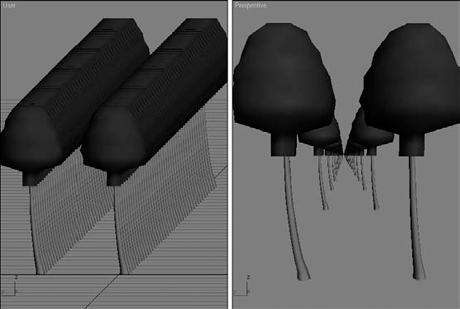
When it comes to views in the 3D world, two different types exist—Axonometric and Perspective. Axonometric views are common in the CAD world where the viewer is set at an infinite distance from the object such that all parallel lines remain parallel. A Perspective view simulates how our eyes actually work and converges all points to a single location off in the distance.
You can see the difference between these two types of views clearly if you look at a long line of objects. For example, if you were to look down a long row of trees lining a road, the trees would eventually merge on the horizon. In Axonometric views, lines stay parallel as they recede into the distance. Figure 2.1 shows this example with the Axonometric view on the left and the Perspective view on the right.
If you dig a little deeper into Axonometric views, you find two different types—Orthographic and Isometric. Orthographic views are displayed from the perspective of looking straight down an axis at an object. This reveals a view in only one plane. Because orthographic viewports are constrained to one plane, they show the actual height and width of the object, which is why the CAD world uses orthographic views extensively. Isometric views are not constrained to a single axis and can view the scene from any location, but all dimensions are still maintained.
Available orthographic viewports in Max include Front, Back, Top, Bottom, Left, and Right. Max starts up with the Top, Front, and Left orthographic viewports visible. The top-left corner of the viewport displays the viewport name. The fourth default viewport is a Perspective view.
Figure 2.2 shows the viewports with Viewpoint model of a PT-328 U.S. Torpedo boat. You can see the model from a different direction in each viewport. If you want to measure the boat's length from aft to stern, you could get an accurate measurement using the Top or Left viewport, whereas you can use the Front and Left viewports to measure its precise height. So, using these different viewports, you can accurately work with all object dimensions.

Isometric views in Max are called User viewports. You can create a User viewport by rotating any of the Orthographic views.
Tip
Max includes several keyboard shortcuts for quickly changing the view in the active viewport including T (Top view), B (Bottom view), F (Front view), L (Left view), C (Camera view), $ (Spotlight view), P (Perspective view), and U (Isometric User view). Pressing the V key opens a quadmenu that lets you select a new view.
One of the key advantages of working in 3D is that you can view your models from an endless number of viewpoints, but you won't be able to switch to these endless viewpoints until you learn to navigate them. Being able to quickly navigate the viewports is essential to working in Max and one of the first skills you should master.
To make the process of navigating within the viewports and switching among the various views easier, Max has some navigation gizmos that make this chore easy. These semi-transparent gizmos hover above the viewport and provide a way to change the view without having to access a tool, select a menu, or even use a keyboard shortcut.
The ViewCube is positioned by default in the upper-right corner of each viewport. It consists of a 3D cube that is labeled on each side and centered in a ring located on the ground plane. Its purpose is to show the current orientation of the viewport, but it is also interactive and provides a way to quickly move among the different views.
If you drag the cursor over the top of the ViewCube, you'll notice that the cube's faces, corners, and edges are highlighted as the cursor moves over them. If you click when any of the cube's parts are highlighted, the viewport is animated and moves to the new view so it's positioned as if it's pointing at the selected part. By slowly animating the transition to the new view, you get a better idea of the size and shape of the model. It also makes it easy to reorient the model if it gets twisted around to an odd angle. For example, if you click on the cube's face labeled Top, then the view moves from its current view until the Top view is assumed.
The ViewCube also lets you click and drag on the cube to rotate the view around. You can also click and drag on the base ring to spin the model about its current orientation. Above the ViewCube is a small house icon. Clicking this icon changes the view to the defined home view. You can set the Home view by right-clicking on the ViewCube and selecting the Set Current View as Home option from the pop-up menu. These same menu options are also available in the Views
Other pop-up menu options let you switch the view between Orthographic and Perspective views. You can also set the current view as Front, reset the Front view, and open the ViewCube panel that is located in the Viewport Configuration dialog box, as shown in Figure 2.3.
The ViewCube panel in the Viewport Configuration dialog box includes settings for turning the ViewCube on and off for All Views or for Only the Active View. You can also set the ViewCube size and its inactive opacity.
Tip
If you like the ViewCube, but you feel that it takes up too much of the viewport, then you can change its size to Small or Tiny or you can set its inactive opacity to 0. When its inactive opacity is set to 0, then the ViewCube isn't visible at all until you move the cursor over it causing it to appear.
There are also options to control what happens when you click or drag the ViewCube. There is an option to snap to the closest view when dragging the ViewCube and options to automatically make the models fit to the view when the view changes, to use animated transitions, and to keep the scene upright. If you find that the view keeps ending up at odd angles when you drag the ViewCube, then try enabling the Keep Scene Upright option. Finally, there is an option to display the compass under the ViewCube and a setting for the Angle of North so you can change the compass' orientation. The compass is helpful in being able to spin the model around.
The ViewCube is great for switching between the default views and for rotating the current view, but there are many additional navigation tools that aren't covered with the ViewCube. To handle many of these other navigation tools, such as zooming and panning, Max includes the SteeringWheels, another gizmo for navigating the viewports.
When Max is first started, the SteeringWheels are locked to the lower-left corner of the viewport and an introduction dialog box appears, as shown in Figure 2.4, when you move the mouse cursor over the Steering Wheel. This introduction dialog box lets you choose from six different wheel choices. These wheel choices come in two sizes, large and mini, with three different purposes: full navigation, viewing objects, and touring buildings.

Figure 2.3. The ViewCube panel in the Viewport Configuration dialog box lets you control where and how the ViewCube appears.
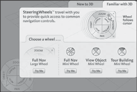
After you select a wheel by clicking the Try Me button, the introduction dialog box disappears and the steering wheel moves with the mouse cursor. Also the different parts of the wheel are highlighted when you move over them. The View Object Wheel and the Tour Building Wheel are both subsets of the Full Navigation Wheel. The full navigation wheel includes the following modes:
Zoom: Causes the view to zoom in and out of the scene about the pivot. The pivot is set by holding down the Ctrl key while clicking.
Orbit: Causes the view to orbit about the pivot. The pivot is set by holding down the Ctrl key while clicking.
Pan: Causes the view to pan in the direction that you drag the cursor.
Rewind: As you change the scene, Max remembers each view where you stop and keeps these views in a buffer. The Rewind mode displays these views as small thumbnails, as shown in Figure 2.5, and lets you move through them by dragging the mouse. This allows you to rewind back and move forward through the buffered views.
Center: Lets you click on an object to be the pivot center for zooming and orbiting.
Walk: Moves you forward through the scene as if you were walking through it. Holding down the Shift key lets you move up and down.
Look: Causes the camera to rotate side to side as if looking to the side.
Up/Down: Moves the view up and down from the current location.

In the upper-right corner of the wheel is a small X icon. This icon is used to close the steering wheel gizmo. In the lower-right corner of the wheel is a small down arrow. This icon opens a pop-up menu. Using the pop-up menu, you can select a different wheel type, go the home view as defined by the ViewCube, increase or decrease the walk speed, restore the original center, or open the SteeringWheels panel in the Viewport Configuration dialog box, as shown in Figure 2.6. These same options are also available in the Views
Warning
In the early releases of Max, the keyboard shortcut for the SteeringWheels gizmo wasn't working.
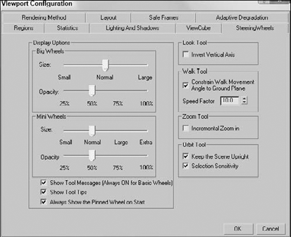
Figure 2.6. The SteeringWheels panel in the Viewport Configuration dialog box includes settings for the various wheels.
Using the SteeringWheels panel in the Viewport Configuration dialog box, you can set the size and opacity of the SteeringWheels. There are also settings for controlling many of the different modes.
Over time, navigating the viewports becomes second nature to you, but you need to practice to get to that point. In this tutorial, you get a chance to take the viewports for a spin—literally.
To practice navigating a viewport, follow these steps:
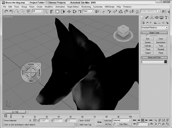
Open the Bruce the dog.max file from the Chap 02 directory on the DVD.
This file includes a model of a dog (affectionately named Bruce) created by Viewpoint. It provides a reference as you navigate the viewport. The active viewport is the Perspective viewport.
Click the Min/Max Toggle button (or press Alt+W) to make the Perspective viewport fill the space of all four viewports.
Click on the Front face in the ViewCube to transition the view to the front view. Then move the cursor over the upper-right corner of the ViewCube and click to set the view to a perspective view.
Select the Views

With the Steering Wheel still active, move the cursor over the Pan button and drag the window until Bruce's head is centered evenly in the viewport, as shown in Figure 2.7. Right-click in the viewport to exit the selected navigation tool.
Select the Rewind option in the Steering Wheel and drag the mouse to rewind the view back to its front position, as shown in Figure 2.8.

Now that I've explained the viewport navigation gizmos, I'll explain another easy way to control the viewports. Often, the quickest way to control the viewports is with the mouse. To really get the benefit of the mouse, you need to use a mouse with a scroll wheel (which also acts as a middle mouse button).
Rolling the scroll wheel in the active viewport zooms in to and out of the viewport by steps just like the bracket keys ([ and ]). You can zoom precisely by holding down the Ctrl and Alt keys while dragging the scroll wheel.
Clicking and dragging the scroll wheel button pans the active viewport. Clicking and dragging with the Alt button held down rotates the active viewport. If the scroll wheel isn't working, check the Viewports panel in the Preference Settings dialog box. You can select to use the scroll wheel control to pan and zoom in the viewports or to define and use Strokes.
Warning
Be careful when zooming in with the scroll wheel. If you zoom in too far, the internal field of width approaches its minimum value and zooming becomes unstable. If this happens, you can select the Views
Note
Strokes are covered in Chapter 4, "Customizing the Max Interface and Setting Preferences."
Although the ViewCube, the SteeringWheels and the scroll wheel make navigating the viewports easy, you can still use the standard navigation tools located in the bottom-right corner of the interface. The standard viewports show you several different views of your current project, but within each viewport you can zoom in on certain objects, pan the view, or rotate about the center of the viewport. To zoom, pan, and rotate the default views, you can use the Viewport Navigation Control buttons. In Table 2.1, the keyboard shortcut for each button is listed in parentheses next to its name.
Tip
The active viewport is always marked with a yellow border.
Table 2.1. Viewport Navigation Controls
Toolbar Button | Name | Description |
|---|---|---|
Zoom (Alt+Z or [ or ]) | Moves closer to or farther from the objects in the active viewport by dragging the mouse or zooming by steps with the bracket keys. | |
Zoom All | Zooms in to or out of all the viewports simultaneously by dragging the mouse. | |
Zoom Extents (Ctrl+Alt+Z), Zoom Extents Selected | Zooms in on all objects or just the selected object until it fills the active viewport. | |
Zoom Extents All (Ctrl+Shift+Z), Zoom Extents All Selected (Z) | Zooms in on all objects or just the selected object until it fills all the viewports. | |
Field of View Region Zoom (Ctrl+W) | The Field of View button (available only in the Perspective view) controls the width of the view. The Region Zoom button zooms in to the region selected by dragging the mouse. | |
Pan (Ctrl+P or I), Walk Through | Moves the view to the left, to the right, up, or down by dragging the mouse or by moving the mouse while holding down the I key. The Walk Through feature moves through the scene using the arrow keys or a mouse like a first-person video game. | |
Arc Rotate (Ctrl+R), Arc Rotate Selected, Arc Rotate SubObject | Rotates the view around the global axis, selected object, or subobject by dragging the mouse. | |
Min/Max Toggle (Alt+W) | Makes the active viewport fill the screen, replacing the four separate viewports. Clicking this button a second time shows all four viewports again. |
Warning
When one of the Viewport Navigation buttons is selected, it is highlighted yellow. You cannot select, create, or transform objects while one of these buttons is highlighted. Right-clicking in the active viewpoint reverts to select object mode.
You can zoom in to and out of the scene in several ways. Clicking the Zoom (Alt+Z) button enters zoom mode where you can zoom in to and out of a viewport by dragging the mouse. This works in whichever viewport you drag in. To the right of the Zoom button is the Zoom All button, which does the same thing as the Zoom button, only to all four viewports at once. If you hold down the Ctrl key while dragging in Zoom mode, the zoom action happens more quickly, requiring only a small mouse movement to get a large zoom amount. Holding down the Alt key while dragging in Zoom mode has the opposite effect—the zoom happens much more slowly and a large mouse move is required for a small zoom amount. This is helpful for fine-tuning the zoom.
The Zoom Extents (Ctrl+Alt+Z) button zooms the active viewport so that all objects (or the selected objects with the Zoom Extents Selected button) are visible in the viewport. A Zoom Extents All (Ctrl+Shift+Z) button is available for zooming in all viewports to all objects' extents; the most popular zoom command is Zoom Extents All Selected (Z), which is for zooming in to the extents of the selected objects in all viewports.
You can use the brackets keys to zoom in ([) and out (]) by steps. Each key press zooms in (or out) another step. The Region Zoom (Ctrl+W) button lets you drag over the region that you want to zoom in on. If you select a non-orthogonal view, such as the Perspective view, the Region Zoom button has a flyout called the Field of View. Using this button, you can control how wide or narrow the view is. This is like using a wide angle or telephoto lens on your camera. This feature is different from zoom in that the perspective is distorted as the Field of View is increased.
Note
Field of View is covered in more detail in Chapter 18, "Configuring and Aiming Cameras."
The Viewport Navigation Controls also offer two ways to pan in a viewport. In Pan mode (Ctrl+P), dragging in a viewport pans the view. Note that this doesn't move the objects, only the view. The second way to pan is to hold down the I key while moving the mouse. This is known as an interactive pan. In addition, the Ctrl and Alt keys can be held down to speed or slow the panning motions.
The Walk Through button, found as a flyout button under the Pan button, allows you to move through the scene in the Perspective or Camera viewport using the arrow keys or the mouse just as you would if you were playing a first-person computer game. When this button is active, the cursor changes to a small circle with an arrow inside it that points in the direction you are moving.
Warning
The Pan button is a flyout only if the Perspective view or a Camera view is selected.
The Walk Through feature includes several keystrokes for controlling the camera's movement. The arrow keys move the camera forward, left, back, and right (or you can use the W, A, S, and D keys). You can change the speed of the motion with the Q (accelerate) and Z (decelerate) keys or with the [ (decrease step size) and ] (increase step size) keys. The E and C keys (or the Shift+up or Shift+down arrows) are used to move up and down in the scene. The Shift+spacebar key causes the camera to be set level. Dragging the mouse while the camera is moving changes the direction in which the camera points.
A handy alternative to Walk Through mode is the Walkthrough Assistant, which is found on the Animation menu. This utility opens a dialog box that includes buttons for creating and adding a camera to a path. It also has controls from turning the view side to side as the camera moves along the path.
Note
The Walkthrough Assistant is new to 3ds Max 2009.
Note
The Walkthrough Assistant is covered in more detail in Chapter 21, "Animating with Constraints and Controllers."
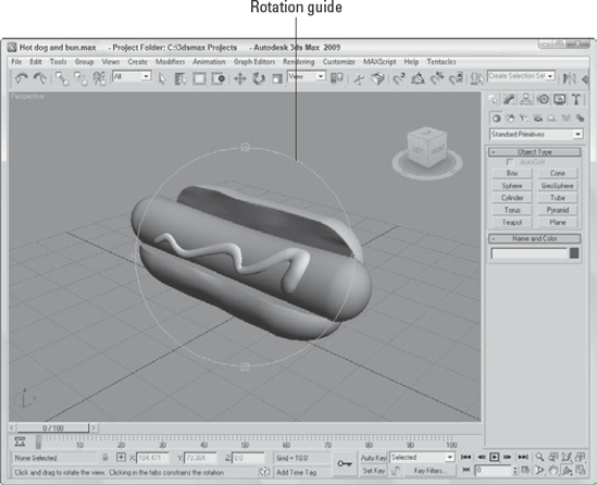
Rotating the view can be the most revealing of all the view changes. When the Arc Rotate (Ctrl+R) button is selected, a rotation guide appears in the active viewport, as shown in Figure 2.9. This rotation guide is a circle with a square located at each quadrant. Clicking and dragging the left or right squares rotates the view side to side; the same action with the top and bottom squares rotates the view up and down. Clicking within the circle and dragging rotates within a single plane, and clicking and dragging outside of the circle rotates the view about the circle's center either clockwise or counterclockwise. If you get confused, look at the cursor, which changes depending on the type of rotation. The Ctrl and Alt keys also can speed and slow the rotating view. Figure 2.9 also shows a viewport that has been maximized using the Min/Max Toggle button.
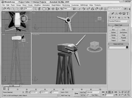
Sooner or later, the viewports will feel too small. When this happens, you have several ways to increase the size of your viewports. The first trick to try is to change the viewport sizes by clicking and dragging any of the viewport borders. Dragging on the intersection of the viewports resizes all the viewports. Figure 2.10 shows the viewports after being dynamically resized.
Tip
You can return to the original layout by right-clicking on any of the viewport borders and selecting Reset Layout from the pop-up menu.
The second trick is to use the Min/Max Toggle (Alt+W) to expand the active viewport to fill the space reserved for all four viewports. Clicking the Min/Max Toggle (or pressing Alt+W) a second time returns to the defined layout.
Maximizing the viewport helps temporarily, but you can take another step before convincing your boss that you need a larger monitor. You can enter Expert Mode by choosing Views
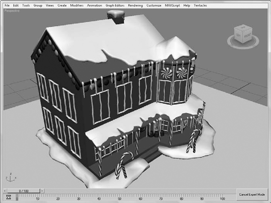
With most of the interface elements gone, you'll need to rely on the menus, keyboard shortcuts, and quadmenus to execute commands. To re-enable the default interface, click the Cancel Expert Mode button in the lower right of the Max window (or press Ctrl+X again). Figure 2.11 shows the interface in Expert Mode.
You can set any viewport to be a Camera view (C) or a Spotlight view ($) if a camera or a spotlight exists in the scene. When either of these views is active, the Viewport Navigation Control buttons change. In Camera view, controls for dolly, roll, truck, pan, orbit, and field of view become active. A light view includes controls for falloff and hotspots.
Note
Chapter 18, "Configuring and Aiming Cameras," and Chapter 19, "Using Lights and Basic Lighting Techniques," cover these changes in more detail.
Although the Viewport Navigation Controls are focused on controlling what is visible in the viewports, there are also a number of useful commands in the Views menu that directly affect the viewports.
If you get lost in your view, you can undo and redo viewport changes with Views
You can save changes made to a viewport by using the Views
Note
The Save and Restore Active Viewport commands do not save any viewport configuration settings, just the navigated view. Saving an active view uses a buffer, so it remembers only one view for each viewport.
If your scene gets too complicated, you can experience some slow-down waiting for each viewport to be updated with changes, but fear not, because several options will come to your rescue. The first option to try is to disable a viewport.
You can disable a viewport by right-clicking on the viewport's name and selecting the Disable View menu command from the pop-up menu, or you can press the keyboard shortcut, D. When a disabled viewport is active, it is updated as normal; when it is inactive, the viewport is not updated at all until it becomes active again. Disabled viewports are identified by the word "Disabled," which appears next to the viewport's name in the upper-left corner.
Another trick to increase the viewport update speed is to disable the Views
Sometimes when changes are made, the viewports aren't completely refreshed. This typically happens when dialog boxes from other programs are moved in front of the viewports. If this happens, you can force Max to refresh all the viewports with the Views
The Views menu also includes several commands for making scene details such as materials, lighting and shadows visible in the viewports. Each of these options can slow down the refresh rate, but they provide immediate feedback, which is often helpful.
Texture maps can also take up a lot of memory. The Views
Note
More on applying texture maps is covered in Chapter 17, "Adding Material Details with Maps."
Options for enabling lighting and shadow effects within the viewports are located in the Views
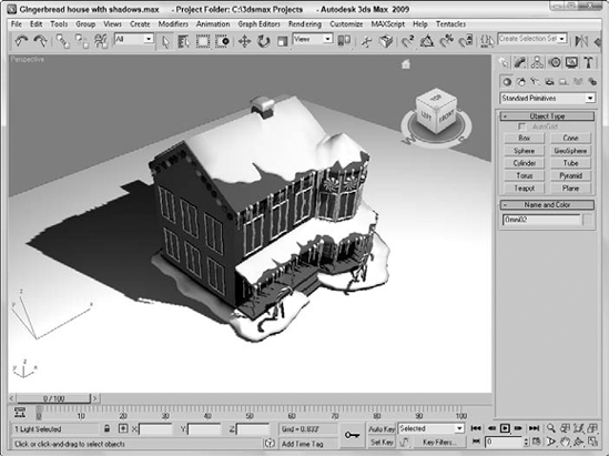
The options available in the Viewport Shading submenu are Off, which shows no shadows and limits the lights to 8; Good, which allows interactive lights and fast shadowing; and Best, which allows high-quality per pixel shadowing, as shown in Figure 2.12, with up to 64 concurrent lights.
Previewing shadows in the viewport requires the Direct3D driver to be used and your video card must support Shader Model 2.0 (for the Good display option) or Shader Model 3.0 (for the Best display option). You can check to see which viewport shading method you can use by selecting the Help
Note
If your computer doesn't support either of these Shader models, then the options will be disabled in the Views menu, the quadmenu, and the Viewport Configuration dialog box.
Another option, Auto Display Selected Lights, is helpful when you're working on placing and aiming lights in the scene. It causes the selected light to automatically be displayed in the shaded viewport.
For the Shadows options, you can use the Enable Viewport Shadows Selected, which is a good idea if you're placing objects because it only enables viewport shadows for the selected light. It allows you to see if objects are positioned where the shadows are cast on them. The Views menu also includes options for locking lights and for selecting those lights that are enabled or that are displaying shadows.
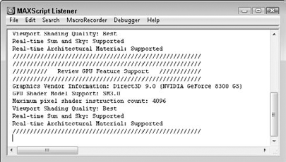
Figure 2.13. The Help
The Viewport Configuration dialog box includes a number of settings for the viewport lighting and shadows in the Lighting and Shadows panel, shown in Figure 2.14. This panel sets the default Viewport Shading method, which is used to show lights and shadows interactively in the viewport. You also can override the Shadow Intensity to dim the shadows if they are too dark.
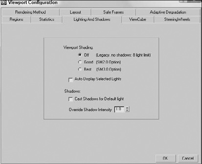
Figure 2.14. The Lighting and Shadows panel includes default settings for displaying interactive lights and shadows in the viewport.
To enable lighting and shadows in the viewports, follow these steps:
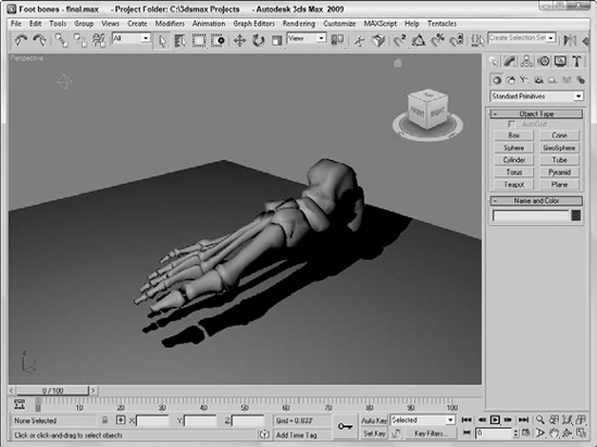
Open the Foot bones.max file from the Chap 02 directory on the DVD.
This file includes a set of foot bones created by Viewpoint Datalabs. There is also an Omni light added to the scene.
Right-click in the viewport and select Viewport Lighting and Shadows
If shadows are enabled for the light, then you'll see them in the viewport. If you don't see any shadows, then select the light object and choose the Viewport Lighting and Shadows
Click on the Select and Move toolbar button and drag the light object about the scene.
The shadows under the foot bones are automatically updated as the light is moved, as shown in Figure 2.15.
The Adaptive Degradation Toggle (O) is an option that enables the viewport display to degrade the image resolution (by downgrading the rendering method) in order to maintain a consistent frame rate. This can help when you're trying to navigate a complex scene that is taking a while to redraw.
If the Viewport Navigation Controls help define what you see, then the Viewport Configuration dialog box helps define how you see objects in the viewports. You can configure each viewport using this dialog box. To open this dialog box, choose the Views
The Viewport Configuration dialog box contains several panels, including Rendering Method, Layout, Safe Frames, Adaptive Degradation, Regions, Statistics, Lighting and Shadows, ViewCube, and SteeringWheels. The Preference Settings dialog box also includes many settings for controlling the behavior and look of the viewports.
Note
See Chapter 4, "Customizing the Max Interface and Setting Preferences," for more on the Preference Settings dialog box and all its options.
Complex scenes take longer to display and render. The renderer used for the viewports is highly optimized to be very quick, but if you're working on a huge model with lots of complex textures and every viewport is set to display the highest quality view, then updating each viewport can slow the program to a crawl. The Viewport Configuration dialog box's Rendering Method panel, shown in Figure 2.16, lets you set the rendering settings for the Active Viewport, All Viewports, or All but Active viewport.
Tip
If you ever get stuck waiting for Max to complete a task, such as redrawing the viewports, you can always press the Escape key to suspend any task immediately and return control to the interface.
Note
These settings have no effect on the final rendering specified using the Rendering menu. They affect only the display in the viewport.
The Rendering Level options, from slowest to fastest, include the following:
Smooth+Highlights: Shows smooth surfaces with lighting highlights
Smooth: Shows smooth surfaces without any lighting effects
Facets+Highlights: Shows individual polygon faces and lighting highlights
Facets: Shows individual polygon faces without any lighting effects
Flat: Shows the entire object using a single color
Hidden Line: Shows only polygon edges facing the camera
Lit Wireframes: Shows all polygon edges with lighting effects
Wireframe: Shows all polygon edges only
Bounding Box: Shows a box that would enclose the object
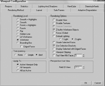
Figure 2.16. The Rendering Method panel holds controls for specifying the Rendering Level and several other viewport rendering options.
Although it really isn't a rendering method, the Edged Faces option shows the edges for each face when a shaded rendering method is selected. You can enable and disable this option with the F4 keyboard shortcut. Figure 2.17 shows, side by side, all the various viewport rendering methods applied to a simple sphere.

Figure 2.17. The viewport rendering methods are shown from left to right. First Row: Smooth+Highlights, Smooth, Facets+Highlights, Facets, and Flat. Second Row: Hidden Line, Lit Wireframes, Wireframe, Bounding Box, and Edged Faces applied to Smooth+Highlights.
The most common rendering setting is Wireframe. It gives a good representation of the object while redrawing very quickly. By default the Top, Front, and Left viewports are set to Wireframe, and the Perspective viewport is set to Smooth+Highlights. Faceted rendering displays every face as a flat plane, but it shows the object as a solid model and is good for checking whether objects overlap. The Smooth rendering level shows a rough approximation of the final rendering. Setting the rendering level to include highlights shows the effect of the lights in the scene.
Note
Many effects, such as bump maps, transparent maps, and shadows, cannot be seen in the viewport and show up only in the final render.
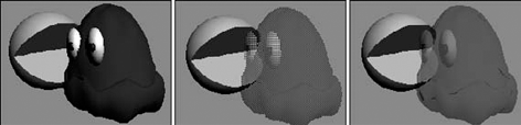
In addition to these shading types, you also can set the viewport to display objects that contain transparency (which is set in the Object Properties dialog box). The three Transparency options are None, which doesn't display any transparency; Simple, which cross-hatches the transparent object; and Best, which includes a transparency effect for a smooth look. Figure 2.18 shows these three transparency options with the help of a hungry little animated creature and his ghostly rival.
The Rendering Options section within the Rendering Method panel includes several other options, such as Disable View (D) and Disable Textures. These options can help speed up viewport updates or increase the visual detail of the objects in the viewport.
Tip
At any time during a viewport update, you can click the mouse or press a key to cancel the redraw. Max doesn't make you wait for a screen redraw to be able to execute commands with the mouse or keyboard shortcuts.
The Disable Textures option turns off texture rendering for quick viewport updates. The Texture Correction option speeds rendering updates by interpolating the current texture rather than re-rendering. Texture Correction (along with Disable View and Viewport Clipping) is one of the options available in the pop-up menu by right-clicking the viewport name.
A z-buffer is an area of memory used to keep track of each object's distance from the camera. Enabling Z-Buffer Wireframe Objects causes the wireframe objects to be drawn from back to front. If your wireframe lines seem to be disappearing, it could be that the viewport is drawing the lines in whatever order and some lines that should appear in the back are being drawn on top of the ones in the front. Enabling this option helps prevent that.
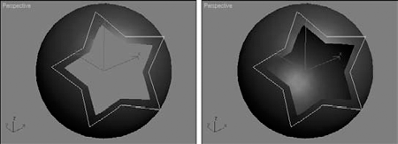
Force 2-Sided makes both sides of all faces visible. For example, suppose you have a sphere with a hole in it. This setting enables you to see the interior surface of the sphere through the hole. Figure 2.19 shows a sphere with a star-shape cutout of its surface. The left image has the Force 2-Sided option disabled, and the image on the right has it enabled.
The Default Lighting toggle deactivates your current lights and uses the default lights. This option can be helpful when you're trying to view objects in a dark setting because the default lighting illuminates the entire scene without requiring you to remove or turn off lights. You can also specify whether default lighting uses one light or two. The one-light option creates a single light positioned behind the viewer and at an angle to the scene. Scenes with one light update quicker than scenes with two lights.
You use Shade Selected Faces (F2) to shade selected subobject faces in red, making them easy to see.
Note
The Shade Selected Faces (F2) option, which shades selected subobject faces, is different from the Views
The Use Selection Brackets option displays white corners around the current selection. Selection brackets are useful for helping you see the entire size of a grouped object but can be annoying if left on with many objects selected. Uncheck this option (or press the J key) to make these brackets disappear.
The option to Display Selected with Edged Faces helps to highlight the selected object. If this option is enabled, then the edges of the current selection are displayed regardless of whether the Edged Faces check box is enabled. Figure 2.20 shows the grips of an M-203 rifle that was created by Viewpoint Datalabs selected with the Display Selected with Edged Faces and the Use Selection Brackets options enabled. These options make the current selection easy to see.
Clipping planes define an invisible barrier beyond which all objects are invisible. For example, if you have a scene with many detailed mountain objects in the background, working with an object in the front of the scene can be difficult. By setting the clipping plane between the two, you can work on the front objects without having to redraw the mountain objects every time you update the scene. This affects only the viewport, not the rendered output.

Figure 2.20. The Display Selected with Edged Faces and Use Selection Brackets options make identifying the current selection easy.
Enabling the Viewport Clipping option places a yellow line with two arrows on the right side of the viewport, as shown in Figure 2.21. The top arrow represents the back clipping plane, and the bottom arrow is the front clipping plane. Drag the arrows to set the clipping planes. You can quickly turn Viewport Clipping on or off by right-clicking the viewport name and choosing Viewport Clipping from the pop-up menu.
The Fast View option speeds viewport updates by drawing only a limited number of faces. The spinner value determines how often faces are drawn. For example, a setting of 5 would draw only every fifth face. This option renders viewport updates much quicker and gives you an idea of the objects without displaying the entire object.

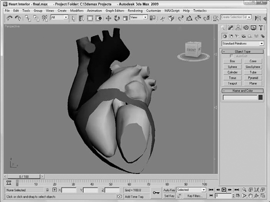
You can use the Clipping Planes setting in the Viewport Configuration dialog box to view the interior of a model such as this heart model created by Viewpoint.
To view the interior of a heart model, follow these steps:
Open the Heart interior.max file from the Chap 02 directory on the DVD.
Choose Customize
The Clipping Plane markers appear to the right of the viewport. The top marker controls the back clipping plane, and the bottom marker controls the front clipping plane. Drag the bottom clipping plane marker upward to slice through the heart model to reveal its interior, as shown in Figure 2.22.
You can also alter the Field of View (FOV) for the Perspective view in the Viewport Configuration dialog box. To create a fish-eye view, increase the FOV setting to 10 or less. The maximum FOV value is 180, and the default value is 45. You can also change the Field of View using the Field of View button in the Viewport Navigation Controls. The Viewport Configuration dialog box, however, lets you enter precise values.
Note
See Chapter 18, "Configuring and Aiming Cameras," for more coverage on Field of View.

Now that you've started to figure out the viewports, you may want to change the number and size of viewports displayed. The Layout panel, shown in Figure 2.24, in the Viewpoint Configuration dialog box, offers several layouts as alternatives to the default layout (not that there is anything wrong with the default and its four equally sized viewports).

After selecting a layout from the options at the top of the panel, you can assign each individual viewport a different view by clicking on each viewport in the Layout panel and choosing a view from the pop-up menu. The view options include Perspective, User, Front, Back, Top, Bottom, Left, Right, ActiveShade, Track, Schematic, Grid (Front, Back, Top, Bottom, Left, Right, Display Planes), Extended (Asset Browser, Motion Mixer, Biped Animation WorkBench, MAXScript Listener), and Shape. All of these view options are also available by right-clicking on the viewport title in the upper-left corner of the viewport. Figure 2.25 shows a viewport layout with the Track view, Schematic view, Asset Browser, and Perspective views open.

Figure 2.25. Other interfaces such as the Track view, Schematic view, and Asset Browser can be opened within a viewport.
Views can also be set to Camera and Spotlight if they exist in the scene. Each camera and light that exists is listed by name at the top of the pop-up menu.
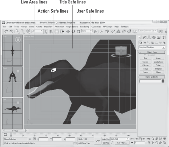
Completing an animation and converting it to some broadcast medium, only to see that the whole left side of the animation is being cut off in the final screening, can be discouraging. If you rely on the size of the active viewport to show the edges of the final output, you could be way off. Using the Safe Frames feature, you can display some guides within the viewport that show where these clipping edges are.
The Safe Frames panel of the Viewport Configuration dialog box lets you define several safe frame options, as shown in Figure 2.26, including the following:
Live Area: Marks the area that will be rendered, shown as yellow lines. If a background image is added to the viewport and the Match Rendering Output option is selected, then the background image will fit within the Live Area.
Action Safe: The area ensured to be visible in the final rendered file, marked with light blue lines; objects outside this area will be at the edge of the monitor and could be distorted.
Title Safe: The area where the title can safely appear without distortion or bleeding, marked with orange lines.
User Safe: The output area defined by the user, marked with magenta lines.
12-Field Grid: Displays a grid in the viewport, marked with a pink grid.
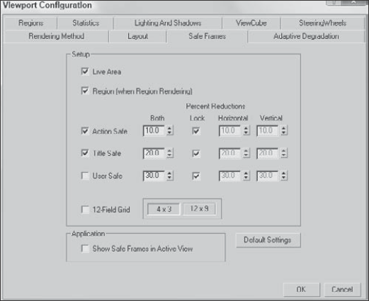
For each type of safe frame, you can set the percent reduction by entering values in the Horizontal, Vertical, or Both fields. The 12-Field Grid option offers 4×3 and 12×9 aspect ratios.
The Show Safe Frames in Active View option displays the Safe Frame borders in the active viewport. You can quickly enable or disable Safe Frames by right-clicking the viewport name and choosing Show Safe Frame in the pop-up menu (or you can use the Shift+F keyboard shortcut).
Figure 2.27 shows an elongated Perspective viewport with all the safe frame guides enabled. The Safe Frames show that the top and bottom of my dinosaur will be cut off when rendered.
When you are previewing a complex scene with hundreds of objects in a viewport, updating the viewport can slow to a crawl. This can make viewing your work difficult and slow. The feature in Max that addresses this issue is called Adaptive Degradation, and although it sounds like a weapon that some alien might use to disarm you, it enables you to force a viewport to display at a pre-specified number of frames per second. If the display update takes too long to maintain the goal frames per second rate, then it automatically degrades the rendering level in order to maintain the frame rate. This option is very helpful because when you're testing an animation, you are not as concerned about the model details or textures.
The Adaptive Degradation panel is available in the Viewport Configuration dialog box, as shown in Figure 2.28.
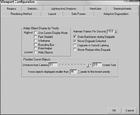
Figure 2.28. The Adaptive Degradation panel maintains a defined frame rate by degrading the rendering level.
Tip
Right-clicking on the Adaptive Degradation button opens the Adaptive Degradation panel in the Viewport Configuration dialog box.
The Adapt Object Display by Priority section contains several display options listed in order from the most difficult to render (Use Current Display Mode) to the easiest (Hide Objects). Every display option that is selected can be used during the degrade process. For example, if the Fast Shaded, Wireframe, and Bounding Box options are enabled, and if the viewport is having trouble updating, then the prioritized objects are displayed using the Bounding Box rendering method and other objects are displayed using the Wireframe or Fast Shaded methods. If the display is still below the target frames per second, then more prioritized objects are degraded to the Bounding Box method.
Different scene objects can degrade to different levels based on their priority. Object priority is set using a slider, which can be based on the object's distance from the camera, and Screen Size, which equates to the object's size in the viewport. If the slider is all the way to the left, then objects farther from the front of the scene are degraded first. If the slider is all the way to the right, then smaller objects are degraded first. Another option can force all objects smaller than a designated size to the lowest enabled display setting.
In the Maintain Frames Per Second field, you enter the frame rate that you want to maintain.
Note
Remember that film generally runs at 24 fps, television at 30 fps, Web animations at 12 fps, and high-res games at 60 fps.
The FPS setting includes several options. The Draw Backfaces during Degrade option causes all object backfaces to appear. The Never Degrade Selected option keeps the selected object from changing its display and is a helpful option if you want a main character to remain displayed in its current display mode.
Tip
If you have another unselected object in the scene that you want to keep visible, you can enable the Never Degrade option in the Object Properties dialog box. This option prevents the object from being degraded.
The Degrade to Default Lighting option turns off all lighting effects, which can be a display bottleneck and uses only default lighting. The Never Redraw After Degrade option prevents the viewports from being refreshed when the mouse button is released while Adaptive Degradation is enabled.
Tip
Another way to speed the frame rate in the active viewport is to disable (D) the inactive viewports.
To enable Adaptive Degradation in the viewports, follow these steps:
Open the Delfino Feroce 2001.max file from the Chap 02 directory on the DVD.
This file includes a realistic car model created by Viewpoint Datalabs.
Select the Edit
Hold down the Shift key and drag the car with the Select and Move tool. In the Clone Options dialog box that opens, enter a value of 5 for the Number of Copies. If your computer is fast enough to display all copies of the car without any trouble, try increasing the number of copies.
This creates five more copies of the selected car.
Right-click on the Adaptive Degradation button at the bottom of the interface. In the Adaptive Degradation panel of the Viewport Configuration dialog box, set the Maintain Frames Per Second value to 25, enable the Use Current Display Mode, Wireframe, and Bounding Box options, and drag the slider to the left to the Distance from Camera side. Then click OK. Click on the Adaptive Degradation button to enable it.
The Adaptive Degradation button turns yellow when enabled.
Click on the Arc Rotate button in the Viewport Navigation Controls and drag in the viewport.
Notice how the cars farthest from the camera are degraded to bounding boxes.
Right-click on the Adaptive Degradation button again and drag the slider all the way to the right so that Screen Size affects what is degraded. Then close the Viewport Configuration dialog box and drag in the viewport again.
Notice this time how the smaller objects are degraded, as shown in Figure 2.29.
Tip
Pressing the 7 key enables statistics mode in the viewport so you can see in real time the frames per second.
The Regions panel enables you to define regions and focus your rendering energies on a smaller area. Complex scenes can take considerable time and machine power to render. Sometimes, you want to test render only a portion of a viewport to check material assignment, texture map placement, or lighting.
You can define the size of the various Regions in the Regions panel of the Viewport Configuration dialog box, shown in Figure 2.30.
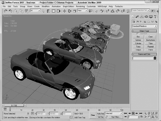
Figure 2.29. Smaller objects are degraded to wireframe and bounding boxes based on their size in the current viewport.
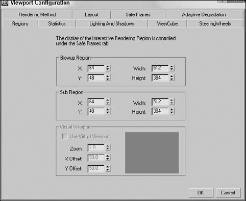
After you've specified a Blowup Region or a Sub Region, you can select to render using these regions by selecting Region or Blowup from the Render Type drop-down list on the far-right end of the main toolbar and clicking the Quick Render button. After clicking the Quick Render button, the specified region is displayed as an outline in the viewport and an OK button appears in the lower-right corner of the viewport. You can move this outline to reposition it or drag its edge or corner handles to resize the region. The new position and dimension values are updated in the Regions panel for next time. Click OK to begin the rendering process.
The difference between these two regions is that the Sub Region displays the Rendered Frame Window in black, except for the specified sub-region. The Blowup Region fills the entire Rendered Frame Window, as shown in Figure 2.31.
Note
You can learn more about Render Types and the Rendered Frame Window in Chapter 22, "Learning to Render a Scene."
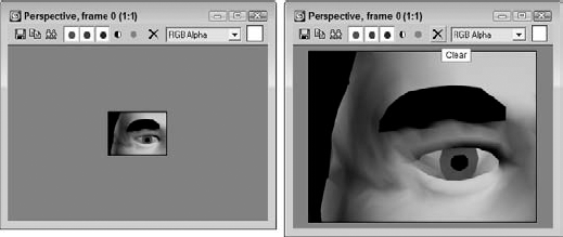
Figure 2.31. The image on the left was rendered using the Sub Region option; the right image used the Blowup Region.
The Virtual Viewport is a feature that lets you zoom in and pan within the viewport image using the numeric keypad. This feature is available only if you are using the OpenGL display driver. You can check to see which display driver you are using by selecting Help
If you have OpenGL set as the current display driver, then you can select Use Virtual Viewport to display the viewport in the area to the right. Using the Zoom, X, and Y Offset values, you can specify where the virtual viewport looks or you can drag the rectangular outline in the visible screen to the right.
Once the Virtual Viewport feature is enabled, you can use the divide key (/) on the numeric keypad to turn the virtual viewport on and off. Use the plus (+) and minus (−) numeric keypad keys to zoom in and out, and use the 2, 4, 6, and 8 keys on the numeric keypad to pan within the virtual viewport.
Warning
The Virtual Viewport feature is available only if you are using the OpenGL driver. If you've specified either the Software Z-Buffer or the Direct X driver, then this option isn't available.
The Statistics panel, shown in Figure 2.32, lets you display valuable statistics in the viewport window. These statistics can include Polygon Count, Triangle Count, Edge Count, Vertex Count, and Frames Per Second. You can also select to view these statistics for all the objects in the scene (Total), for just the selected object, or for both. You can toggle statistics on and off for the active viewport using the 7 key.
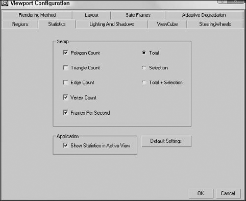
Figure 2.32. The Statistics panel lets you display polygon count and frames per second in the viewport.
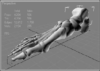
By enabling the Show Statistics in Active View option, the selected statistics are overlaid on the active viewport, as shown in Figure 2.33.
Remember in grade school when you realized that you could immediately draw really well using tracing paper (where all you needed to do was follow the lines)? Well, it's not quite tracing paper, but you can load background images into a viewport that can help as you create and position your objects.
The Views
If the background image changes, you can update the viewport using the Views
The Files button opens the Select Background Image dialog box, where you can select the image to load. The Devices button lets you obtain a background from a device such as a Video Recorder. If an environment map is already loaded into the Environment dialog box, you can simply click the Use Environment Background option. Keep in mind that the background image will not be rendered unless it is made into an Environment map.
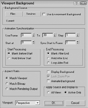
Figure 2.34. The Viewport Background dialog box lets you select a background source image or animation.
Note
Environment maps are covered in Chapter 2, "Learning to Render a Scene."
The Animation Synchronization section of the Viewport Background dialog box lets you set which frames of a background animation sequence are displayed. The Use Frame and To values determine which frames of the loaded animation are used. The Step value trims the number of frames that are to be used by selecting every Nth frame. For example, a Step value of 4 would use every fourth frame.
Tip
Loading an animation sequence as a viewport background can really help as you begin to animate complex motions, like a running horse. By stepping through the frames of the animation, you can line up your model with the background image for realistic animations.
The Start At value is the frame in the current scene where this background animation would first appear. The Sync Start to Frame value is the frame of the background animation that should appear first. The Start and End Processing options let you determine what appears before the Start and End frames. Options include displaying a blank, holding the current frame, and looping.
If you select an animation as the background, make sure that the Animate Background option is selected. Also note that the viewport background is not visible if the Display Background option is not selected.
The Aspect Ratio section offers options for setting the size of the background image. You can select to Match Viewport, Match Bitmap, or Match Rendering Output.
The Lock Zoom/Pan option is available if either the Match Bitmap option or the Match Rendering Output option is selected. This option locks the background image to the geometry so that when the objects in the scene are zoomed or panned, the background image follows. If the background gets out of line, you can reset its position with the Views
Warning
When the Lock Zoom/Pan option is selected, the background image is resized when you zoom in on an object. Resizing the background image fills the virtual memory, and if you zoom in too far, the background image could exceed your virtual memory. If this happens, a dialog box appears to inform you of the problem and gives you the option of not displaying the background image.
You can set the Apply Source and Display to option to display the background in All Views or in the active viewport only.
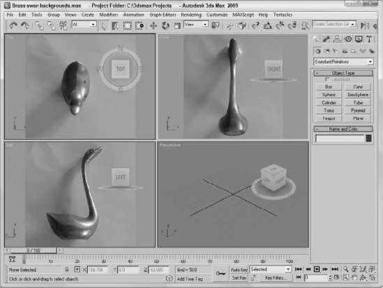
When modeling a physical object, you can get a jump on the project by taking pictures with a digital camera of the front, top, and left views of the object and then load them as background images in the respective viewports. The background images can then be a reference for your work. This is especially helpful with models that need to be precise. You can even work from CAD drawings.
To load the background images of a brass swan, follow these steps:
Choose File
Right-click on the Front viewport to make it the active viewport, and choose Views
The Viewport Background dialog box opens.
Click on the Files button, and in the File dialog box that opens, select the Brass swan-front view.jpg image from the Chap 02 directory on the DVD.
Select the Match Bitmap, Display Background, Lock Zoom/Pan, and Active Only options, and click OK to close the dialog box.
The image now appears in the background of the Front viewport.
Repeat Steps 2 through 4 for the Top and Left viewports.
Figure 2.35 shows the Max interface with background images loaded in the Front, Top, and Left viewports.
Viewports are the window into the Max world. Remember that if you can't see it, you can't work with it, so you need to learn to use the viewports. You can also configure viewports to display just the way you desire.
This chapter covered the following topics:
3D space and the various viewport types
Using the ViewCube and the SteeringWheels
The various Viewport Navigation Control buttons
The Rendering Level and Display options in the Viewport Configuration dialog box
The other panels of the Viewport Configuration dialog box that allow you to change the layout, safe frames, regions, statistics, and viewport shading options
How to use Adaptive Degradation to maintain a constant frame rate for viewports
A viewport background image
In the next chapter, you find out all the details about working with files, including loading, saving, and merging scene files. The next chapter also covers import and export options for interfacing with other software packages.