
This chapter covers the following topics:
802.11 WLANs are becoming pervasive in network deployments primarily because they are easy to implement and easy to use. From the perspective of the user, they function and perform exactly like a shared Ethernet LAN. Ironically, the 802.11 architecture is anything but simple. The challenges of an uncontrolled medium are more complex than those of the controlled wired Ethernet medium.
The 802.11 MAC must orchestrate an access mechanism that allows fair access to the medium. 802.11 stations do not possess the ability to sense collisions that the carrier sense multiple access/collision detect (CSMA/CD)–based wired Ethernet stations do. As a result, a more robust and scalable MAC is required for medium access with minimized overhead.
This chapter provides an overview of the 802.11 basic access mechanism.
802.11 networks are flexible by design. You have the option of deploying three types of WLAN topologies:
A service set is a logical grouping of devices. WLANs provide network access by broadcasting a signal across a wireless radio frequency (RF) carrier. A receiving station can be within range of a number of transmitters. The transmitter prefaces its transmissions with a service set identifier (SSID). The receiver uses the SSID to filter through the received signals and locate the one it wants to listen to.
An IBSS consists of a group of 802.11 stations communicating directly with one another. An IBSS is also referred to as an ad-hoc network because it is essentially a simple peer-to-peer WLAN. Figure 2-1 illustrates how two stations equipped with 802.11 network interface cards (NICs) can form an IBSS and communicate directly with one another.

A BSS is a group of 802.11 stations communicating with one another. A BSS requires a specialized station known as an access point (AP). The AP is the central point of communications for all stations in a BSS. The client stations do not communicate directly other client stations. Rather, they communicate with the AP, and the AP forwards the frames to the destination stations. The AP might be equipped with an uplink port that connects the BSS to a wired network (for example, an Ethernet uplink). Because of this requirement, a BSS is also referred to as an infrastructure BSS. Figure 2-2 illustrates a typical infrastructure BSS.
Multiple infrastructure BSSs can be connected via their uplink interfaces. In the world of 802.11, the uplink interface connects the BSS to the distribution system (DS). The collection of BSSs interconnected via the DS is known as the ESS. Figure 2-3 shows a practical implementation of an ESS. The uplink to the DS does not have to be via a wired connection. The 802.11 specification leaves the potential for this link to be wireless. For the most part, DS uplinks are wired Ethernet.

Chapter 1, “Ethernet Technologies,” described CSMA/CD as the medium access mechanism for 802.3-based Ethernet networks. 802.11-based WLANs use a similar mechanism known as carrier sense multiple access with collision avoidance (CSMA/CA). CSMA/CA is a listen before talk (LBT) mechanism. The transmitting station senses the medium for a carrier signal and waits until the carrier channel is available before transmitting.
Wired Ethernet is able to sense a collision on the medium. Two stations transmitting at the same time increase the signal level on the wire, indicating to the transmitting stations that a collision has occurred. 802.11 wireless stations do not have this capability. The 802.11 access mechanism must make every effort to avoid collisions altogether.
Chapter 1 compares CSMA/CD to a telephone conference call. Each participant wanting to speak needs to wait for everyone else to stop speaking. Once the line is quiet, the participant can attempt to speak. If two participants begin speaking at the same time, they must stop and try again.
CSMA/CA is more ordered than CSMA/CD. To use the same telephone conference call analogy, you make some changes to the scenario:
Before a participant speaks, she must indicate how long she plans to speak. This indication gives any potential speakers an idea of how long to wait before they have an opportunity to speak.
Participants cannot speak until the announced duration of a previous speaker has elapsed.
Participants are unaware whether their voices are heard while they are speaking, unless they receive confirmation of their speeches when they are done.
If two participants happen to start speaking at the same time, they are unaware they are speaking over each other. The speakers determine they are speaking over each other because they do not receive confirmation that their voices were heard.
The participants wait a random amount of time and attempt to speak again, should they not receive confirmation of their speeches.
As you can see, CSMA/CA has more stringent rules than CSMA/CD. These rules help prevent collisions. This prevention is key for wireless networks because there is no explicit collision-detection mechanism. CSMA/CA implicitly detects a collision when a transmitter does not receive an expected acknowledgment.
The 802.11 implementation of CSMA/CA is manifested in the distributed coordination function (DCF). To describe how CSMA/CD works, it is important to describe some key 802.11 CSMA/CA components first:
Carrier sense
DCF
Acknowledgment frames
Request to Send/Clear to Send (RTS/CTS) medium reservation
In addition, two other mechanisms pertain to 802.11 medium access but are not directly tied to CSMA/CA:
Frame fragmentation
Point coordination function (PCF)
A station that wants to transmit on the wireless medium must sense whether the medium is in use. If the medium is in use, the station must defer frame transmission until the medium is not in use. The station determines the state of the medium using two methods:
Check the Layer 1 physical layer (PHY) to see whether a carrier is present.
Use the virtual carrier-sense function, the network allocation vector (NAV).
The station can check the PHY and detect that the medium is available. But in some instances, the medium might still be reserved by another station via the NAV. The NAV is a timer that is updated by data frames transmitted on the medium. For example, in an infrastructure BSS, suppose Martha is sending a frame to George (see Figure 2-4). Because the wireless medium is a broadcast-based shared medium, Vivian also receives the frame. The 802.11 frames contain a duration field. This duration value is large enough to cover the transmission of the frame and the expected acknowledgment. Vivian updates her NAV with the duration value and does not attempt transmission until the NAV has decremented to 0.
Note that stations only update the NAV when the duration field value received is greater than what is currently stored in their NAV. Using the same example, if Vivian has a NAV of 10 milliseconds, she does not update her NAV if she receives a frame with a duration of 5 milliseconds. She updates her NAV if she receives a frame with a duration of 20 milliseconds.
The IEEE-mandated access mechanism for 802.11 networks is DCF, a medium access mechanism based on the CSMA/CA access method. To describe DCF operation, we first define some concepts. Figure 2-5 shows a time line for the scenario in Figure 2-4.
In DCF operation, a station wanting to transmit a frame must wait a specific amount of time after the medium becomes available. This time value is known as the DCF interframe space (DIFS). Once the DIFS interval elapses, the medium becomes available for station access contention.
In Figure 2-5, Vivian and George might want to transmit frames when Martha's transmission is complete. Both stations should have the same NAV values, and both will physically sense when the medium is idle. There is a high probability that both stations will attempt to transmit when the medium becomes idle, causing a collision. To avoid this situation, DCF uses a random backoff timer.
The random backoff algorithm randomly selects a value from 0 to the contention window (CW) value. The default CW values vary by vendor and are value-stored in the station NIC. The range of values for random backoff start at 0 slot times and increment up to the maximum value, which is a moving ceiling starting at CWmin and stopping at a maximum value known as CWmax. For the sake of this example, assume that the CWmin value begins at 7 and CWmax value is 255. Figure 2-6 illustrates the CWmin and CWmax values for binary random backoff.
A station randomly selects a value between 0 and the current value of the CW. The random value is the number of 802.11 slot times the station must wait during the medium idle CW before it may transmit. A slot time is a time value derived from the PHY based on RF characteristics of the BSS .
Getting back to the example, Vivian is ready to transmit. Her NAV timer has decremented to 0, and the PHY also indicates the medium is idle. Vivian selects a random backoff time between 0 and CW (in this case, CW is 7) and waits the selected number of slot times before transmitting. Figure 2-7 illustrates this process, with a random backoff value of four slot times.
Once the four slot times pass, Vivian can transmit. But what if George's station has a random backoff time of two time slots? Vivian hears a new duration from George's frame when he begins his transmission, and Vivian updates her NAV with that new value. Vivian must wait for her NAV to decrement to 0 and her PHY to report that the medium is available again before she can resume her backoff. (In this example, Vivian must wait an additional two slot times before attempting to transmit.)
Assuming that Vivian is able to defer transmission for all four slot times, she transmits the frame. So how does Vivian know that the frame made it to its destination? The 802.11 specification requires that the receiving station send an acknowledgment frame to the frame sender. This acknowledgment frame allows the sending station to indirectly determine whether a collision took place on the medium. If the sending station does not receive an acknowledgment frame, it assumes that a collision occurred on the medium. The sending station updates its retry counters, doubles the CW value, and begins the medium access process again. Figure 2-8 summarizes the steps a DCF station must iterate through to transmit a frame.
A station receiving a frame acknowledges error-free receipt of the frame by sending an acknowledgment frame back to the sending station. Knowing that the receiving station has to access the medium and transmit the acknowledgment frame, you would assume that it is possible for the acknowledgment frame to be delayed because of medium contention. The transmission of an acknowledgment frame is a special case. Acknowledgment frames are allowed to skip the random backoff process and wait a short interval after the frame has been received to transmit the acknowledgment. The short interval the receiving station waits is known as the short interframe space (SIFS). The SIFS interval is shorter than a DIFS interval by two slot times. It guarantees the receiving station the best possible chance of transmitting on the medium before another station does.
Referring to Vivian's transmission to George, Vivian deferred her transmission attempt for four slot times. The medium was still available, so she transmitted her frame to George, as depicted in Figure 2-9. The AP receives the frame and waits a SIFS interval before sending an acknowledgment frame.
Supposing that Vivian never receives an acknowledgment frame, she doubles the CW value to 15 and repeats the backoff process. For every medium access attempt that fails, the 802.11 station increments a retry counter. CW continues to double until it is equal to CWmax. The MAC layer may continue to attempt to transmit the frame, but once the frame retry counters reach a administrator-defined retry threshold, Vivian's station attempts to reserve the medium.
Vivian might be unable to access the medium because of another station that is within range of the AP yet out of range of her station. Figure 2-10 illustrates this situation. Vivian and George are in range of each other and in range of the AP. Yet neither of them is in range of Tony. Tony is in range of the AP and attempts to transmit on the medium as well. The situation is known as the hidden node problem because Tony is hidden to Vivian and George.

Vivian attempts to reserve the medium using a special control frame known as an RTS frame. The RTS frame is sent to the AP and indicates to the AP, and all stations that are within range of Vivian, the expect duration of Vivian's frame exchange. The frame exchange includes the frame she wants to initially transmit as well as the expected acknowledgment frame.
The AP receives Vivian's RTS frame and reply with a CTS control frame. The CTS frame contains a duration field value long enough to allow Vivian to complete her frame exchange. All stations within range of the AP, including Tony and George, receive the CTS frame and update their NAVs, as illustrated in Figure 2-11.

The initial RTS frame that Vivian transmits must go through the DCF process, as would any normal frame. But similar to the acknowledgment frame, the corresponding CTS frame from the AP skips the random backoff procedure and only needs to wait the SIFS interval before being transmitted. Figure 2-12 details Vivian's RTS frame transmission. Both George and Tony update their NAVs accordingly, but the acknowledgment frame the AP sends back to Vivian does not have to conform to the DCF rules. When George receives the frame, George immediately sends back an acknowledgment frame. Although George's NAV is nonzero, he still sends an acknowledgment frame back to the AP after a SIFS interval.
Frame fragmentation is a MAC layer function that is designed to increase the reliability of frame transmission across the wireless medium. The premise behind fragmentation is that a frame is broken up into smaller fragments, and each fragment is transmitted individually, as depicted in Figure 2-13. The assumption is that there is a higher probability of successfully transmitting a smaller frame fragment across the hostile wireless medium. Each frame fragment is individually acknowledged; therefore, if any fragment of the frame encounters any errors or a collision, only the fragment needs to be retransmitted, not the entire frame, increasing the effective throughput of the medium.

The network administrator can define the fragment size (see Figure 2-14). Fragmentation occurs only on unicast frames. Broadcast or multicast frames are transmitted as a whole. Also, the frame fragments are sent as a burst, using a single iteration of the DCF medium access mechanism.

Although fragmentation can increase the reliability of frame transmission in a WLAN, it does increase the 802.11 MAC protocol overhead. Every frame fragment includes the 802.11 MAC header information as well as require a corresponding acknowledgment frame. This increase in MAC overhead decreases the actual wireless station throughput. Fragmentation is a balance between medium reliability and medium overhead.
PCF is an 802.11 optional medium access mechanism that is used in addition to DCF. PCF is an access mechanism that provides contention-free frame delivery to and from the AP. Most vendors do not include PCF support because it increases the protocol overhead of the BSS. As a result, it is not widely deployed. Forthcoming quality-of-service (QoS) enhancements to the 802.11 specification build on PCF to create a more useful mechanism.
This section covers PCF operation, detailing the operation of the point coordinator (PC) and PCF-aware stations (referred to as CF-Pollable stations in the 802.11 specification).
The Contention Free Period (CFP) is the window of time for PCF operation. The CFP begins at set intervals following a beacon frame containing a delivery traffic indication map (DTIM) information element (described later in the chapter). The frequency of CFPs is determined by the network administrator. Once the CFP begins, the AP assumes the role of the PC (and as such, PCF operation is only supported in infrastructure BSSs). Each 802.11 client sets its NAV to the CFPMaxDuration value. This value is included in the CF parameter set information element (detailed later in the chapter). The CFPMaxDuration defines the time value that is the maximum duration for the CFP. The PC can end the CFP before the CFPMaxDuration time elapses. The AP transmits beacon frames at regular intervals, and beacon frames sent during the CFP contain the CFPDurationRemaining field to update station NAVs of the remaining duration of the CFP. Figure 2-15 depicts the CFP and contention period (CP) as a function of time.
Unlike DCF operation, PCF does not allow stations to freely access the medium and transmit data. Stations can only send data (one frame at a time) when the PC polls them. The PC can send frames to stations, poll stations for frame transmission, acknowledge frames requiring MAC-level acknowledgments, or end the CFP.
When the CFP begins, the PC must access the medium in the same manner as a DCF station. Unlike DCF stations, the PC attempts to access the medium after waiting an interval of time known as the priority interframe space (PIFS). The PIFS interval is one slot time longer than the SIFS interval and one slot time shorter than the DIFS interval, allowing PCF stations to access the medium before DCF stations yet still allowing control frames, such as acknowledgment frames, to have the highest probability of gaining access to the medium. Figure 2-16 illustrate the SIFS, PIFS, DIFS, and slot time relationships.

After waiting a PIFS interval, the PC sends the initial beacon frame containing the CF parameter information element. The PC waits for one SIFS interval subsequent to the beacon frame transmission and then sends one of the following to a CF-Pollable station:
A data frame
A poll frame (CF-Poll)
A combination data and poll frame (Data+CF-Poll)
A CFP end frame (CF-End)
If the PC has no frames to send and no CF-Pollable stations to poll, the CFP is considered null, and immediately following the beacon frame, the PC sends a CF-End frame terminating the CFP.
Continuing the same example as before, Vivian, Martha, and George are communicating with AP1. Figure 2-17 depicts this example.
AP1 sends a beacon frame indicating the start of a CFP. The CFP is set for 20 seconds (sec). Vivian, Martha, and George all update their NAVs to reflect the 20-sec CFP. After waiting a SIFS interval, AP1 sends a frame buffered for Vivian's station and also sends a poll to Vivian's station to see whether she has any frames to send using the Data+CF-Poll frame. Vivian receives the Data+CF-Poll frame and sends one data frame and a contention-free acknowledgment (Data+CF-ACK) frame after waiting a SIFS interval. Note that Vivian's station ignores her NAV setting when transmitting frames in response to a CF-Poll frame.
AP1 iterates through its polling list to Martha's station. AP1 uses another combination frame to send a data frame to Martha, acknowledge Vivian's frame, and poll Martha's station for frame transmission (Data+CF-ACK+CF-Poll). Note that the frame is destined for Martha's station, yet it acknowledges Vivian's last frame. The multiple access nature of 802.11 allows for this arrangement. Martha waits a SIFS interval and sends a Data+CF-ACK frame.
AP1 finally iterates to George's station. The AP has no data frames buffered for George's station, so it sends a CF-Poll frame to see whether George has any frames to send. George has no frames buffered either, so George sends a null data frame. Although the CFP has not exceeded the maximum duration allowed, AP1 sends a CF-End frame to end the CFP and proceed to the CP and normal DCF medium access. Vivian, Martha, and George receive the CF-End frame and reset their NAVs.
Although the previous section described how 802.11-standards–based devices access the wireless medium, this section discusses devices that fall outside of the 802.11 standard. These devices use the 802.11 technology in a way that violates or extends an area of the standard and that might prove useful in your network. The specific devices under consideration are
Repeater APs
Universal clients (workgroup bridges)
Wireless bridges
Although each of these devices provides useful networking tools, you should remember that they are not currently defined in the 802.11 standard, and there are no interoperability guarantees because different vendors may define different mechanisms for implementing these tools. For the reliability of your network, should you choose to use these, you should ensure that they are only interfacing to devices from the same vendor or devices for which the vendor ensures interoperability.
You might find yourself in situations where it is not easy or convenient to connect an AP to the wired infrastructure or where an obstruction makes it difficult for an AP on your wired network to directly associate clients in an area of your deployment. In such a scenario, you can employ a repeater AP. Figure 2-18 shows this scenario, where Elaine is not directly visible to AP2 but she can see AP3, which is not connected to the wired network but can see AP2.
Much like a wired repeater, what a wireless repeater does is merely retransmit all the packets that it receives on its wireless interface. This retransmission happens on the same channel upon which the packet was received. The repeater AP has the effect of extending the BSS and also the collision domain. Although it can be an effective tool, you must take care when employing it; the overlapping of the broadcast domains can effectively cut your throughput in half because the originating AP also hears the retransmit. The problem can become even more exacerbated with a chain of repeater APs. In addition, the use of a repeater AP might limit you to utilizing clients with extensions that enable them to support associating to and running services over repeater APs. In spite of these limitations, it is highly likely that you will find applications for repeater APs in your network.
As you migrate from a wired to a wireless network architecture, you might find that you have network devices that provide a wired Ethernet or serial interface but lack an interface slot for a wireless NIC. If it would be advantageous for you to have these devices on your wireless network, you can use a universal client or workgroup bridge. This scenario is illustrated in Figure 2-19.

Examples of devices that might fall into this category include retail point-of-sale devices, printers, older PCs, copiers, and small mobile networks. The universal client or workgroup bridge encapsulates the wired packets it receives into wireless packets and thereby provides the 802.11 interface to the AP. The term universal client is most often used when a single wired device is being connected, whereas workgroup bridges are used for a small network of multiple devices. There is no standards-based approach for encapsulating or forwarding this wired interface data, so you often need to make sure that your universal client or workgroup bridge is certified to interoperate with your AP.
If you extend the concept of a workgroup bridge even further to the point where you are connecting two or more wired networks, you arrive at the concept of wireless bridges. Similar to wired bridges, wireless bridges connect networks. You might bridge wirelessly because you need to connect networks that are inherently mobile. Alternatively, the networks to be connected might not be co-located, in which case wireless bridging provides a method for connecting these networks. The main distinction between bridges and workgroup bridges is that the latter are only wirelessly enabling a small network in an office environment, whereas the former can connect larger networks often separated by distances much greater than what is found in the WLAN environment. In fact, many vendors offer products that provide ranges which far exceed the definitions and limitations of 802.11. Figure 2-20 shows a wireless bridging example.
As shown in the figure, one of the bridges assumes the role of the AP in a WLAN network, and the other bridges act as clients. Although the basic 802.11 MAC and PHY sublayer technologies are utilized in wireless bridging, individual vendors have their own proprietary methods for the encapsulation of wired network traffic and for extending the range from a MAC and PHY sublayer perspective. For this reason, once again you should ensure that your wireless bridges are certified to interoperate.
The previous section described how a station accesses and contends for the wireless medium. This section focuses on the following:
Station connectivity—. Detailed explanation of how 802.11 stations select and communicate with APs
Power save operation—. Detailed explanation of frame delivery for power save stations
802.11 frame formats—. Detailed explanation of the frame formats described in previous sections
Earlier in the chapter, we discussed how George, Martha, Vivian, and Tony shared the medium in their BSS. This section takes a step back and details how an 802.11 wireless station joins a BSS. Three exchanges take place between the wireless station and the AP:
The probe process
The authentication process
The association process
In Figure 2-21, Vivian's station is in range to three APs. Two of the APs belong to the service set marketing, and the remaining AP belongs to the service set sales. Vivian's station is configured for the service set marketing.

The client station sends an 802.11 probe request frame. Generally, an 802.11 station sends the probe request frame on every channel it is allowed to use (channels 1 through 11 in North America). This process is not mandated by the 802.11 specification. The probe request frame contains information about an 802.11 wireless station, such as which data rates the station supports and what service set the station belongs to. Figure 2-22 is a protocol decode of a probe request frame.
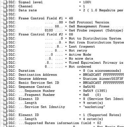
The key fields in the probe request are
SSID element—. The SSID element contains the SSID that the client station is configured with.
Support rates element—. The support rates element describes all data rates the client supports.
Client stations send probe requests frames blindly, meaning they don't know anything about the APs they are probing for. As such, most probes are sent at the lowest possible data rate of 1 Mbps. Figure 2-22 illustrates this process.
When an AP receives a probe request frame that successfully passed a frame check sequence (FCS), it replies with a probe response frame. Figure 2-23 is a protocol decode of a probe response frame.
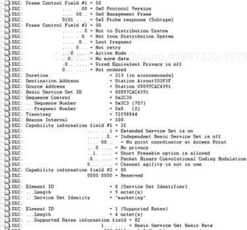
The key fields in a probe response frame follow:
Timestamp field—. The value of the TSFTIMER of the frame sender. It is used to synchronize the clock of the client station to the clock of the AP.
Beacon interval field—. The number of time units (TUs) between beacons. A TU is 1024 microseconds.
Capability information field—. MAC and PHY layer capabilities. This field is described in detail in the section, “802.11 MAC Frame Formats,” later in the chapter.
SSID element—. The SSID that the AP is configured with.
Support rates element—. All data rates that the AP supports.
PHY parameter set element—. Either frequency hopping or direct sequence. This element provides PHY-specific information to the client station. Both elements are described in detail in the section, “802.11 MAC Frame Formats,” later in the chapter.
When the client station receives the probe response frame, it is able to determine the signal strength of the received frame. The station compares the probe response frames and determines which AP to associate with. The mechanism for how a station chooses an AP to associate with is not specified by the 802.11 specification, so it is left to vendor implementation. In general, the AP selection criteria can include matching SSIDs, signal strength, and vendor proprietary extensions.
For the sake of this example, assume that matching SSIDs, supported data rates, and signal strength are the criteria (see Figure 2-24).
Table 2-1 summarizes the data from the probe response frames Vivian receives.
Table 2-1. Probe Response Information
Access Point Name | Support Data Rates | Service Set ID | Signal Strength |
|---|---|---|---|
AP1 | All | Marketing | 50% |
AP2 | All | Marketing | 100% |
AP3 | All | Sales | 20% |
Vivian is inclined to communicate with AP2. AP2 has a matching SSID, supports all data rates, and has a signal strength of 100%. AP1 is a close contender, but the signal strength is lower at 50%.
Now that Vivian's station has determined which AP to associate to, she can proceed to the next phase of station connectivity, the authentication process.
802.11 authentication consists of two authentication modes: open authentication and shared-key authentication. These two modes are detailed in Chapter 4, “802.11 Wireless LAN Security,” which covers wireless security in depth. 802.11 authentication is oriented around device authentication and determines whether the device is allowed on the network. For the purposes of this section, authentication is simplified to an authentication request and an authentication response, as depicted in Figure 2-25.

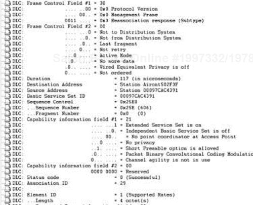
The 802.11 association process allows an AP to map a logical port or association identifier (AID) to the wireless station. The association process is initiated by the wireless station with an association request frame containing the capability information of the client and completed by the AP in an association response frame. The association response indicates success or failure as well as a reason code. Figure 2-26 is a protocol decode of an association request frame, and Figure 2-27 is a protocol decode of a association response frame.
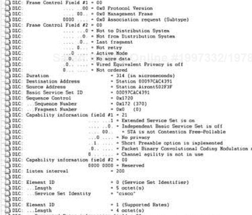

The key fields for the association request frame follow:
Listen interval—. The listen interval value is used for a power save operation and is provided by the client station to the AP. It informs the AP of how often the station will “wake up” from low-power mode to receive buffered frames from the AP. This concept is described in detail later in the chapter.
SSID element—. The SSID element specifies the client station's SSID to the AP. The AP does not normally accept association requests from stations with SSIDs differing from those configured on the AP.
Support rates element—. This element indicates what data rates the client station supports to the AP.
The key fields from the association response frame follow:
Status code—. This element indicates the status code resulting from the association response frame. All status codes are described in the section “802.11 MAC Frame Formats,” later in the chapter.
Association ID—. You can consider the AID similar to a physical port on an Ethernet hub or switch. The client station needs this value when it operates in power save mode. The AP sends notifications in beacon frames that indicate which AIDs have frames buffered. This concept is described in detail in the section, “Power Save Operation,” later in the chapter.
Support rates element—. This element indicates what data rates the AP supports.
To preserve battery life on portable WLAN clients, the 802.11 specification provides for power save operations on the clients. Power save operations have two categories:
Unicast frame operation
Multicast/broadcast frame operation
The premise behind power save (PS) operation is simple. A client station enters low-power mode by turning off its radio. The AP buffers frames destined for the station while the station is in power save mode. At a given interval, the client wakes up and listens for a beacon from the AP indicating whether frames are buffered for the client station.
Unicast power save operation uses a client-specified listen or wake-up interval. In contrast, multicast/broadcast power save operation uses an AP-defined interval, which is advertised in the AP's beacons.
The client wakes up and listens to the beacon frames to determine whether frames are buffered. If the AP does indeed have frames buffered for the client, the client polls the AP for the frames. If the AP does not have frames buffered, the client returns to low-power mode until the next wake-up interval.
When the client associates to the AP, it specifies a listen interval value in the association request frame. The listen interval is the number of beacons the client waits before transitioning to active mode. For example, a listen interval of 200 indicates that the client wakes up every 200 beacons.
The beacon frame includes a traffic indication map (TIM) information element. The element contains a list of all AIDs that have traffic buffered at the AP. There can be up to 2008 unique AIDs, so the TIM element alone can be up to 251 bytes. To minimize network overhead, the TIM utilizes a shorthand method of listing the AIDs. Figure 2-28 is a protocol decode of a beacon with a TIM indicating buffered traffic for a client.
Notice that nowhere in the protocol decode is the AID of the client station explicitly stated. To determine the AID of the client station (or stations), you need the following pieces of information:
The value of the length field
The value of the bitmap offset field
The value of the partial virtual bitmap field
802.11 specifies a traffic indication virtual bitmap as a means to indicate which station AIDs have frames buffered. The virtual bitmap starts from AID 1 to AID 2007. AID 0 is reserved for multicast/broadcast. Table 2-2 represents what a traffic indication virtual bitmap might look like. Every station with frames buffered at the AP has a flag value of 1 set for that station's AID. Stations with no frames buffered use a flag value of 0.
The partial virtual bitmap eliminates all unnecessary 0 flag values by summarizing them. All client stations that have frames buffered (and therefore have flag values of 1 in the traffic indication virtual bitmap) are included in the partial virtual bitmap. All AIDs with a flag value of 0 leading up to the partial virtual bitmap are summarized by a derived value referred to as X in the following examples. All AIDs with flag values of 0 subsequent to the partial virtual bitmap are summarized by a derived value referred to as Y in the following examples. Referring to Table 2-2, AIDs 1 through 15 are summarized by value X, and AIDs 32 through 2007 are summarized by value Y.
To calculate X and Y, you must first derive N1 and N2. The formulas for deriving N1, N2, X, and Y are as follows:
N1 = (bitmap offset * 2)
N2 = (length – 4) + N1
X = (N1 * 8) – 1
Y = (N2 + 1) * 8
In the sample decode from Figure 2-28, N1 = (1 * 2) = 2 and N2 = (5 – 4) + 2 = 3. The value X is (2 * 8) – 1 or 15, and Y is (3 + 1) * 8 or 32. X indicates that AIDs 1 through 15 all have flag values of 0, and Y indicates that AIDs 32 through 2007 also have flag values of 0.
That leaves AIDs 16 through 31, which is where the partial virtual bitmap comes into play. The partial virtual bitmap in our example is a 2 byte value, 0x0020. The first byte, 0x00 or 00000000 in binary, indicates that the next 8 station AID flags following X (AIDs 16 to 23) are all 0. The second byte is 0x20 or 00100000 in binary. So in the example, AIDs 24 to 28 have a flag value of 0 and AID 29 has a flag value of 1. Because AID 29 is the only AID with a flag value of 1, AID 29 has traffic buffered at the AP.
If the client determines that frames are buffered for it, it sends an 802.11 MAC management frame known as a power save poll (PS-Poll) frame. Figure 2-29 provides a protocol decode of the PS-Poll the client station sent in response to the beacon. Note that the AID field has a value of 29, which is what was determined to be the AID from the partial virtual bitmap in the TIM element.
The AP responds to the PS-Poll frame with one of the client's buffered frames and an indication of whether more frames are buffered. The client must send a PS-Poll frame to the AP to receive each of the buffered frames on the AP. Figure 2-29 is a protocol decode of a PS-Poll frame. Note that the AID field indicated AID 29, as was calculated in the previous example.
A broadcast power save operation has the same basic operation as unicast power save operation. The differences follow:
The administrator defines the interval for the client to wake up and receive buffered broadcast or multicast traffic on the AP.
A special TIM information element, known as a DTIM, indicates whether broadcast or multicast traffic is buffered on the AP.
Broadcast and multicast frames are buffered for all stations (including non-power–save stations) in the BSS, when one or more power save station is associated to the AP.
The TIM has two fields to indicate whether multicast/broadcast traffic is buffered and how long until it is delivered to the BSS:
DTIM count field—. This field indicates how many beacons until the delivery of buffered frames. A value of 0 indicates that the TIM is a DTIM, and if there are buffered frames, they will be transmitted immediately following the beacon.
DTIM period field—. This field indicates the number of beacons between DTIMs. For example, a value of 10 indicates that every 10th beacon will contain a DTIM.
Figure 2-30 highlights a protocol decode of a beacon containing a DTIM. In Figure 2-31, note that the frames following the beacon are all multicast frames.

There are three categories of frames in the 802.11 MAC:
All 802.11 frames leverage the 802.11 general frame. The three frames types augment and use specific portions of the general MAC frame for their specific purposes. Figure 2-32 illustrates the general MAC frame and its fields.
Frame control—. The frame control field is a 2 byte value of 11 subfields. Figure 2-33 illustrates the frame control subfields, and Figure 2-34 is a protocol decode of the frame control subfields.
The list that follows describes the 11 frame control subfields:
Protocol version—. This field specifies the version of 802.11 MAC protocol. To date, there is only one version, so the only valid value is 0. All other values are reserved.
Type—. This field specifies the type of MAC frame: control, management, or data. The fourth value is reserved.
Subtype—. This field specifies the frame subtype. These values are listed in Table 2-3.
Table 2-3. Frame Types and Subtypes
Type Value (Bit 3, Bit 2)
Type Description
Subtype Value (Bit 7, Bit 6, Bit 5, Bit 4)
Subtype Description
00
Management
0000
Association request
00
Management
0001
Association response
00
Management
0010
Reassociation request
00
Management
0011
Reassociation response
00
Management
0100
Probe request
00
Management
0101
Probe response
00
Management
0110–0111
Reserved
00
Management
1000
Beacon
00
Management
1001
Announcement traffic indication frame (ATIM)
00
Management
1010
Disassociation
00
Management
1011
Authentication
00
Management
1100
Deauthentication
00
Management
1101–1111
Reserved
01
Control
0000–1001
Reserved
01
Control
1010
01
Control
1011
RTS
01
Control
1100
CTS
01
Control
1101
Acknowledgment (ACK)
01
Control
1110
CF-End
01
Control
1111
CF-End+CF-Ack
10
Data
0000
Data
10
Data
0001
Data+CF-Ack
10
Data
0010
Data+CF-Poll
10
Data
0011
Data+CF-Ack+CF-Poll
10
Data
0100
Null function (no data)
10
Data
0101
CF-Ack (no data)
10
Data
0110
CF-Poll (no data)
10
Data
0111
CF-Ack+CF-Poll (no data)
10
Data
1000–1111
Reserved
11
Reserved
0000–1111
Reserved
To DS—. This field indicates whether the frame is destined for the DS.
From DS—. This field indicates whether the frame is sourced from the DS.
More fragments—. This field indicates whether this frame is the only management or data frame or whether other fragments should be expected.
Retry—. This field indicates whether this frame is being retransmitted. It allows the receiver to discard duplicate frames.
Power management—. Indicates the power save mode of the station. A value of 1 indicates the station is in power save mode, and a value of 0 indicates the station is in active mode. Frames from the AP always have a value of 0.
More data—. When the bit for this field is set, the receiving station is notified that it has data destined for it buffered at the AP.
WEP—. This field indicates whether Wired Equivalent Privacy (WEP) encryption is used to encrypt the frame body.
Order—. This field is set to 1 if the data frame is using the StrictlyOrdered service class; otherwise, it is set to 0.
Duration/ID—. This field is used differently depending on whether a power save station is accessing the medium, the medium is in a PCF mode CFP, and a DCF station is accessing the medium. Table 2-4 describes the bit values for the various situations.
Address 1, 2, 3, and 4—. These fields vary depending on frame type and subtype.
Sequence control—. This field is the sequence number and fragment number of the frame.
FCS—. This field is a 32-bit cyclic redundancy check (CRC) value calculated over all fields in the MAC header and frame body.
Figure 2-35 is a protocol decode of the remaining fields in the general MAC frame.

The 802.11 specification stipulates six unique control frames:
Power save poll (PS-Poll)
RTS
CTS
ACK
Contention-free End (CF-End)
CF-End + contention-free acknowledgment (CF-End+CF-ACK)
The first four are the primary frames to focus on. The CF-End and CF-End+CF-ACK are part of the PCF, which is not widely deployed.
The PS-Poll frame is an indicator to the AP that a wireless station in power save mode is requesting that any frames buffered on the AP be delivered. The PS-Poll frame contains the following variation of the generic MAC frame:
Figure 2-36 shows the frame format of the PS-Poll frame, and Figure 2-37 shows a protocol decode of the PS-Poll frame.

The RTS frame is the request to reserve the wireless medium as a part of the 802.11 medium access mechanism:
Duration—. The time required for the station's frame exchange to take place. It includes the time to transmit the RTS frame, the time to receive the CTS frame (including the SIFS interval), the time to transmit the data frame (including the SIFS interval), and the time to receive the ACK frame (including the SIFS interval). Duration time is measured in microseconds.
Receiver address—. The MAC address of the intended recipient of the frame.
Transmitter address—. The MAC address of the transmitter of the frame sender.
Figure 2-38 shows the frame format of the RTS frame and Figure 2-39 shows a protocol decode of the RTS frame.

The CTS frame is the response to an RTS frame. It is an indication to the receiving station that the medium has been reserved for the specified duration:
Figure 2-40 shows the frame format of the CTS frame, and Figure 2-41 shows a protocol decode of the CTS frame.


The ACK frame acknowledges frame transmission. The receiver of a frame sends an ACK frame to the sender to indicate successful frame receipt:
Duration—. The duration for ACK frames is usually 0 because the frame it is acknowledging includes the transmission time for the SIFS interval and the ACK frame in its duration field.
Receiver address—. The MAC address of the intended recipient of the frame.
Figure 2-42 shows the frame format of the ACK frame, and Figure 2-43 shows a protocol decode of the ACK frame.


The CF-End and CF-End+CF-ACK frames are specific to PCF operation. They indicate the end of the contention-free period, and the CF-End+CF-ACK also includes an acknowledgment of the last frame received by the PC. Figure 2-44 shows the format for the CF-End and CF-End+CF-ACK frames and the list that follows describes the key fields.

802.11 management frames leverage fields from the generic MAC frame detailed earlier and also utilize data structures known as information elements (IE) and fixed fields.
Figure 2-45 shows the format of an IE. The purpose of the IE and the fixed fields is to give flexible capability definitions to existing frames and to provide a scalable method of expanding the functionality of the MAC management frames. The 802.11 management frames are constructed by using relevant fields from the general MAC frame format and adding the appropriate IEs and fixed fields (see Figure 2-46).
Table 2-5 lists the 802.11-defined IEs.
Table 2-5. 802.11 IEs
IE | Element ID |
|---|---|
SSID | 0 |
Supported rates | 1 |
Frequency hop (FH) parameter set | 2 |
DS parameter set | 3 |
CF parameter set | 4 |
TIM | 5 |
IBSS parameter set | 6 |
Reserved | 7–15 |
Challenge text | 16 |
Reserved for challenge text extension | 17–31 |
Reserved | 32–255 |
The SSID can be up to 32 bytes in length, and if the length is 0, the SSID is a broadcast SSID.
Figure 2-47 shows the frame format of the SSID IE, and Figure 2-48 shows a protocol decode of the SSID IE.
The supported rates IE specifies what rates the wireless station is capable of supporting. The binary values are in increments of 500 kbps. For example, a supported rate of 11 Mbps is represented by 0x16, which is equal to decimal 22. 22/500 kbps (or .5 Mbps) = 11 Mbps.
Figure 2-49 shows the frame format of the supported rates IE, and Figure 2-50 shows a protocol decode of the supported rates IE.

Figure 2-51 shows the format of the FH parameter set IE, and the list that follows describes the key fields:
Dwell time—. The FH dwell time in TU
Hop set—. The FH hopping pattern set
Hop pattern—. The individual FH hopping pattern
Hop index—. The current channel index from within the hopping pattern
Figure 2-52 shows the format of the DS parameter set IE. The current channel field indicates the channel in use by the direct-sequencing wireless station.
Figure 2-53 shows the format of the CF parameter set IE, and the list that follows describes the key fields:
CFP count—. A count of remaining DTIMs (including the current frame) before the start of the next CFP
CFP period—. The number of DTIM intervals between the CFPs
CFP MaxDuration—. The maximum duration of the CFP in TUs
CFP DurationRemaining—. The duration remaining in TUs for the current CFP

Figure 2-54 shows the frame format of the TIM IE, and Figure 2-55 shows a protocol decode of the TIM IE. The list that follows describes the key fields of the TIM IE frame:
DTIM count—. A count of how many beacon frames (including the current frame) appear before the next DTIM. A value of 0 indicates this frame is the DTIM.
DTIM period—. The number of DTIM intervals between DTIM frames. A value of 1 indicates all TIMs are DTIMs. The value of 0 is reserved.
Bitmap control—. Bit 0 of the field contains the traffic indicator bit associated with AID 0. This bit is set to 1 in TIM elements with a value of 0 in the DTIM count field when one or more broadcast or multicast frames are buffered at the AP. The remaining 7 bits of the field form the bitmap offset.
Partial virtual bitmap—. A per-station indication of AP frame buffer status. An indication for AID 0 indicates that broadcast/multicast frames are buffered.
Figure 2-56 shows the format of the IBSS parameter set IE.

The ATIM window field indicates the ATIM window length in TU.
Figure 2-57 shows the format of the challenge text IE.
The challenge text field indicates the challenge text for use in authentication frames.
In addition to IEs, the 802.11 specification also defines 10 fixed-field elements for use in management frames, as listed in Table 2-6.
Table 2-6. 802.11 Fixed Fields
Fixed Field Element | Length (Bits) |
|---|---|
Authentication algorithm number | 16 |
Authentication transaction sequence number | 16 |
Beacon interval | 16 |
Capability information | 16 |
Current AP address | 48 |
Listen interval | 16 |
Reason code | 16 |
AID | 16 |
Status code | 16 |
Timestamp | 64 |
For this field, a value of o indicates open authentication. A value of 1 indicates shared-key authentication. All other values are reserved.
The capability information field only includes subfields relevant for the management frames for which the transmission rules are defined. Figure 2-58 illustrates the capability information field format, and the list that follows describes the key subfields:
ESS—. The AP sets this value to 1 and the IBSS subfield to 0 in beacon and probe response frames.
IBSS—. Stations in an IBSS set this field to 1 and the ESS subfield to 0 in beacon and probe response frames.
CF-Pollable—. APs and wireless stations use this subfield.
CF-Poll request—. APs and wireless stations use this subfield. Tables 2-7 and 2-8 describe the subfield settings and corresponding meanings.
Privacy—. This subfield is set to 1 if WEP encryption is required for data frames. It is included in beacon, probe response, association, and reassociation response frames. If WEP encryption is not required, this subfield is set to 0.

Table 2-7. CF-Poll Request Field in Frames Sourced by the Client Station
CF-Pollable | CF-Poll Request | Meaning |
|---|---|---|
0 | 0 | Station is not CF-Pollable. |
1 | 0 | Station is CF-Pollable and is requesting to be placed on the polling list. |
0 | 1 | Station is CF-Pollable and is not requesting to be placed on the polling list. |
1 | 1 | Station is CF-Pollable and is requesting to never be placed on the polling list. |
This field indicates the MAC address of the AP the wireless station is currently associated to.
This field indicates the number of beacon intervals when power save station wakes up to listen for a beacon frame.
This field indicates the reason for the transmission of an unsolicited deauthentication or dissociation frame. Table 2-9 lists all reason codes and their meanings.
Table 2-9. 802.11 Reason Codes
Reason Code | Meaning |
|---|---|
0 | Reserved |
1 | Unspecified reason |
2 | Previous authentication no longer valid |
3 | Deauthenticated because sending station is leaving (has left) IBSS or ESS |
4 | Disassociated due to inactivity |
5 | Disassociated because AP is unable to handle all currently associated stations |
6 | Class 2 frame received from nonauthenticated station |
7 | Class 3 frame received from nonassociation station |
8 | Disassociated because sending station is leaving (has left) BSS |
9 | Station requesting (re)association is not authenticated with responding station |
10—65,535 | Reserved |
This field indicates the value assigned by the AP to represent the 16-bit ID for the wireless station. This value is a logical port for the wireless station.
This field indicates a value in management response frames representing success or failure of a management frame request. Table 2-10 lists all the 802.11 status codes and their meanings.
Table 2-10. 802.11 Status Codes
Status Code | Meaning |
|---|---|
0 | Successful |
1 | Unspecified failure |
2–9 | Reserved |
10 | Cannot support all requested capabilities in the capability information field |
11 | Reassociation denied due to inability to confirm that association exists |
12 | Association denied due to reason outside the scope of this standard |
13 | Responding station does not support the specified authentication algorithm |
14 | Received an authentication frame with authentication transaction sequence number out of expected sequence |
15 | |
16 | Authentication rejected due to timeout waiting for next frame in sequence |
17 | Association denied because AP is unable to handle additional associated stations |
18 | Association denied due to requesting station not supporting all of the data rates in the BSSBasicRateSet parameter |
19–65,535 | Reserved |
802.11 management frames consist of the following:
Beacon frame
Probe request frame
Probe response frame
Authentication frame
Deauthentication frame
Association request frame
Association response frame
Reassociation request frame
Reassociation response frame
Disassociation frame
Announcement traffic indication frame
The following sections give more details on each management frame.
The beacon frame is a management frame that the AP (or beacon sender in an IBSS) transmits at the beacon interval rate. The beacon provides time synchronization between the AP and the wireless stations as well as PHY-specific parameters. In addition, power save stations are alerted if the AP has frames buffered. In addition to the 802.11 defined fields and IEs, vendor-specific IEs can also be included in the beacon frames.
Figure 2-59 shows the frame format of a beacon frame, and Figure 2-60 shows a protocol decode of the beacon frame.
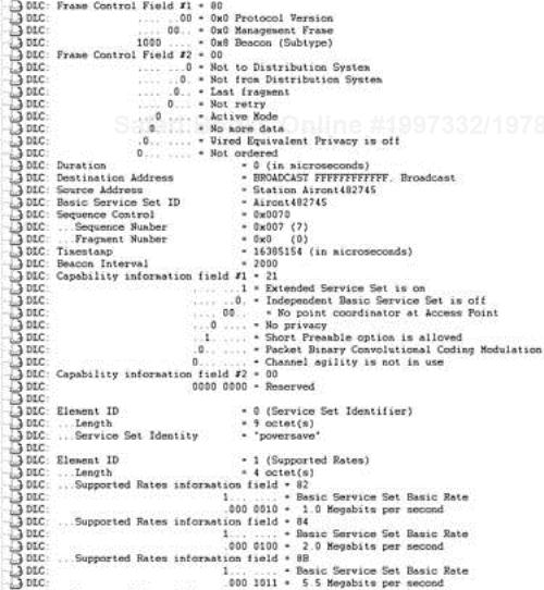
Figure 2-61 shows the frame format of a probe request frame, and Figure 2-62 shows a protocol decode of the probe request frame.


Figure 2-63 shows the frame format of a probe response frame, and Figure 2-64 shows a protocol decode of the probe response frame.
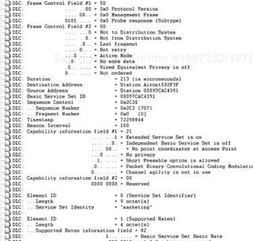
Figure 2-65 shows the frame format of an authentication frame, and Figure 2-66 shows a protocol decode of the authentication frame.


Figure 2-67 shows the frame format of a deauthentication frame, and Figure 2-68 shows a protocol decode of the Deauthentication frame.
Figure 2-69 shows the frame format of an association request frame, and Figure 2-70 shows a protocol decode of the association request frame.


Figure 2-71 shows the frame format of an association response frame, and Figure 2-72 shows a protocol decode of the association response frame.


Figure 2-73 shows the frame format of a reassociation request frame, and Figure 2-74 shows a protocol decode of the reassociation request frame.


The reassociation request frame is nearly identical to the association request frame, with the addition of the current AP address field. The key purpose of this frame is to alert the AP that the station is associating to that it had a previous association. The new AP can query the old AP for buffered frames for the roaming client, but it is a vendor-specific implementation and not defined in the 802.11 specification.
Figure 2-75 shows the frame format of a reassociation response frame, and Figure 2-76 shows a protocol decode of the reassociation response frame.

The reassociation response frame is identical to the association response frame.
Figure 2-77 shows the frame format of a disassociation frame, and Figure 2-77 shows a protocol decode of the disassociation frame.

The 802.11 specification stipulates eight unique data frames:
Data
Null data
Data+CF-Ack
Data+CF-Poll
Data+CF-Ack+CF-Poll
CF-Ack
CF-Poll
CF-Ack+CF-Poll
Figure 2-79 shows the frame format of the data frame, and Figure 2-80 shows a protocol decode of the data frame.


These data frames have the same frame body as the standard data frame. The subtype value is different to provide the CF-Ack and or CF-Poll functionality required in PCF operation.
Figure 2-81 shows the frame format of the null data frame, and Figure 2-82 shows a protocol decode of the null data frame.


A null data frame is so named because it has no payload field. Its purpose is to indicate a change in the power save mode bit in the frame control field.
The 802.11 MAC layer is more complicated than the 802.3 MAC layer, as this chapter shows. The wireless medium presents new challenges in the area of medium access, and as a result, you need a more robust MAC layer.
This chapter gave you a good understanding of basic MAC layer operations. As you progress through the book, you should be able to understand more complicated 802.11 MAC layer issues, such as MAC layer security, QoS or channel access prioritization, and mobility. These topics are covered in subsequent chapters in great detail and leverage the information contained within this chapter.