18
INTERFACING: KEYBOARDS
CHAPTER OBJECTIVES
In this chapter, the reader is introduced to keyboard interfacing, the most widely used input device for any embedded system. After completion of the chapter, the reader should be able to understand
- How does the mechanical contact-type keys function.
- What is the bouncing of keys and how to debounce those.
- How to interface individual keys as well as key-matrix with MCS-51.
- How to develop software routine to read keys and scan a keyboard.
18.1 | Introduction
Keyboard and display are two most widely used user interfaces for any embedded system. In this chapter, we discuss about some important aspects of keyboard interfacing. As a matter of fact, keys may be considered as simplest type of sensors. They are activated by finger pressure or sometimes just by touch. Table 18.1 presents the mechanism used in a few common types of keys.
Table 18.1 Some common types of keys and their mechanism
| Key type | Mechanism |
|---|---|
| Tactile keys (calculator-type keys) | Mechanical contact |
| Capacitor keys | Capacitance |
| Membrane keys | Mechanical contact |
| Hall-effect keys | Magnetic field |
18.2 | Contact Type Keys
Mechanical contact type keys are most widely used. Although inexpensive, they are less durable and may not be used in all types of environments. On the other hand, Hall-effect keys are extremely durable and may be used in any ambient conditions including underwater. However, they are of expensive variety. In this chapter, we discuss mostly about mechanical type of keys, which work by mechanical contacts. Functioning of a mechanical contact type key is shown in Fig. 18.1.
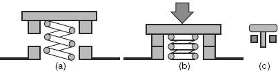
Figure 18.1 Operation of a mechanical type of key: (a) open, (b) closed and (c) symbol
18.3 | Interfacing a Key
Any mechanical key offers two states: open and closed. These mechanical states may easily be converted to corresponding electronic states using the configuration as illustrated in Fig. 18.2. Fig. 18.2(a) shows how one such key may be interfaced with an input port pin using a pull-up resistor. When the key is pressed [Fig. 18.2(b)], the mechanical contact establishes ground potential or logic ‘low’ at the input pin, through the sinking of current from the pin through the key itself. When the key is released [Fig. 18.2(c)] the input pin experiences logic ‘high’ as in this case current is sourced to the pin. To interface multiple keys, this scheme would need identical number of port pins. As an example case, we discuss the following problem.
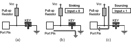
Figure 18.2 (a) Standard key interface with pull-up resistor, (b) inputting 0 and (c) inputting 1
18.4 | Solved Examples
Example 18.1
Purpose: To prepare interface for one-dimensional key array and develop proper branching routine to get access to correct entry points depending upon the key input.
Problem
Four keys to be interfaced with Port 1 of 8051 to offer four arithmetic functions: add, subtract, multiply and divide. Assuming both operands are already available in Accumulator and B-register, design the hardware and develop the software for it.
Solution
For completing the hardware part, four keys (K1, K2, K3 and K4) are interfaced with lowest four port pins of Port 1 as shown in Fig. 18.3. Function offered by each of these keys is marked just above the key. Four pull-up resistors (R1–R4) of 10K each are used in addition to internal pull-ups as shown in the circuit diagram. Note that ground connection (0V) for all keys may be common. However, each key must be having its own pull-up resistor.
Assuming that the operands are already present in the registers A and B, a software may be developed, as follows, to read keys and implement its function accordingly.
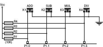
Figure 18.3 Circuit for four function input keys

When executed, the program would be in an infinite loop, which would be waiting for keys and function accordingly.
C-version
#include <regx51.h>
void main(void)
{
unsigned char operand1 = 10, operand2 = 20;
unsigned char result;
p1 = 0x00;
// infinite loop
while(1)
{
if(0 == p1_0)
{
while(0 == p1_0);
}
if(0 == p1_1)
{
result = operand1 – operand2;
while(0 == p1_1);
}
if(0 == p1_2)
{
result = operand1 * operand2;
while(0 == p1_2);
}
if(0 == p1_3)
{
result = operand1 / operand2;
while(0 == p1_3);
}
}
}
18.5 | Bouncing of Keys
When mechanical switches are pressed or released, the corresponding electrical transitions indicate some undulations just after pressing and releasing the key as illustrated in Fig. 18.4. This is known as bouncing and may be present for a maximum of 40 milliseconds.

Figure 18.4 Bouncing of mechanical contact-type keys
Bouncing effect is undesirable and generates incorrect key interpretation. Therefore, in general, any key is to be debounced before reading or accepting it as a valid input. This may be achieved by either hardware or software.
18.5.1 | Hardware Debouncing
By incorporating a capacitor and a diode, a simple circuit may be prepared for debouncing the mechanical contact type keys as shown in Fig. 18.5(a). The capacitor may or may not be electrolytic type. However, 1 μFD is a safe value for this capacitor along with a 10K pull-up resistor. The reverse biased diode is to eliminate the negative spikes, which might be generated during contacts. When pressed and released, the resulting waveform would be as shown in Fig. 18.5(b). However, one major disadvantage of hardware debouncing is the increase in overhead expenditure. On the other hand, a software debouncing routine does not add any overhead expenditure, which we would discuss now.

Figure 18.5 Hardware debouncing (a) circuit (b) signal form
18.5.2 | Software Debouncing
Software debouncing is based on the fact that the input signal oscillations, during key pressing and key releasing, do not last for more than 40 milliseconds. Therefore, whenever any key is detected, the input signal is placed under observation for more than 40 milliseconds. If the same signal is present after 40 milliseconds, then, and then only, it is taken as a valid input signal from that key. Following is an example of software debouncing.
Example 18.2
Purpose: To develop a program for software debouncing.
Problem
Modify the software developed for Example 18.1 to debounce the activated key.
Solution
For the problem of Example 18.1, software debouncing may easily be implemented by incorporating a delay routine of 50 milliseconds and calling that delay routine whenever any key is detected. If the same key is still active then it may be taken as a valid one. The modified software is presented below.


If 12 MHz crystal is used, the following routine would generate roughly 50 milliseconds delay, when called.
| DELAY: | MOV | R7, #60H |
| DELY: | MOV | R6, #00H |
| DELY1: | DJNZ | R6, DELY1 |
| DJNZ | R7, DELY | |
| RET |
We may observe in this program RDKEY that initially after sensing any key, the program calls the DELAY routine to wait for 50 milliseconds and then checks for the same key again. If the same key is still sensed then only it is taken as a valid key, otherwise not. This is one of the many ways of software debouncing.
C-version
#include <regx51.h>
void Delay50Ms (void);
void main(void)
{
unsigned char operand1 = 10, operand2 = 20;
unsigned char result;
// infinite loop
while(1)
{
if(0 == P1_0)
{
Delay50Ms();
if(0 == P1_0)
{
result = (operand1 + operand2);
while(0==P1_0);
}
}
if(0 == P1_1)
{
Delay50Ms();
if(0 == P1_1)
{
result = (operand1 – operand2);
while(0==P1_1);
}
}
if(0 == P1_2)
{
Delay50Ms();
if(0 == P1_2)
{
result = (operand1 * operand2);
while(0==P1_2);
}
}
if(0 == P1_3)
{
Delay50Ms();
if(0 == P1_3)
{
result = (operand1 / operand2);
while(0==P1_3);
}
}
}
}
void Delay50Ms(void)
{
volatile unsigned int i=6300;
while(i>0)
{
i--;
}
}
18.6 | Key Matrix
So far we have assumed that each key is sensed by one port pin. This arrangement is adoptable if number of keys are very less. However, for more number of keys, generally a two-dimensional matrix configuration is preferred. This allows us to interface more number of keys through less number of port pins, resulting in economy. As an example case, layouts of Figs 18.6(a) and (b) may be compared.
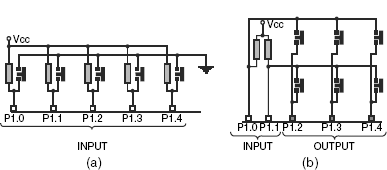
Figure 18.6 (a) 1D and (b) 2D array of keys
What would be the maximum number of keys that might be interfaced with only five port pins? In Fig. 18.6(a), using a linear arrangement, we can interface only five keys. On the other hand, as shown in Fig. 18.6(b), the two-dimensional layout would allow us to interface six keys with five port pins. It may be noted in these two cases that all port pins are in their input mode for the first configuration. In the second configuration, three are output and two are input pins. Similarly, eight port pins would allow us to interface a maximum of 16 keys in 4 × 4 matrix. The number of keys would come down to eight only, if we interface only one key for each port pin.
There is no correlation between the physical and electrical layout of keys. That is, for example, the physical layout may be only one array of ten keys, which may be electrically connected as a 2 x 5 array.
18.7 | Scanning Keyboard Matrix
The technique of reading a two-dimensional array of keys would be different from that of a linear array of keys. To explain it, we take the example of the 2 × 3 matrix, which have just been introduced. To start with, we identify three columns of this matrix driven by P1.4, P1.3 and P1.2. Two rows of this matrix are received by P1.1 and P1.0. A general algorithm for this may be as follows.
Step 1: We assign a register as key counter and clear it. We assign another register as return code and clear it too. Finally, we assign a third register as column counter and load it by 3, the number of existing columns in the matrix.
Step 2: Output 0 through one column, say P1.4, and remaining two columns should get the output as 1s as in Fig. 18.7.
Step 3: We increment the key counter by 1.
Step 4: Now read one row, say P1.0. This input would be 0 if, and only if, the key K1 is pressed. Pressing no other key at this instant (till P1.4 = 0) would produce a 0 at P1.0. If P1.0 is found to be 0, then we copy the present content of key counter in return code register. No action is taken if P1.0 = 1.
Step 5: We increment key counter by 1.
Step 6: Now we read the next row, i.e. P1.1. Just like the previous case, P1.1 would receive 0 if, and only if, K2 is pressed. Otherwise it would show 1. If P1.1 is 0, then we copy the current content of key counter in return code register.
Step 7: We decrement column counter by 1. As it is not 0, we change the input pattern so that P1.3 outputs 0 and P1.2 and P1.4 output 1s, as in Fig. 18.8.
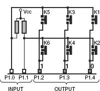
Figure 18.7 Activating first column (to read K1, K2 only)

Figure 18.8 Activating second column (to read K3, K4 only)
Step 8: We increment key counter by 1 (same as Step 3).
Step 9: We read row by P1.0, and if it is 0 then copy key counter in return code register. Note that this 0 may only be generated by pressing K3 (same as Step 4).
Step 10: Increment of key counter by 1 (same as Step 5).
Step 11: Read P1.1 and if it is 0 then copy key counter in return code register. This time it is by K4 only (same as Step 6).
Step 12: Decrement column counter by 1. As it is not 0, we change the output pattern as shown in Fig. 18.9 with P1.2 outputting 0 and remaining port pins outputting 1 (same as Step 7).
Step 13: Increment key counter by 1 (same as Step 3).
Step 14: Read P1.0 and if it is 0 (K5 pressed) then copy key counter in return code register (same as Step 4).
Step 15: Increment key counter by 1 (same as Step 5).
Step 16: Read P1.1 and if it is 0 (K6 pressed) then copy key counter in return code register (same as Step 6).
Step 17: We decrement column counter by 1. As it is 0, we terminate the routine. Observe that whichever key is pressed, its code (between 1 and 6) must be there in the return code register. If no key is pressed, return code register would be 0. If more than one key is pressed, although this is not allowed, only the last sensed key would be indicated.
Above description may be apparently a complex and longer one. However, the basic objective is to maintain only one column low at a time and keep on incrementing the key counter before testing each key input. Whenever any input is found low, the value within the key counter is to be copied immediately to the return code register. Softwarewise it is easy to implement. We will develop the complete subroutine after introducing the debouncing part within it.

Figure 18.9 Activating third and last column (to read K5 and K6 only)
In essence, we are reading every key once by assigning its column drive as 0 and reading its row input bit.
18.8 | Debouncing Keyboard Matrix
To debounce any key sensed by above algorithm, we must wait for more than 40 milliseconds to ensure it to be a valid key. Generally, it is achieved by using a debounce counter, which is loaded by the debounce value whenever any new key is detected. After scanning all keys once, this debounce counter is decremented by one and the return code is compared with the previous return code. The procedure is repeated till the debounce counter is 0. In that case the key is completely debounced. Any mismatch with previous return code would force the debounce counter to be reloaded and matching restarted. All these are explained through the following example.
Example 18.3
Purpose: To be familiar with the method of scanning and debouncing a two-dimensional array of keys.
Problem
Sixty-four keys are to be interfaced with 8051 arranged in a 8 × 8 matrix. Give a schematic of the hardware interfacing. Develop a software to generate unique key code for any key pressed. The key code must be fully debounced.
Solution
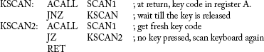
Hardware interfacing of 64 keys is schematically presented in Fig. 18.10. Port 1 was used as input port and Port 3 as output port. Eight signal lines from Port 3 (scan lines) and eight more signal lines from Port 1 (return lines) form a grid. At each intersection, only one key is accommodated so that the contact between any scan and return lines may be established by pressing the key only at their intersection. Note that if no key is pressed, there would be no connection between any scan line and any return line. For the purpose of stability, all return lines of Port 1 are externally pulled up. The software routine uses register bank #0. Usage of all related registers is explained at the starting of the software routine. This routine, KSCAN, would not return unless it can return a valid debounced key code. If at entry of KSCAN, any key is pressed, KSCAN would wait for the key to be released.
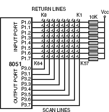
Figure 18.10 Schematic of interfacing 64 keys in 8 × 8 matrix
| ; Name: | KSCAN |
| ; Function: | Scans 64 keys arranged in 8 χ 8 matrix and returns the scan code of the active key, if any. If at |
| ; | entry of KSCAN any key is found to be pressed it would wait till the release of that key. KSCAN |
| ; | would not return until a new key is pressed. The returned scan code is fully debounced. |
| ; Input: | none |
| ; Output: | debounced key code in A |
| ; Calls: | SCAN1 |
| ; Uses: | none |
| ; Name: | SCAN1 |
| ; Function: | Scans keyboard and returns if no key pressed or with debounced key code. |
| ; Input: | None |
| ; Output: | debounced key code in A. If no key pressed then A = 0. |
| ; Calls: | DELAY |
| ; Uses: | Register bank #0 |
| ; | R1 = row counter |
| ; | R2 = debounce counter |
| ; | R3 = final key return code |
| ; | R4 = key code scanned in a cycle |
| ; | R5 = key counter |
| ; | R6 = column activating pattern (only 1 bit would be 0) |
| ; | R7 = column counter |
| ; | A = general purpose and final key code at return |
| ; | CY flag = key bit for testing |
; Initialize for a fresh key debouncing
; Initialize to scan all 64 keys.

; Activate one column, update column drive pattern and save it back. Then wait for 1 millisecond and then read ; return lines. Initialize to read returned bits.

; Read returned bits and if any bit is 0 then save key count in fresh return code counter.

; Loop for all eight columns.
| DJNZ | R7, NXTCOL | ; complete all eight columns |
; Fresh return code in R4. If both R4 and R3 are 0 then no key detected.
; Return in that case.
| MOV | A, R4 | ; fresh return code in A |
| ORL | A, R3 | ; compare with previous return code |
| JNZ | DBIT | ; some key detected, look for debounce |
| RET | ; no key pressed, accumulator = 0, return |
; Some key detected. If same key and if debouncing over then return with key code in A.

; New key. Reload debounce counter and start fresh scanning.
| ; Name: | DELAY |
| ; Function: | when called, would generate a delay of 1 millisecond. |
| ; Input: | none |
| ; Output: | none |
| ; Calls: | none |
| ; Uses: | R0 |

Note that how by calling the routine itself, the delay is doubled.
SUMMARY
Keys are most widely used input devices and are of various types such as capacitance type, membrane type and mechanical contact type. In general, they are interfaced with input ports in such a manner so that a key contact generates logic low and a key release generates logic high. Bouncing phenomena, which originates from mechanical properties of the keys, is observed during this pressing and releasing of mechanical contact type keys. They may be debounced by both hardware and software techniques, although the later one is considered to be cost effective. A matrix of keys demand lesser number of port pins for interfacing than a linear array of keys.
POINTS TO REMEMBER
- Any port pin interfaced with a key must output logic 1 to enable the port pin to read the key.
- Bouncing lasts for a maximum of 40 milliseconds and for debouncing, a key must be read for more than 40 milliseconds.
REVIEW QUESTIONS
Evaluate Yourself
- If decremented by DJNZ instruction, which of the following initial counter values would generate maximum delay?
- #0FFH
- #00H
- #60H
- None of these
- Membrane type of keys are activated through
- mechanical contact
- capacitance
- induction
- none of these
- Any mechanical contact type key can produce a maximum of
- one state
- two states
- three states
- none of these
- To input logic ‘low’ to any input pin of a port, the relevant circuit should be able to
- sink current
- produce 0V
- both of these
- none of these
- Bouncing of any mechanical contact type key may last for a maximum of
- 40 microseconds
- 4 milliseconds
- 1/4th of a second
- none of these
- For hardware debouncing, the key with pull-up resistor should be attached with
- another resistor
- a capacitor
- a diode
- none of these
- For software debouncing, it is to be ensured that the key is
- released
- sensed for more than 40 milliseconds
- sensed twice
- none of these
- The maximum number of keys may be interfaced with seven Port pins would be
- 7
- 10
- 12
- none of these
- To read any two-dimensional keyboard matrix, the output pins should output
- one 0 and others 1
- one 1 and others 0
- either of these
- none of these
- If more than one key is pressed, then the routine KSCAN would return
- first scanned key
- last scanned key
- no key
- none of these
Search for Answers
- How do the Hall-effect keys function?
- Are springs essential for mechanical contact type keys?
- What are the essential features of interfacing a mechanical contact type key with a port pin of any microcontroller?
- What is bouncing? Is it applicable for all types of keys? How can any key be debounced?
- What is the difference between hardware debouncing and software debouncing?
- What are the limitations of one-dimensional array of keys?
- What are the advantages of a two-dimensional array of keys?
- What is the methodology of scanning a two-dimensional keyboard?
- What is the role of a debounce counter in any key scanning routine?
- What would happen if the DELAY routine is not used in the routine SCAN1?
Think and Solve
- What is the difference between tactile keys and membrane type keys?
- Assuming that no internal pull-ups available, what would happen if the external pull-up resistor is removed from the interface of Fig. 18.2(a)?
- When we should interface one key per input pin, and when we should interface multiple keys per input pin?
- What would happen if all four resistors are replaced by a single resistor in Fig. 18.3?
- Under which conditions hardware debouncing would be more acceptable than software debouncing? (Hint: RESET)
- What purpose does a key counter serve in any two-dimensional key scanning routine?
- How is it possible to generate two different codes for key pressing and key releasing?
- If a 8051 microcontroller is used to read a keyboard and communicate with host computer through serial interface, what is the maximum number of keys may be interfaced in the keyboard?
- What would happen if in routine SCAN, register R6 is loaded by #80H instead of #7FH?
- Is it possible to rewrite SCAN1 routine without using R0?
(Ans.: Yes. Use A in place of R0 in delay routine.)