21
INTERFACING: DC MOTOR
CHAPTER OBJECTIVES
In this chapter, the reader is introduced to interfacing of DC motors with the 8051 microcontroller. After completion of the chapter, the reader should be able to understand
- How are DC motors interfaced with 8051 microcontroller.
- How to control speed of revolution of a DC motor using 8051.
- How to control the direction of rotation of a DC motor using 8051.
- How to interface relay and optocoupler for interfacing heavy-duty DC motors.
21.1 | Introduction
Motors are of various types out of which DC motor, Stepper motor and Servomotors are more widely used for different digital-control operations. In this and next two chapters, we will discuss about different interfacing issues related to these motors.
21.1.1 | How DC Motor Works
To recapitulate some fundamental concepts, let us have a quick discussion on the working principle of DC motors. Fleming’s left-hand rule is an easier way to remember it. Incidentally, Fleming’s right-hand rule is for generators (riGht and Generator both have a ‘G’: the easier way to remember). As shown in Fig. 21.1, the forefinger indicates the direction of magnetic field (from north to south), the middle finger indicates the direction of current flow and the thumb indicates the direction of force experienced, when current is allowed to pass through a conductor placed perpendicular to any magnetic field.
This force is doubled if the single wire is replaced by a loop as shown in Fig. 21.2. To supply current with proper direction, even during circular rotations, brushes and split-ring commutator are used at the free end of the loop (not shown in Fig. 21.2). In standard DC motors, the number of loops are not one but many, wound around the armature, which increase the torque. Moreover, instead of permanent magnets, electromagnets are used. However, the principle of converting electrical energy to mechanical energy remains unchanged. The rotating part of the motor is designated as rotor and the outer static part is known as stator. DC motors may also be of a brush-less variety known as brush-less DC motor (BLDM). Two controllable parameters of rotation of any DC motor are its speed and direction. We will now discuss about both of these issues.

Figure 21.1 Fleming’s left-hand rule for motors

Figure 21.2 How DC motor works
21.2 | Direction Control
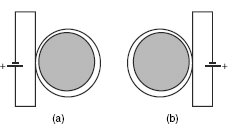
Fleming’s left-hand rule indicates that the change of direction of current changes the direction of motion. As indicated in Fig. 21.3, the direction of rotation of a DC motor may be reversed by interchanging its input voltage polarity, which reverses the direction of current flow. If we assume that initially it is rotating in clockwise direction [Fig. 21.3(a)], then it would start rotating in anticlockwise direction by the reversed polarity [Fig. 21.3(b)]. When this is to be done manually, a DPDT switch may be used. However, the general practice is to use the H-bridge configuration for interchanging the polarity.
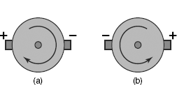
Figure 21.3 Direction changing through polarity interchange: (a) clockwise and (b) anticlockwise
21.2.1 | H-Bridge
Fig. 21.4 shows the schematic of an H-bridge. Note that the supply (Vcc) and ground (GND) are available to both pins (inputs) of the motor through four SPST switches. If S1 and S2 are closed and S3 and S4 are open, then the current from Vcc would travel through motor from left to right generating, say, clockwise motion. On the other hand, if S1 and S2 are open and S3 and S4 are closed then the previous input polarity gets interchanged and the current flows from right to left through the motor, generating anticlockwise rotation. It would be interesting for the reader to find out what would happen ifS1 and S4 are simultaneously closed. In practice, these switches are replaced by transistors, which may be controlled electronically. This is discussed in the next section.
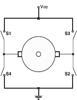
Figure 21.4 Polarity interchanging using H-bridge
21.2.2 | H-Bridge Using Transistors
As shown in Fig. 21.5, four switches of the H-bridge of Fig. 21.4 were replaced by four transistors. Two PNP transistors, TIP127 were used to source the current and two NPN transistors, TIP122 were used to sink the current. Just like the previous case, at any time only two transistors should be on (working) and remaining two should be off. It may be noted that NPN transistors are turned on by logic 1 applied at the base and PNP transistors are turned on by logic 0. Table 21.1 gives the input details of rotation control through these transistors.

Figure 21.5 H-bridge using transistors
Table 21.1 Direction control through transistors

In Fig. 21.5, it is indicated that bases of all four transistors are activated by ports of 8051. However, the output from port pins of 8051 may not be strong enough to drive these bases directly and might have to be boosted with another small transistor, like BC547.
21.2.3 | L293D
Dedicated integrated circuits (ICs) are available for driving different types of motors. L293D is one of such ICs, whose pin diagram is shown in Fig. 21.6. It contains four non-inverting drivers placed as two pairs. Each pair may individually be enabled or disabled through its ENABLE input. Each driver is capable of sourcing or sinking 600 milliamperes of current with a peak value of 1.2 amperes. Vs (pin 8) is for motor power supply voltage input, with a minimum limit of 5 V and a maximum of 36 V. Vss (pin 16) is for logic level input voltage with a minimum rating of 5 V.
To drive a DC motor, only one pair of drivers is necessary, which (OUTPUT from L293D) may be connected with poles of the motor directly. Signals marked as INPUT may be driven by port pins of any microcontroller. As there is no heat sink provision, the ground plane in PCB layout to be carefully planned (refer to manufacturer’s data sheet).

Figure 21.6 Pin diagram of L293D
Apart from L293D, there are quite a few H-bridge drivers available in the market. Some of them are: L287M, 2295, etc. Interested reader may search in the internet for further details.
21.3 | Speed Control
Speed of rotation of any DC motor may be controlled either by changing its input current or by input voltage. A schematic to implement this may be a variable resistance connected in series with the motor as shown in Fig. 21.7. Note that such a scheme changes both input voltage and input current simultaneously.
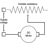
Figure 21.7 Schematic of speed control by varying input voltage/current
21.3.1 | Through DAC
Digital to Analog Converters (DACs) may also be used to control the input voltage of a DC motor. The technique to change the output voltage of any DAC had been discussed in Chapter 20.
21.3.2 | Changing Duty Cycle of Square Wave
Pulse-Width Modulation or PWM is another widely adopted technique to control the input voltage (and, therefore, the speed) of a DC motor. As shown in Fig. 21.8, variation of duty cycle of a square wave changes the value of average output voltage, and the inertial force of the motor keeps it rotating during the off stage of the square wave. Increasing the duty cycle increases the speed of rotation and vice versa. In this case, ‘duty cycle’ means the on-time with respect to the time taken by one complete on-off cycle.
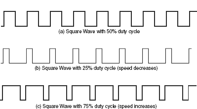
Figure 21.8 Speed control through duty cycle
21.4 | Relay and Optocoupler
Whatever we have discussed so far was related to small-sized DC motor interfacing. However, to control larger DC motors, which needs larger amount of voltage and current or to operate AC, the normal transistors or L293D would not be suitable. In such conditions we should use a relay. A relay is nothing but an electronic switch, which turns on or off very high voltage, high current devices, driven by digital level signals. In early days, they used to contain mechanical moving parts. However, nowadays Solid State Relay (SSR) is available to replace them.
Fig. 21.9(a) illustrates the schematic of a SSR. Note the built-in optocoupler (also known as optoisolator) at its right side. This optocoupler is necessary to protect the digital circuit from high-voltage transients produced during operation of the relay. We can prepare our own optocoupler by using a LED and a LDR. At the left side of the schematic, we find two MOSFETs connected back to back. Although a single MOSFET is sufficient to handle DC; however, for AC operations two MOSFETs are necessary. Source pins of these two MOSFETs are tied together.
Fig. 21.9(b) shows the application interface, necessary to drive an AC load (a motor or a ceiling fan) by 8051 through a SSR. To activate the relay, the port pin is to output logic 0.
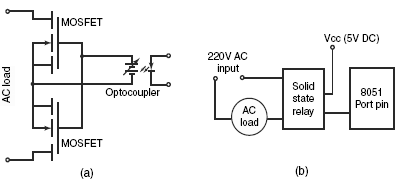
Figure 21.9 (a) Schematic of a SSR with built-in optocoupler and (b) interfacing with 8051 control AC load
As relays are generally driven by 220V AC, therefore, special precaution must be taken to interface a relay with any 8051 based circuit, which is generally powered by 5V DC. It is preferable for a beginner not to attempt any circuit fabrication incorporating a relay. Some experience is essential to construct such an interfacing.
21.5 | Solved Examples
Example 21.1
Purpose: To understand about hardware interfacing and direction control through software for a DC motor.
Problem
Prepare a suitable hardware interface for a DC motor and develop a software routine to change its direction of rotation.
Solution
Using two port pins of 8051, P1.0 and P1.1, a hardware interface for a 12 V DC motor through L293D is presented in Fig. 21.10. To use another DC motor of some other voltage, say 9 V, the Vs input (pin 8) of L293D is to be changed to 9 V DC. Note the presence of a pair of pull-up resistors of 10K each at the Port 1 output. Half of the L293D was disabled by grounding its ENABLE 2 input. Furthermore, its unused input pins 10 and 15 are also connected with system ground. The output through two port pins must be complementary to run the motor. That is, if P1.0 is high, then P1.1 must be low and vice versa. A software routine (DCDIR) to run the DC motor in one direction for about a second and then reversing its direction of rotation for another second is given below. Note that the program is an infinite loop.
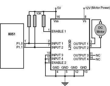
Figure 21.10 Interfacing L293D with 8051 for direction control
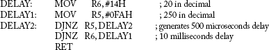
; Direction control of a DC motor
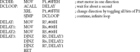
To increase or decrease the run time for either direction, the immediate value loaded in R7 in routine DELAY may be adjusted accordingly. Note the usage of XRL instruction to change the direction.
C-version
#include <regx51.h>
void Delay1Sec(void);
void main(void)
{
P1 = 0xFE;
// infinite loop
while(1)
{
Delay1Sec();
P1 ˄= 0xFF;
}
}
void Delay1Sec(void)
{
volatile unsigned long i=12000;
while(i>0)
{
i--;
}
}
Example 21.2
Purpose: To understand how the speed of a DC motor may be controlled through software using PWM.
Problem
Develop a subroutine to run a DC motor interfaced with 8051 at alternately faster and slower speeds.
Solution
Assuming the same hardware interface as shown in Fig. 21.10, the speed may be controlled by changing the duty cycle of a square wave output from P1. We interchange the duty cycle between 75 per cent and 25 per cent as shown in Fig. 21.11, the duration of each being ~1 second.
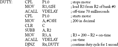
; Speed control of a DC motor by PWM

Note that the motor is started with higher speed to overcome the initial inertia. If the motor does not turn, count value (14H) in R5 of DELAY may be suitably increased. For 75 per cent duty cycle, DELAY is called thrice during on-time while for 25 per cent duty cycle, DELAY is called only once during on-time. The proportion of on-time and off-time fixes the duty cycle.

Figure 21.11 PWM waveform for speed changing
A saw-tooth wave form from any DAC may also be used to generate the same effect of the motor speed variations.
Example 21.3
Purpose: To understand how the acceleration of a DC motor may be controlled through software using PWM.
Problem
Develop a routine so that a DC motor accelerates after starting.
Solution
To accelerate a DC motor, its duty cycle to be increased in uniform steps. A schematic representation of the waveform is shown in Fig. 21.12. To implement a noticeable acceleration, duration of each step may be maintained for about a second. The duty cycle may be increased from 30 per cent to 90 per cent in steps of 10 per cent. As indicated in Fig. 21.12, there should be a starting pulse (on-time) of 50 milliseconds duration to overcome the initial inertia. The software is presented below with the same hardware as shown in Fig. 21.10.

Figure 21.12 Waveform to implement acceleration
; Acceleration control of a DC motor
; Use register bank #0
; R1 = counter for seven steps from 30% to 90% duty cycle
; R2 = controls delay count starting from 140 and decremented at steps of 20.
; R3 = variable delay count. To be loaded direct from R2 or 200–R2
; R4 = counts 10 cycles of 100 milliseconds each
; R5 = inner delay counter (250–0)
; R6 = outer delay counter, loaded from R3 before start of delay counting
; Following three instructions generates 50 milliseconds on-time to overcome initial inertia.
; Following two instructions initializes for seven steps of increment duty cycle.
| MOV | R2, #8CH | ; 140 in decimal for 70 milliseconds delay |
| MOV | R1, #07H | ; seven steps from 30% to 90% duty cycle |
; Loop for incrementing duty cycle starts from here. Each time the loop passes through this point, the speed
; is incremented by 10%.
; Start of one cycle of off-time followed by on-time.
; Process R2 by subtracting 20 from it for next duty cycle.
| MOV | A, R2 | ; decrease off-time duration for next phase |
| CLR | C | |
| SUBB | A, #14H | ; 20d |
| MOV | R2, A | ; R2 = R2 – 20d |
| DJNZ | R1, ACCNXT | ; next step of acceleration |
| RET | ; motor runs at full speed |
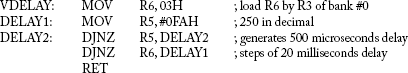
; Variable time delay routine. Variable input from R3 of bank #0.
A sine wave form generated by any DAC is also capable of producing acceleration for any DC motor.
SUMMARY
Two major controlling parameters of DC motors, namely, direction control and speed control may be achieved by interfacing through transistor-controlled H-bridge or ICs like L293D. Interchanging the input polarity of any DC motor reverses its direction of rotation. Input voltage change by varying the duty cycle of a square wave, known as PWM, is a widely used technique to control the speed of any DC motor.
POINTS TO REMEMBER
- If a DAC is used to drive a DC motor, then the current requirement of the DC motor and the output current limit of the DAC must be checked.
- Larger pulse width is necessary at start to overcome the initial inertia of any DC motor if it is driven by PWM.
REVIEW QUESTIONS
Evaluate Yourself
- In Fleming’s left-hand rule, the middle finger indicates the direction of
- magnetic field
- motion
- current flow
- none of these
- ‘Fleming’s right-hand rule is for
- generator
- AC motor
- armature winding
- none of these
- The magnetic field is always directed as
- from North to South
- from South to North
- either of these
- none of these
- To reverse the direction of rotation of any DC motor, we have to
- To make any H-bridge operational (refer to Fig. 21.4), how many switches must remain closed at the same time?
- One
- Two
- Three
- None of these
- If logic 0 is applied at the base of any PNP transistor, it would be
- tri-stated
- turned off
- turned on
- none of these
- Using only one L293D, what is the maximum number of DC motors that could be controlled for direction of rotation?
- One
- Two
- Three
- None of these
- The duty cycle of any square wave signal is its
- time period
- on-time
- off-time
- none of these
- The Vs input of L293D should have the voltage for
- motor drive
- logic level
- double of motor drive
- none of these
- If the duty cycle of a square wave to drive a DC motor is changed from 30 per cent to 50 per cent, the speed of the motor would
- increase
- decrease
- remain constant
- none of these
Search for Answers
- What is Fleming’s left-hand rule?
- What is meant by stator and rotor?
- What is known as BLDM?
- In how many ways the speed of any DC motor may be controlled?
- What are the advantages of PWM over other methods?
- How the present direction of rotation of a DC motor may be reversed?
- What is an H-bridge? Where are they used for?
- What purpose does L293D serve?
- What are input voltage ranges of L293D?
- How transistors may be used to drive DC motors and control its direction?
Think and Solve
- What magnetic polarities the following coils windings [Figs 21.13(a) and (b)] would be generating?
- What is the role of a ‘delay’ routine in direction control and speed control of any DC motor?
- Calculate the duty cycle if the on-time is 10 milliseconds and off-time is 90 milliseconds. How would it vary if off-time is decreased to 1 millisecond, while the on-time remains unchanged?
- Draw the timing diagram of signals from both P1.0 and P1.1, covering direction change of the DC motor. Start the diagram assuming any direction.
- What is the minimum voltage of any DC motor that may be controlled by L293D?
- Can only one L293D be capable of controlling four DC motors? Here the controlling is only in terms of starting and stopping.
- What are the advantages and disadvantages of L239D over a H-bridge prepared from transistors?
- Assuming that port 1.2 and 1.3 are connected with two keys, K1 and K2, respectively, and all other interfacing of Fig. 21.9 remaining same, develop a program to start the motor when K1 is pressed and stop it when K2 is pressed.
- Develop a routine to decrease the speed of a DC motor in several steps and finally stop it. Assume that the same L293D interfacing as shown in Fig. 21.9 is used.
- Modify the circuit of Fig. 21.9, so that it can control two DC motors. Use additional port pins P1.6 and P1.7 for it.