INTRODUCTION
This book will help you improve your electronics skills. I’ll teach you how to interpret circuit diagrams and use breadboards. Then I’ll show you, step-by-step, how to build a simple circuit on a breadboard. After that, you’re on your own: you’ll rely on parts lists and circuit diagrams to build your circuits. Building circuits from diagrams is an essential skill for anyone interested in electronics, from beginners to experts.
THE CIRCUITS
The circuits become more and more difficult to build as you progress through the book. Here’s a brief description of each circuit project:
- Project 1: The Steady-Hand Game With this super-simple circuit, you’ll create an Operation-style game where you need a steady hand to win.
- Project 2: The Touch-Enabled Light Using a touchpad, you’ll build a touch-enabled light switch to turn on a light with your finger.
- Project 3: The Cookie Jar Alarm Keep your cookies safe with this cookie jar alarm, which will scare any cookie thieves away with a buzzing noise.
- Project 4: The Night-Light Here you’ll build a light that turns on in the dark to help you see things at night.
- Project 5: The Blinking LED In this project, you’ll learn some of the basics of digital electronics and use an integrated circuit to blink an LED.
- Project 6: The Railroad Crossing Light Add to your model train set with the railroad crossing light, a classic circuit that everyone should build at some point.
- Project 7: The Party Lights This string of blinking lights is a perfect project to prepare for an upcoming party.
- Project 8: The Digital Piano Build your own musical instrument from scratch and entertain your friends and family!
- Project 9: The LED Marquee In this final circuit, you’ll use your new skills to create an awesome LED light show.
You can find resources for the circuits through the book’s website at https://nostarch.com/circuits/.
THE MATERIALS
All of the materials you’ll need to build the circuits in this book are inexpensive and easy to find. Here’s a list of all the electronic components you’ll need.
NOTE
The part numbers shown here are for Jameco Electronics (https://www.jameco.com/). These components should be available from any electronics supply store.
# |
JAMECO PART NUMBER |
VALUE |
DESCRIPTION |
1 |
#198731 |
9 V battery |
Standard 9 V battery |
1 |
#109154 |
Battery clip |
Component that connects the battery to the breadboard |
1 |
#20601 |
Breadboard |
Breadboard with around 400 holes |
20 |
#2237044 |
Jumper wires |
Pack of at least 20 breadboard jumper wires |
1 |
Included in #2217511 |
100 Ω |
Standard resistor |
4 |
Included in #2217511 |
1 kΩ |
Standard resistors |
2 |
Included in #2217511 |
10 kΩ |
Standard resistors |
1 |
Included in #2217511 |
100 kΩ |
Standard resistor |
2 |
Included in #2217511 |
470 Ω |
Standard resistors |
2 |
Included in #2217511 |
47 kΩ |
Standard resistors |
1 |
#151116 |
0.1 μF |
Nonpolarized capacitor |
1 |
#31000 |
4.7 μF |
Polarized capacitor |
2 |
#94212 |
10 μF |
Polarized capacitors |
1 |
#158394 |
100 μF |
Polarized capacitor |
2 |
#254801 |
BC547 |
Any general-purpose NPN transistor will work |
10 |
#333973 |
LED |
Standard light-emitting diodes; all must have about the same forward voltage (Vf) |
1 |
#904085 |
NE555 |
555 timer IC |
1 |
#12749 |
CD4017B |
4017 decade counter IC |
1 |
#44257 |
74C14 |
Hex Schmitt trigger inverter |
4 |
#119011 |
Momentary ON |
Tactile mini-pushbuttons |
1 |
#202454 |
LDR/photoresistor |
Light-dependent resistor (photoresistor) with around 5 to 10 kΩ resistance in light and 200 kΩ or more in dark |
1 |
#2239146 |
8 Ω speaker |
Mini-speaker |
1 |
#2120452 |
Buzzer |
Active buzzer that works with a 9 V battery |
With your materials in hand, let’s get started!
HOW TO BUILD THE CIRCUITS IN THIS BOOK
For each circuit in this book, I provide a circuit diagram and a parts list. Circuit diagrams are drawings that show you how to connect components to build an electronic circuit (see Figure 1).

FIGURE 1 This circuit diagram shows you how to connect a battery, a resistor, and an LED.
The parts list tells you which component values you should use—for example, a resistor with a value of 470 Ω or a capacitor with a value of 10 μF. Each component has a symbol, and these symbols are connected with lines that show you how to connect the components. With a little practice with circuit diagrams, you’ll quickly learn how to distinguish the different symbols.
What the Components Look Like
In this section, I’ve listed each component next to the symbol used for it in this book. You might see different symbols for the same component in other electronics books or resources, but in this book, they will be consistent.
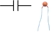
Battery

Resistor

Capacitor, nonpolarized
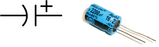
Capacitor, polarized
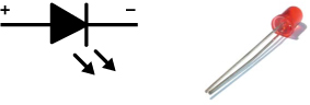
Light-emitting diode (LED)
Light-dependent resistor (LDR)

Transistor

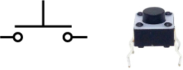
Pushbutton (switch)
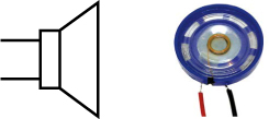
Speaker
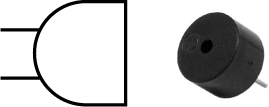
Buzzer
Integrated circuit
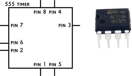
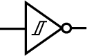
Note that some integrated circuits, such as the following Schmitt trigger inverter, use a symbol that represents their function instead of the box symbol.
Building Circuits on a Breadboard
A breadboard is a really simple tool for building a circuit. Because you don’t have to solder—you just plug in the components—you can easily reuse components if you want to build something else later.
Most breadboards have two areas for components and two areas for power supplies. I’ve labeled these four areas in Figure 2. The five holes of each row in a component area—labeled with a numeral—are connected by metal strips inside the board. The rows in the left component area are not connected to the rows in the right component area.

FIGURE 2 A typical breadboard with labeled areas
The wires of a component are called its pins, legs, or leads. To make a connection between two components, you plug their pins into the same row in one of the component areas. If you can’t connect them on the same row, you can use a jumper wire in order to make the connection from one row to another.
In Figure 3, the lower pin of the resistor and the upper pin of the LED are connected to each other on row 7. The upper pin of the resistor and the lower pin of the LED don’t share a row with any component, so they aren’t connected to anything.

FIGURE 3 Connecting a resistor and an LED
The holes in the supply areas are connected column-wise instead. So if you connect the positive (or plus) terminal of your battery to the top-left hole of the left-hand supply area, all the holes from the top of that column to the bottom will be connected to the positive terminal of your battery.
NOTE
On bigger breadboards, the supply areas are sometimes divided into four areas: top right, top left, bottom right, and bottom left.