7
THE PARTY LIGHTS
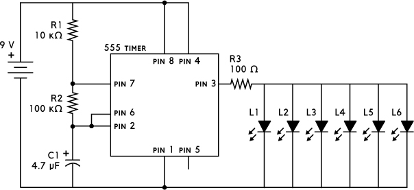
THIS CIRCUIT CONNECTS MULTIPLE BLINKING LEDS TO MAKE STRING LIGHTS.

THE CIRCUIT DIAGRAM
THE PARTS LIST
PART |
VALUE |
DESCRIPTION |
R1 |
10 kΩ |
Standard resistor |
R2 |
100 kΩ |
Standard resistor |
R3 |
100 Ω |
Standard resistor |
C1 |
4.7 μF |
Polarized capacitor |
L1 to L6 |
Red, yellow, or green |
Standard LEDs; all must have about the same forward voltage (Vf) |
U1 |
NE555 |
555 timer IC |
ABOUT THE CIRCUIT
If you want to make something cool for a party, this is the circuit for you. It’s a simple way to make several LEDs blink at the same time. By roping all the lights together on a single long wire, you can hang them in a window or use them to decorate a tree.
The circuit uses a 555 timer, which is a classic integrated circuit that makes things turn on and off repeatedly; you can see the timer’s pinout in Figure 7-1.
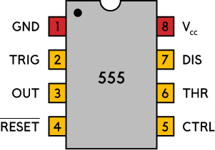
FIGURE 7-1 555 timer pinout
Two resistors (R1 and R2) and a polarized capacitor (C1) set the blinking speed, while a third resistor (R3) determines the current that goes out to the LEDs.
COMMON MISTAKES
If your circuit isn’t working correctly, you might have made one of these common mistakes:
- Connecting one or more of the LEDs the wrong way
- Connecting the 555 timer the wrong way
- Connecting the capacitor the wrong way around
- Mixing up the pin numbers of the IC and connecting components to the wrong pin
You can add or remove LEDs by changing the value of the resistor (R3). If each LED needs 10 mA and you want to use five LEDs, you need 5 × 10 mA, or 50 mA, through the resistor. You can use Ohm’s law to figure out the correct resistor value:
Ohm’s law states that the resistance is equal to the voltage across the resistor divided by the current flowing through it. In your five-LED example, that translates to the following equation:
In this case, you are working with a 9 V battery and there’s about 2 V across the LEDs, so you get 7 V as the numerator. You divide that by the 50 mA calculated earlier to get 140 Ω of resistance. Note that your circuit will require less resistance as you add more LEDs and more resistance as you remove LEDs.
If you’re struggling with this circuit, you can ask questions and make comments through the book’s website at https://nostarch.com/circuits/.
NOTE
A 555 timer can give out only 100 to 200 mA in total. Check your chip’s datasheet for the exact value.
HOW THE CIRCUIT WORKS
Figure 7-2 shows the inside of the 555 timer. The green box marked “flip-flop” is a simple memory device with two states: output high (flip) and output low (flop). It has two inputs, set (S) and reset (R), which either set the output (Q) to high or reset it to low. Q is always the opposite of ![]() .
.
The two triangles you see are comparators. If the comparator input marked with + has a higher voltage than the one marked with –, the output is high; otherwise, the output is low.
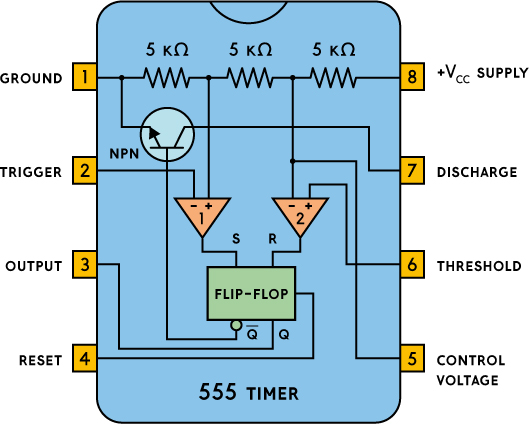
FIGURE 7-2 The inside of a 555 timer
The three 5 kΩ resistors between VCC and Gnd are the reason for the name “555.” They divide the VCC voltage by three and set fixed voltages for each of the comparators: one-third of the VCC voltage goes to the positive (+) input of comparator 1, and two-thirds of the VCC voltage goes to the negative (–) input of comparator 2.
If you look at the output (pin 3) in Figure 7-2, you’ll see that it’s connected to the output of the flip-flop. This means that if the flip-flop is “set,” the output is high; otherwise, it is low. If you look at the input to the flip-flop, you’ll see that the two comparators handle setting and resetting the flip-flop. This means that the pins responsible for making the output turn on and off are pins 2 and 6.
Pin 2 is labeled Trigger and is responsible for setting the output high. When the voltage on pin 2 goes lower than one-third of VCC, comparator 1 outputs high and sets the flip-flop, which in turn sets the output high. Pin 6 is labeled Threshold; when its voltage exceeds two-thirds of the VCC, it is responsible for resetting the output to low.
Refer back to the circuit diagram at the beginning of this project. For this project’s circuit, pins 2 and 6 are connected to each other, so when the voltage on these pins goes high, the output goes low. When the voltage on these pins goes low, the output goes high. That means you need to switch the voltage on these pins between high and low in order to switch the output between low and high.
Pin 7 is very important for making this happen. It is labeled Discharge. Inside the chip, pin 7 is connected to a transistor, as shown in the figure. The transistor is controlled by ![]() , the opposite value of the output. This means that when the output is low, the transistor gets a high value and turns on, connecting pin 7 to ground. Otherwise, the transistor is off and leaves pin 7 unconnected.
, the opposite value of the output. This means that when the output is low, the transistor gets a high value and turns on, connecting pin 7 to ground. Otherwise, the transistor is off and leaves pin 7 unconnected.
The moment we apply power to our circuit, capacitor C1 is completely discharged. That means pin 2 (Trigger) is low, which means pin 3 (the output) is high. This also means that pin 7 (Discharge) is not connected to anything internally.
Since C1 is connected to 9 V through R1 and R2, C1 will start to charge, and the voltage on its positive pin will begin to rise. This means the voltage on pin 6 (Threshold) is increasing, too. When the voltage becomes high enough on Threshold, the output changes from high to low, and pin 7 (Discharge) is connected internally to ground.
In this situation, when pin 7 is connected to ground, the capacitor will start to discharge (hence the pin name Discharge) through R2, down to ground at pin 7. So the voltage across the capacitor decreases and continues to do so until the voltage on pin 2 is so low that it “triggers.” When it triggers, the output switches from low to high, and pin 7 is disconnected from ground again.
Now we’re in the same situation as when we started, where the capacitor is charging so that the voltage over the capacitor increases. This process repeats indefinitely.
The following is a brief overview of each pin on the 555 timer:
- Pin 1 Ground This pin is connected to the negative side of the battery.
- Pin 2 Trigger When this pin goes low (less than one-third of VCC), the output goes high.
- Pin 3 Output The output voltage from the chip is around 1.5 V lower than VCC when high and around 0 V when low.
- Pin 4 Reset This pin resets the whole circuit. It’s an “inverted” pin, which means it resets when the pin goes low. This means the pin must be high normally so that the chip isn’t in a “reset” state.
- Pin 5 Control Voltage This pin is used to control the threshold voltage of the Threshold pin. This can be useful when you want to adjust the frequency of the circuit without changing the values of R1, R2, and C1. For this circuit, you can leave it unconnected. Sometimes you’ll see this pin connected with a capacitor to ground; this is a way to keep any noise on it from influencing the frequency.
- Pin 6 Threshold This pin sets the output back to low when the voltage goes high (above two-thirds of VCC).
- Pin 7 Discharge This pin is unconnected when output is high, and it’s connected to ground when output is low.
- Pin 8 VCC Supply This is the positive power supply pin and can take a voltage between 5 and 15 V.