8
THE DIGITAL PIANO
THIS PROJECT’S FOUR BUTTONS PLAY FOUR UNIQUE TONES.

THE CIRCUIT DIAGRAM

THE PARTS LIST
PART |
VALUE |
DESCRIPTION |
R1 |
1 kΩ |
Standard resistor |
R2 |
10 kΩ |
Standard resistor |
R3–5 |
1 kΩ |
Three standard resistors |
R6 |
100 Ω |
Standard resistor |
C1 |
0.1 μF |
Nonpolarized capacitor |
U1 |
NE555 |
555 timer IC |
S1–S4 |
Momentary ON |
Four tactile mini-pushbuttons |
SPK1 |
8 Ω |
Mini-speaker |
ABOUT THE CIRCUIT
In this circuit, you’ll build a musical instrument with four buttons that play four different tones.
To create sound, you need to send an oscillating voltage to the speaker. So, you’ll use a 555 timer to create a voltage that goes on and off rapidly—meaning a few hundred times per second!
The value of capacitor C1, the value of resistor R5, and the resistance between pins 6 and 7 will set the tone of the sound. You’ll place resistors between each pushbutton, so pressing a button affects the circuit’s resistance. That means the resistance between pins 6 and 7 will differ depending on which button you push, resulting in a different tone for each.
A pushbutton has four pins. When you look at it from the point of view shown in Figure 8-1, the two pins in front are always connected to each other. The same is true for the two pins in the back. When you push the button, the front pair gets connected to the back pair.

FIGURE 8-1 A pushbutton has four pins.
My preferred way to connect the pushbuttons for this project is across the gap in the middle of the board, as shown in Figure 8-2. This gives you plenty of room to connect the resistors and necessary wires. Don’t worry about the rotation, as the pushbuttons will only fit one way.
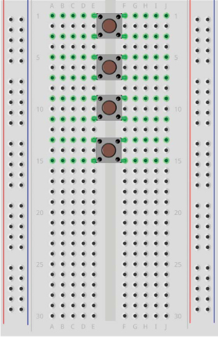
FIGURE 8-2 Connect the pushbuttons so they span the gap.
It’s a good idea to build the circuit with just one button first. Start by connecting button S1. Then add the three other buttons once you’ve gotten the first one working.
WARNING
Make sure the resistor R6 is in series with the speaker for two reasons: (1) to limit the current to the speaker so that even very small speakers don’t break and (2) to make sure you don’t destroy the IC by squeezing out more current than it can handle.
COMMON MISTAKES
If you’re having trouble getting the circuit to work correctly, check that you haven’t made one of these common mistakes:
- Connecting the 555 timer the wrong way
- Mixing up the pin numbers of the IC and connecting components to the wrong pin
- Forgetting to connect a wire (With so many connections, it’s easy to lose track!)
If you want more than four buttons on your keyboard, you can add more pushbuttons and resistors.
If you’re struggling with this circuit, you can ask questions and make comments through the book’s website at https://nostarch.com/circuits/.
HOW THE CIRCUIT WORKS
In the previous chapter, you learned how the 555 timer works. This circuit works in the same way, except that in Project 7 the output turned on and off slowly, maybe one time per second. In this circuit, the output switches on and off several hundred times per second!
The capacitor C1 and the resistors R1 to R5 determine how frequently the output (pin 3) switches between a high and a low voltage. To calculate the exact frequency of the sound you hear, you’ll use the formula for the switching frequency of a 555 timer:

The RX value is the resistance between pins 6 and 7, so it will depend on which button you push. Let’s see what frequency you get when you push S1:

If you enter these values into a calculator, you’ll get 686. That means the frequency for the first button is 686 Hz.
For the other buttons, here is the value for RX that you need to enter into the frequency formula:

If you crunch these numbers on a calculator, you should get:
S2: 626 Hz
S3: 576 Hz
S4: 533 Hz
If you want to change the frequency (or tone) of each button, you need to change the value of resistors R2 to R5. Try changing in increments of 100 Ω first, and then in smaller and smaller increments to fine-tune the tone. Connecting two resistors in series gives you a total resistance equaling their sum.