
3
THE COOKIE JAR ALARM
THIS ALARM BUZZES WHEN IT SENSES LIGHT.

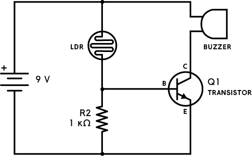
THE CIRCUIT DIAGRAM
THE PARTS LIST
PART |
VALUE |
DESCRIPTION |
LDR |
200 kΩ |
Light-dependent resistor (photoresistor) with around 5 to 10 kΩ resistance in light and 200 kΩ or more in dark |
Q1 |
BC547 |
Any general-purpose NPN transistor |
R2 |
1 kΩ |
Standard resistor |
Buzzer |
|
Active buzzer that works with a 9 V battery |
ABOUT THE CIRCUIT
Do you want to keep people from stealing cookies from your cookie jar? Or keep spies from snooping in your treasure chest? Then this circuit is for you.
This circuit stays quiet when it’s in a dark place, such as in a cookie jar with the lid on. But once the lid comes off and lets light inside, the circuit sounds an alarm that should scare off any cookie thieves.
The circuit uses a light-dependent resistor (LDR) to detect light. Its resistance changes when it detects more or less light. The more light the LDR detects, the lower the resistance.
The LDR and R2 make up a voltage divider, which controls the amount of input voltage at the base of the transistor, switching the transistor off or on depending on how much light is detected.
Once your circuit is complete, you can put it in your cookie jar or treasure chest to protect your precious belongings.
COMMON MISTAKES
If you can’t get the circuit to work, check for the following:
- The resistance value of R2 is too high or too low. Refer to “Resistor Color Codes” on page 64 for help reading the resistor’s color coding.
- You connected the transistor the wrong way. If you need a refresher on connecting an NPN transistor, refer to Project 2.
If you want to make the circuit more or less sensitive to light, replace R2 with a higher (more sensitive) or lower (less sensitive) resistance value.
If you have questions about this circuit, you can find more resources through the book’s website at https://nostarch.com/circuits/.
HOW THE CIRCUIT WORKS
The buzzer will sound only if current is flowing through it, which can happen only if there is a path from the battery’s positive terminal to its negative terminal. This means the alarm will sound only if the transistor is turned “on” so that current can flow from the battery’s positive terminal through the buzzer, then from the transistor’s collector to its emitter, and finally back into the battery’s negative terminal.
As you saw in Project 2, for a transistor to be turned “on,” current needs to flow from its base to its emitter. This happens only when the voltage between the base and emitter is about 0.7 V. When the voltage is much less than 0.7 V, no current flows through the base, and emitter and the transistor is off.
In the circuit diagram in Figure 3-1, you can see that the voltage from the base to the emitter is equivalent to the voltage across R2.
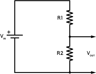
FIGURE 3-1 Creating a voltage divider
The LDR and R2 are connected to form a voltage divider. The LDR is R1 in this diagram. The formula for calculating the output voltage from a voltage divider is:
If it’s dark, the LDR has around 200 kΩ resistance or more, and R2 is always 1 kΩ. You’re using a 9 V battery, so Vin is 9 V. If you plug these values into the formula, you get:
This gives you a Vout of about 0.04 V, which is too low for the transistor to turn on.
If it’s light, the LDR has around 10 kΩ resistance or less. Plug this into the voltage divider formula, and you’ll get:

In this case, Vout equals about 0.8 V. This is more than the 0.7 V required for current to flow from the base to the emitter, so the transistor turns “on,” allowing current to flow through the buzzer, collector, and emitter and sounding the alarm.