6
THE RAILROAD CROSSING LIGHT
THIS CIRCUIT FLASHES TWO LEDS IN AN ALTERNATING PATTERN.

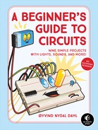
THE CIRCUIT DIAGRAM
THE PARTS LIST
PART |
VALUE |
DESCRIPTION |
R1, R4 |
470 Ω |
Standard resistor |
R2, R3 |
47 kΩ |
Standard resistor |
Q1, Q2 |
BC547 |
Any general-purpose NPN transistor |
C1, C2 |
10 μF |
Polarized capacitor |
L1, L2 |
|
Standard-output light-emitting diode |
ABOUT THE CIRCUIT
This circuit makes two LEDs flash in an alternating pattern. You can use it for a model railroad crossing, for example, or for eyes on a toy robot.
This is a classic circuit called an astable multivibrator. In Project 5, you made an LED blink using an inverter that turned itself on and off continuously. The astable multivibrator is a circuit that instead uses two transistors that turn each other on and off. To really grasp what’s going on in this circuit, you need to have a strong understanding of the basics of electronics, especially around how voltages behave in circuits with capacitors.
COMMON MISTAKES
This circuit has a lot of connections, so it’s very easy to overlook something. I often make mistakes when I build this one, even though I’ve done it plenty of times. If your circuit isn’t working correctly, check for the following:
- Using 470 Ω resistors where you need 47 kΩ and vice versa
- Connecting the LEDs the wrong way
- Mixing up the transistor pins
- Having pins accidentally touch, especially around the transistors
- Connecting the capacitors the wrong way around
If you want to change the flashing speed, try replacing the two capacitors (C1 and C2) and the resistors (R2 and R3) with other values.
If you’re still struggling with this circuit, you can find more resources through the book’s website at https://nostarch.com/circuits/.
HOW THE CIRCUIT WORKS
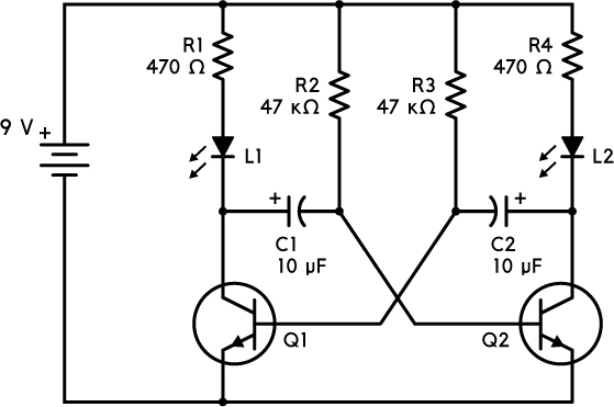
Having a good handle on the basics of electronics, especially on how voltages behave in circuits with capacitors, will help you understand what’s happening here. In this circuit, shown in Figure 6-1, the LED on the left-hand side is lit when the transistor on the left-hand side (Q1) is on, and the LED on the right-hand side is lit when the transistor on the right-hand side (Q2) is on. Transistor Q1 is controlled by the voltage at the junction between R3 and C2, while transistor Q2 is controlled by the voltage at the junction between R2 and C1.
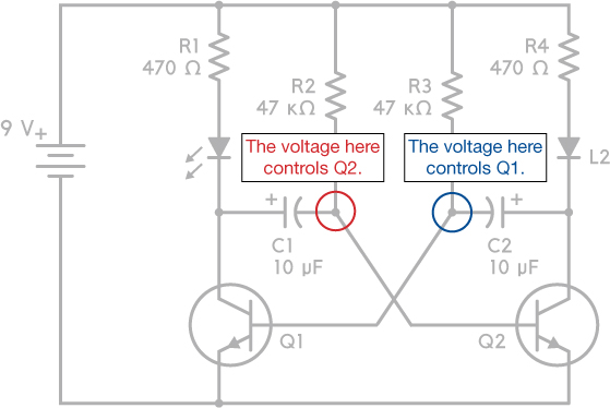
FIGURE 6-1 The voltage on the left node controls the right transistor (Q2) and vice versa.
Next, you have to look in detail at the voltages across the two capacitors. If you aren’t comfortable with how voltages and currents behave in a circuit, I recommend reading this article before you move on: https://www.build-electronic-circuits.com/kirchhoffs-law/.
Here are two things to keep in mind before diving into the explanation:
- Voltage is always measured between two points. When we talk about the voltage at a specific point, we mean the voltage measured from that point to the battery’s negative terminal—that’s why the negative terminal is 0 V.
- Throughout this book, we’re using the transistor as a switch. It needs 0.7 V on the middle pin (base) to turn on. When the transistor is on, its top pin (collector) is connected to its bottom pin (emitter) so that current can flow through it. This also means that the top pin has the same voltage as the bottom pin when the transistor is on. When the transistor is off, there’s no connection between the top pin and the bottom pin, so no current can flow.
Let’s start by looking at the circuit when LED L1 is lit and the other LED is off. L1 is lit only when transistor Q1 is turned on. Remember that Q1 is turned on only if it has 0.7 V on its base. Since the negative (–) side of capacitor C2 is connected to the base of Q1, this must also be 0.7 V.
The positive side of C2 is connected to the 9 V through R4 and L2, and it almost instantly charges to about 8 V (some voltage is used up across LED L2). You may be thinking, “Hey, if there is current flowing through R4 and L2, why isn’t L2 lit?” The reason is that as soon as the voltage on the right side of the capacitor rises to 8 V, no more current flows through the LED, and thus it doesn’t light up.
Figure 6-2 shows the voltages we have found so far.
FIGURE 6-2 The voltage on the positive side of capacitor C2 quickly reaches about 8 V when the LED on the left is lit.
Now let’s look at the voltages for the other transistor, Q2.
Since the transistor is off, its base must be lower than 0.7 V. The negative side of C1 is connected to the base, so that means it is also lower than 0.7 V. But the negative side of C1 is also connected to 9 V through resistor R2, which means it is being charged and the voltage is slowly increasing from below 0.7 V, as shown in Figure 6-3.

FIGURE 6-3 The voltage on the right of C1 is somewhere below 0.7 V, but increasing, when the left LED is lit.
So the voltage on the negative side of C1 is rising, and when it reaches 0.7 V, the action starts. When the negative side of C1 reaches 0.7 V, transistor Q2 gets 0.7 V on its base and turns on; this means the LED on the right also turns on.
When Q2 turns on, something interesting happens with the voltages on capacitor C2: from Figure 6-2, we know that C2 had 0.7 V on its negative side and 8 V on its positive side. Or, put another way, the negative side was 7.3 V lower than the positive side. But now that Q2 turns on, the voltage on the positive side of C2 is suddenly pulled down to 0 V through the transistor. The internal charge of the capacitor doesn’t change instantly, though, so the voltage difference across C2 initially stays the same, with the negative side 7.3 V lower than the positive side. But now that the positive side is 0 V, the negative side becomes 7.3 V below 0, or –7.3 V! With –7.3 V on the negative side of C2, the base of transistor Q1 also gets –7.3 V, which turns it off (see Figure 6-4).
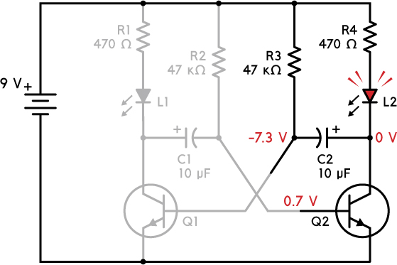
FIGURE 6-4 When transistor Q2 turns on, the transistor and LED on the left turn off.
So now, the left LED and transistor have turned off. And the right LED and transistor have turned on, as shown in Figure 6-4. The negative side of C2 starts at –7.3 V and is being charged through resistor R3—and is therefore rising. Since this is connected to the base of transistor Q1, when it reaches 0.7 V, Q1 turns on again, and the cycle repeats. The two transistors keep alternating between on and off, which makes the two LEDs alternate between on and off as well.